EP0876978B1 - Dispositif pour gondoler du matériau en couche, spécialment du papier - Google Patents
Dispositif pour gondoler du matériau en couche, spécialment du papier Download PDFInfo
- Publication number
- EP0876978B1 EP0876978B1 EP98105172A EP98105172A EP0876978B1 EP 0876978 B1 EP0876978 B1 EP 0876978B1 EP 98105172 A EP98105172 A EP 98105172A EP 98105172 A EP98105172 A EP 98105172A EP 0876978 B1 EP0876978 B1 EP 0876978B1
- Authority
- EP
- European Patent Office
- Prior art keywords
- learning
- surface areas
- surface area
- deflection
- guiding surface
- Prior art date
- Legal status (The legal status is an assumption and is not a legal conclusion. Google has not performed a legal analysis and makes no representation as to the accuracy of the status listed.)
- Revoked
Links
- 239000000463 material Substances 0.000 title claims description 71
- 238000011144 upstream manufacturing Methods 0.000 claims description 4
- 239000002245 particle Substances 0.000 claims description 2
- 230000000284 resting effect Effects 0.000 claims 1
- 239000010410 layer Substances 0.000 description 5
- 238000009499 grossing Methods 0.000 description 4
- 238000003860 storage Methods 0.000 description 4
- 230000005540 biological transmission Effects 0.000 description 3
- 230000001154 acute effect Effects 0.000 description 2
- 238000005452 bending Methods 0.000 description 2
- 239000012530 fluid Substances 0.000 description 2
- 238000003754 machining Methods 0.000 description 2
- 239000002390 adhesive tape Substances 0.000 description 1
- 239000000969 carrier Substances 0.000 description 1
- 239000000919 ceramic Substances 0.000 description 1
- 238000011109 contamination Methods 0.000 description 1
- 230000001066 destructive effect Effects 0.000 description 1
- 239000000428 dust Substances 0.000 description 1
- 230000000694 effects Effects 0.000 description 1
- 239000013013 elastic material Substances 0.000 description 1
- 230000001771 impaired effect Effects 0.000 description 1
- 230000001939 inductive effect Effects 0.000 description 1
- 230000005764 inhibitory process Effects 0.000 description 1
- 238000012423 maintenance Methods 0.000 description 1
- 238000004519 manufacturing process Methods 0.000 description 1
- 239000002184 metal Substances 0.000 description 1
- 230000003287 optical effect Effects 0.000 description 1
- 230000000149 penetrating effect Effects 0.000 description 1
- 230000002441 reversible effect Effects 0.000 description 1
- 238000005096 rolling process Methods 0.000 description 1
- 239000002356 single layer Substances 0.000 description 1
- 239000000758 substrate Substances 0.000 description 1
- 239000000725 suspension Substances 0.000 description 1
Images


Classifications
-
- B—PERFORMING OPERATIONS; TRANSPORTING
- B65—CONVEYING; PACKING; STORING; HANDLING THIN OR FILAMENTARY MATERIAL
- B65H—HANDLING THIN OR FILAMENTARY MATERIAL, e.g. SHEETS, WEBS, CABLES
- B65H23/00—Registering, tensioning, smoothing or guiding webs
- B65H23/04—Registering, tensioning, smoothing or guiding webs longitudinally
- B65H23/34—Apparatus for taking-out curl from webs
-
- B—PERFORMING OPERATIONS; TRANSPORTING
- B65—CONVEYING; PACKING; STORING; HANDLING THIN OR FILAMENTARY MATERIAL
- B65H—HANDLING THIN OR FILAMENTARY MATERIAL, e.g. SHEETS, WEBS, CABLES
- B65H2601/00—Problem to be solved or advantage achieved
- B65H2601/50—Diminishing, minimizing or reducing
- B65H2601/52—Diminishing, minimizing or reducing entities relating to handling machine
Definitions
- the invention relates to a device with which flexible bending or elastic materials e.g. to achieve a desired stress-free shape, such as a plan shape can be.
- Such materials can be constant thick substrates or other rollable materials that are in individual cuts or processed as an endless material web become.
- paper has in that it is wound into a roll
- a tendency to curl i.e. a flat part of the material web is under inherent bending stress and therefore the material part upon release of external forces for curvature or Rolling up tends to relieve tension.
- it can also be necessary to lay a stress-free flat To adjust or edit part of the material so that it is a Occupies the curvature position.
- the Material in the area of contact with the leveling surface Wrap angle determines which by location a deflection or guide adjacent to the leveling surface is intended for the material.
- This redirection can upstream and / or downstream of the straightening surface be provided.
- the deflection arrangement and the alignment surface arrangement expediently adjustable against each other are expediently adjustable against each other.
- the alignment surface can be stored on the device frame be that during the entire straightening job can be adjusted relative to the deflection, e.g. around consecutive pieces of material with itself changing curl in the same, tension-free To convert plan form or the like.
- a space-consuming Training with complicated controls and sluggish tax movements reveal what the quick response to different Curl or other properties of the Materials difficult.
- DE 195 06 465 A1 describes a smoothing device for a paper web has become known, which on one by one Center axis adjustable disc and a deflecting rod has a deflection roller. By turning the disc around the deflection rod and roller can be adjusted to its center be that the paper web either straight without Influenced through or first by the deflecting rod and then deflected by the pulley. Between The paper web is inserted into the deflecting rod and roller Way back that is the multiple of the roller radius or Rod radius is.
- WO 94/21546 A describes a device for smoothing of flat material in which the flat material between two spaced apart Rolls or rods runs through. Their distance from each other is unchangeable and the paper web contacted only one of the roles respectively Rods. This allows the direction of smoothing to be changed.
- EP 0 374 827 A relates to a smoothing device, where the flat material is led around the edge of a bar whose employment is at a distance of her arranged idler adjustable or by suspension is changeable.
- the invention has for its object a straightening device to create at what disadvantages known Training or the type described are avoided and especially with simple training and low-vibration barrel different Allows voltage to be introduced into the material.
- the e.g. through the deflection surface and the guiding surfaces formed as gap boundaries a relatively narrow passage gap for the material that the material is preferably free of compressive stress passes or in its gap width or the like is so variable that it when wrapping the leveling surface through the material several times smaller than the mentioned turning radius has the smallest gap width.
- This gap width is e.g. in one through the center of the straightening surface or the wrap angle measuring the axial plane of the deflection.
- the smallest gap width can also be smaller than half Quarter or a tenth of the turning radius or less than 50 or 30 times the thickness of the material so that the free running distance between the two guiding surfaces at most as large as the deflection radius or accordingly one of the specified values is smaller.
- the leveling surface can also be used here during work be adjusted, but it is particularly useful if only the deflection is adjusted transversely to the deflection axis is because this results in relatively small maximum travel ranges as well as positioning times.
- the deflection surface can be tangential to the level of one adjoining the straightening surface Flank surface and the tangential point of one Position outside of the flank surface and opposite the leveling surface stepless to the area of the flank surface and be changed behind the leveling surface. This follows especially if the associated actuating axis is outside the Deflection axes of the upstream or downstream to the straightening surface next deflection surface and therefore by the Adjustment movement the gap width of the passage gap slightly is changed.
- a paper web to be processed subsequently becomes useful with its front end overlapping at the rear end of one leading paper web, e.g. with an adhesive tape, attached before these ends or the seam the processing station to reach. If the seam with curvature or Wrap angle through the machining intervention on the Aligned surface or the like. So it can tear easily.
- the Guiding surfaces are therefore for the passage of the interface in a very short impulse movement against each other adjustable so that the interface on one or both guide surfaces passed without curvature or even touch can be excluded and therefore this type of damage is.
- the device for directional intervention only on one Surface side of the layer material can be formed, it is useful for alternating directional intervention in both Flat sides trained.
- the deflection surfaces provided for this on the one hand and the straightening surfaces on the other are mutually turned towards and can be at a minimum distance from each other which are at most as large as the deflection radius or is smaller.
- the deflection surfaces can be rotated or rollers are formed, the clear spacing, measured in their common axial plane, smaller than you Radius is.
- the material can be guided simultaneously and therefore alternately be curved in opposite directions.
- suction is provided, with which especially in the area of the guide surfaces or the passage gap Particles from dust, paper or the like continuously can be suctioned off.
- the suction mouth has an axial view a shape deviating from the circular shape, so that in the associated gap limitation only a single suction opening is required.
- the straightening body is easy to replace, if necessary jointly with a support body, opposite the device frame radially expandable, i.e. transverse to the longitudinal direction of the straightening surface or the width direction of the material.
- the expansion or that Replacement can therefore also take place if the material enforces the device as intended. same for also for the deflection arrangement or the individual deflection body.
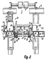
- FIG. 1 Several straightening devices 1 are horizontal according to FIG. 1 immediately one behind the other with the space requirement for a straightening device 1 smaller intermediate distances in one Straightening station 2 arranged to each a separate layer material 3 to work in a work area.
- these Working areas of the same devices 1 have the Materials 3 parallel, inclined downward running directions 4 in parallel running planes 5.
- Each of the Devices 1 is easily detachable as a single module a frame 6 arranged.
- a multi-layer material web 7 from the initially congruent materials 3 becomes horizontal and above the devices 1 the station 2 of separate role stores directly fed, first aligned with a deflection 9 and then downstream of it the individual materials 3 one after the other at an upper deflection 8 the web 7 deflected and the associated device 1 fed straight stretched. From the work area each material 3 stretched down below Deflections 11 supplied at which the materials 3 be laid one after the other to the track 7.
- the frame 6 Before and after the devices 1, the frame 6 has in each case a portal 12 or 13 composed of rods, their vertical supports over two sides of the material 3 horizontal horizontal beams 14 connected together are.
- the longitudinal members 14 carry the on their tops Device modules 1 and together with these as Unit can be removed from the rest of the frame 12, 13.
- the upper ends of the portals 12, 13 are also via side members connected, at which the deflections 8 one behind the other are rotatably mounted as rollers.
- the working area of the individual devices 1 will single-layer material 3 as an endless web over a cylindrical Guiding or deflecting surface 15 supplied, which the material 3rd over an angle of at most 90 °. Of the The surface 15 reaches the stretched material directly Guide or straightening surface 16, which by a cross-section rounded corner edge is formed.
- the guide surface 15 is by a rotating roller or deflector 17 and the Straightening surface 16 formed by a stationary straightening body 18, which consistently rectangular flat cross sections has and how the deflector 17 continuously over the Material width runs through.
- In the work area or near the Passage gap 20 accruing contamination Flow, for example with a suction 19 during the Working operations are pneumatically removed.
- the towards 4 slit plane 10 inclined downwards of the slit 20 coincides with that flank of the leveling surface 16, which is directly opposite the guide surface 15 and through a continuously flat large surface 21 of the body 18 is formed.
- the running level 5 is stronger inclined so that the material 3 the gap 20 from a gap limitation 15 to the opposite gap limitation 16 passes through at an acute angle and then on the straightening surface 16 over an angle of less than 90 ° away from the guide surface 15 is deflected downwards.
- the free running distance of the Material 3 between the two gap boundaries 15, 16 is extremely short, but variable by setting. The free The running distance is smaller than the largest cross-sectional extent of the body 17 or 18 or as half or one Quarter of it.
- the guide surface 15 is around a horizontal plane 5 parallel deflection axis 22 perpendicular to direction 4 curved, while the straightening surface 16 is parallel to it alignable directional axis 24 is curved.
- the two convex curved surfaces 15, 16 have very different Radii of curvature, the radius of curvature of the surface 15 at least 10 to 20 times or 30 times larger than that Radius of curvature of the straightening surface 16.
- the guide surface 15 is about a positioning axis 25 that is fixed to the frame and parallel to axis 22 adjustable, which on the of the gap 20 or level 10 opposite side of the axis 22 or the body 17 is.
- the two ends of the body 17 are on two support cheeks 26, 27 attached or rotatably mounted, each with a bearings 28 and 29 on the associated outside the axis 25 rotatably supported over at least 120 ° or 360 ° are.
- the unit 17, 26, 27 can thereby, possibly together with the bearings 28, 29, radially away from the frame 6 become.
- continuous adjustment around axis 25 adjusting means 30 are provided, which have a standing Rotary motor 31 and one directly flanged to it Gearbox, such as an angular gear 32, which on the Top of a bracket 14 attached and self-locking is.
- the associated cheek 26 is immediately free on the protruding output shaft journal of the gear 32 attached, so that its warehouse directly the associated only bearing 28 for the actuator 17, 26, 27 forms and no other, separate or fixed on this side Stock is required.
- the actuating means 30, 40, 42, 43 or the suction 19 can either on both sides of the Gap 20 can be arranged, e.g. the transmission 32 optionally on one of the supports 14 and the connection 52, 53, 54, 55 to be arranged optionally in the area of one of the carriers 14 is.
- the operating side of the device 1 can be selected lie on each of these pages and, if necessary, by means 19, 30, 42 are kept free.
- the constant external cross-sections over its length having flat or rod body 18 is in an Cross section larger rod or support body 37 interchangeable attached, which is flat rectangular in cross section Is tubular body and the straightening body 18 on one its two wider outer surfaces.
- the edge surfaces of the straightening body adjoining the edges 16 18 are thus in the levels of the two narrower or outer surfaces of the body 37 lying at right angles thereto.
- the ends of the unit 18, 37, in particular only the ends of the Body 37 are rigid with circular disk-shaped flanges 38 ' connected, which on plate-shaped support flanges 38 of the Frame 2 interchangeable with screwed in outwards Axial screws are attached. After loosening the axial screws can the unit 18, 37 radially from the support flanges 38 ' removed or vice versa.
- the leveling surface 16 is opposite with adjusting means 39 or 40 the unit 17, 26, 27 and the frame 2 by two at right angles mutually lying adjusting axes 45, 46 separately and manually adjustable, namely with the adjusting means 40 during of the operation and with the adjusting means 39 during the Standstill of the device 1.
- the leveling surface 16 and axis 46 parallel to axes 22, 25 lies on that of Gap 20, 10 facing away from the straightening surface 16 approximately in the Center axis of the support body 37 or the associated flanges 38.
- These flanges 38 point for the passage of the above Axial screws around the axis 46 elongated holes, see above that the inclination of the straightening surface and gap flank 21st continuously changed and then by clamping with the axial screws can be secured.
- the edge 21 lies in one Position of the unit 15, 26, 27 perpendicular to the common Axial plane 47 of the axes 22, 25, this axial plane being the Flank 21 intersects immediately adjacent to the straightening surface 16. From this position, the levels 10, 47 after both opposite directions are continuously adjustable, namely also so that the axial plane 47 of the straightening surface 16 with Distance opposite and therefore at an angle to level 10.
- In the middle position is the width of the gap 20 at smallest and it takes on adjustment in both directions continuously as shown by the dot-dash line in FIG. 3 indicated positions can be seen.
- the smallest gap width is expediently more than one Millimeters and less than three or five millimeters. adjusting movements both adjusting means 30, 39 lead to such Changes, but only the adjusting means 39 the Specify the smallest possible gap width.
- the adjusting means 40 enable a mutual inclination the straightening surface 16 and the axes 24, 46 on the one hand and the guide surface 15 and the axes 22, 25 on the other hand, the said means over the travel of the actuating means 40 Gap widths remain constant. Adjust the adjusting means 40 one end of the unit remote from the actuating means 30 18, 37 about the actuating axis 25, while the other end of this Unit only pivots about the frame-fixed axis 45 and each including the associated support flange 38 '.
- the axis 45 is always in the same axial plane Axis 25 and laterally adjacent to those parallel to it Axial planes of the axes 22, 24, 46, the axis 22 with the Adjustment means 30 also transferred into this common axial plane can be.
- the support flange 38 'for one flange 38 adjustable with a guide 41 curved around the axis 25, which is a radial slot free in a curved slot engaging, rigidly connected to this support flange 38 ' Guide pin includes.
- the storage around the flank 21 or to the plane 10 transverse or inclined axis 45 is through a hinge 42 or a bearing formed, which one frame-fixed, located in the axis 45 hinge pin.
- Each of the bearings 41, 42 has a frame-fixed, laterally on the inside of the associated side member 14 attached bearing body 48, one of which is the Guide 41 and the other, fork-shaped, the hinge pin carries, which the associated support flange 38 'between the Fork arms of the associated bearing body 48 passes through.
- the unit 18, 37 only in the area of Guide 41 with suitable means 43, for example Clamp to be locked.
- suitable means 43 for example Clamp to be locked.
- Hand lever manually operated clamping device provided with which the guide 41 relative to the associated bearing body 48 can be clamped axially.
- To facilitate manual Adjustment along the guide 41 is the corresponding one Support flange 38 'adjacent to the inside of this bearing body 48 provided with a radially projecting handle 44.
- the Finding 43 is immediately at the bottom of the associated Side member 14 accessible.
- the straightening body 18 consists of a one-piece metal body, the whole or at least surface-treated in the area of the four longitudinal edges 16, e.g. with a vapor-deposited hard, like ceramic oxide layer or the like of, for example, at most one or half Tenths of a millimeter.
- the body 18 is optional about its central longitudinal axis and at right angles to it horizontal axis reversible so that each of its four edges 16th optionally in the same working position for engaging in the material 3 and brought against the carrier 37 can.
- the attachment 49 for the turning tool 18 includes 18 countersunk holes on both flat sides of the turning insert for fastening screws with which the tool 18 optionally with both flat sides against the associated flat side of the carrier 37 can be tensioned.
- the edges 16 can have different radii of curvature, so that the same tool 18 to adapt to different Processing requirements different working edges 16 having.
- the stationary and no changes in location during work exposed suction 19 includes a tool 18 in the Center between the edges 16 transversely penetrating, slit-shaped Fluid or suction opening 50, which is parallel to the Edges 16 and aligned between the counterbores 49.
- the associated wall of the carrier 37 is congruent Provide fluid opening which the in the flank 21st lying mouth of the opening 50 with a flow channel 51 combines.
- the only from the inside of the profile 37 limited and through its length channel 51 is on one or both ends with narrowed connections 52, which for two columns 20 on the opposite Outside of the support flanges 38 'laterally adjacent to Guide 41 or axis 45 are provided.
- At the connecting piece 52 is an associated carrier 14 on the Flexibly flexible line 53 crossing the underside, e.g.
- each carrier 14 there is one such Longitudinal channel 54 which is rectangular or square in cross section attached, in the side wall of the nozzle 55 under a acute angle obliquely to the direction of flow in channel 54 flows to avoid flow losses.
- a suitable Pressure or suction source such as a blower
- the Cheeks 26, 27 also have two separate deflecting surfaces 15, 15 'or the same deflection body 17 with separate deflection axes 22, 23, which are symmetrical on both sides of an axial plane the actuating axis 25 are arranged. In one position this axial plane coincides with the plane 45, so that the Material 3 from the deflection 8 to the deflection 11 without contact pass between the rollers 17 and the tools 18 can, so it is not distracted in the work area.
- Swiveling of the unit 17, 26, 27 in one direction in 3 is the material 3 of one Guide surface 15 by deflection on a material side with the opposite material side in directing engagement with one straightening surface, namely the right straightening surface 16 brought.
- By swiveling in the opposite direction is the material 3 in a corresponding manner by the other Deflection surface 15 ′ engages with the other straightening edge 16 brought.
- the wrap angle on the respective straightening edge 16 during operation can be changed dynamically and continuously, whereby also the wrap angle on the associated deflection surface 15, 15 'and the gap width of the gap 20 changes.
- the gear 32 locks through each setting by itself internal inhibition of its transmission links. Regardless, can this wrap angle and the gap width with the Adjusting means 39 can be changed, it is also conceivable the two flanges 38 with torsional deformation of the unit 18, 37 against each other to adjust the length of the Edge to achieve 16 different wrap angles, as is possible with the adjusting means 40.
- the dynamic adjustment not here with the tools 18, but is made with the deflections 17 results a very simple design of the suction 19.
- Each channel 51 is connected to one of the connections 52. All individual devices 1 are connected to the same longitudinal collecting duct 54. The named ends of the two channels 54 are over the mentioned, designed as a piece of pants, to the common riser 56 connected. Because the redirections 17 even in the case of a full rotation about the axis 25 Contact with the tools 18 or other components of the Device 1 can come, are also no means for Limitation of travel, such as limit switches, required. Any tool 18 or its tool edge 16 can also by a rotating Rod to be replaced, its bearing on the support flanges 38 'to be flanged or provided on the flanges 38. All components are exposed and are for maintenance or Introduce the material 3 very easily accessible.
- the material guide 57 points for each deflection surface 15, 15 'has an associated fixed frame Deflection 58, 58 'in the form of a cylinder rod or the like.
- the deflection surface 15 forms with the deflection 58 a narrow passage gap to the S-shaped changing Deflection of the material 3 and in the other position this deflection takes place in the region with an opposite curvature an identical deflection gap between the deflection surface 15 ' and the deflection 58 '.
- the material passes through the deflection gap each without clamping pressure, so that it is simultaneously is in contact with the deflector only on one side of the surface.
- the Deflections 58, 58 ' are fastened with flanges 59 and therefore adjustable as described using the flanges 38 as well removably attached to a support flange 59 '. So you can here also adjusting means according to means 39, 40 are provided be, the deflections 58, 58 'as the deflections 16 are each eccentric to the associated actuating axis.
- the deflections are 17th provided downstream of the straightening surfaces 16 and the Deflection 8 lies in a deflection corresponding to FIG. 1 Distance upstream from the straightening surface 16.
- a drive cylinder is provided as drive 31, which two separately controllable and in series rigid with each other connected single cylinder, the piston rods are directed away from each other. This allows any cylinder for themselves in both end positions, so that four stroke-limited strokes, namely each one Cylinder and the two working cylinders result.
Landscapes
- Registering, Tensioning, Guiding Webs, And Rollers Therefor (AREA)
- Treatment Of Fiber Materials (AREA)
- Bending Of Plates, Rods, And Pipes (AREA)
- Paper (AREA)
- Wire Processing (AREA)
Claims (13)
- Dispositif pour gondoler du matériau en couche, notamment du papier, avec un châssis de base (6) essentiellement stationnaire et avec une bande continue définissant un sens de marche (4) ainsi qu'en section transversale un plan de marche (5), des surfaces de guidage premières et deuxièmes (15, 16) étant prévues pour le matériau en couche (3), dont la première est prévue en tant que surface de dressage (16) et la deuxième en tant que surface directrice (15), les surfaces de guidage (15, 16) étant directement raccordées entre elles en état de travail normal par le matériau en couche qui passe de manière continue, caractérisé en ce que les surfaces de guidage (15, 16) sont ajustables l'une par rapport à l'autre avec une ampleur de fente variable pour la formation d'une fente de passage (20) modifiable pour le matériau en couche (3).
- Dispositif d'après la revendication 1, caractérisé en ce que les surfaces de guidage (15, 16) forment entre elles une fente de passage (20), dont l'ampleur de fente est inférieure à la moitié du rayon de renvoi de la surface directrice (15) et/ou à 50 fois l'épaisseur du matériau en couche (3).
- Dispositif d'après la revendication 2 caractérisé en ce que l'ampleur de fente de la fente de passage (20) est inférieure à un quart, notamment à un dixième du rayon de renvoi et/ou à 30 fois l'épaisseur du matériau en couche (3).
- Dispositif d'après une des revendications précédentes, caractérisé en ce que la surface directrice (15) est ajustable par rapport au châssis de base (6) et par rapport à la surface de dressage (16), en ce que notamment les surfaces de guidage (15, 16) sont ajustables l'une par rapport à l'autre autour d'un axe de réglage (25) à peu près parallèle par rapport au plan de marche (5) et en ce que de préférence les deux surfaces de guidage (15, 16) peuvent être pivotées autour de certains axes de réglage (25, 46) individuels, lesquels sont situés à des côtés opposés d'un plan de fente (10) de la fente de passage (20).
- Dispositif d'après une des revendications précédentes, caractérisé en ce que les surfaces de guidage (15, 16) sont ajustables l'une par rapport à l'autre par un moyen de réglage (30) pour la modification de l'angle d'enroulement auprès au moins d'une des surfaces de guidage (15, 16), et en ce que de préférence les surfaces de guidage (15, 16) peuvent être réglées pour le passage essentiellement rectiligne ainsi que prive de contact direct du matériau en couche (3).
- Dispositif d'après une des revendications précédentes, caractérisé en ce qu'au moins une des surfaces de guidage (15, 15', 16) est prévue pour être jointe à des faces de couche opposées l'une à l'autre du matériau en couche (3), en ce que notamment au moins une des surfaces de guidage est formée par des surfaces individuelles (15, 15' ou encore 16) séparées et situées des deux côtés de la voie de déroulement, et en ce que de préférence deux surfaces directrices individuelles (15, 15') écartées l'une de l'autre sont ajustables ensemble par rapport à la surface de dressage (16).
- Dispositif d'après une des revendications précédentes, caractérisé en ce qu'à proximité de la fente de passage (20) un moyen est prévu pour l'écartement de particules, tel qu'un moyen d'aspiration (19), en ce que notamment le moyen (19) comprend une ouverture de logement (50) pour les particules en forme de fente et limitrophe à la fente de passage (20), et en ce que de préférence une ouverture d'aspiration (50) est logée de manière ajustable avec la surface de dressage (16) ainsi qu'indépendamment de la surface directrice (15, 15').
- Dispositif d'après une des revendications précédentes, caractérisé en ce qu'un corps de dressage (18) formant la surface de dressage (16) est fixé sur une tige de support (37) de manière détachable essentiellement sur sa longueur, en ce que notamment la tige de support (37) est un profil creux plat et rectangulaire, et en ce que de préférence la tige de support (37) présente à l'intérieur un conduit de transport (51), lequel traverse une paroi de la tige de support (37) ainsi que le corps de dressage (18) adjacent à cette paroi.
- Dispositif d'après une des revendications précédentes, caractérisé en ce que la surface de dressage (16) est formée par une arête flanquée par des surfaces angulaires, en ce que notamment quatre surfaces de dressage (16) individuelles flanquées par quatre surfaces angulaires constituent, en étant raccordées entre elles de manière fixe, une unité de montage et peuvent être mises au choix dans un état de service à partir d'un état de repos par retournement, et en ce que de préférence le moyen de renvoi (15, 15') est ajustable dans une position tangentielle par rapport à une des surfaces angulaires (21).
- Dispositif d'après une des revendications précédentes, caractérisé en ce qu'un corps de dressage (18) formant la surface de dressage (16) peut être radialement ôté du dispositif (1) sans enlever d'autres surfaces de guidage (15, 15', 16), en ce que notamment la tige de support (37) peut être radialement démontée ensemble avec le corps de dressage (18), et en ce que de préférence dans le domaine des extrémités du corps de dressage (18) sont prévues des brides de palier (38), lesquelles sont fixées à des contre-brides (38', 48) du châssis de base (6) de manière ajustable autour d'un axe de réglage (46) ainsi que de manière facilement amovible.
- Dispositif d'après une des revendications précédentes, caractérisé en ce que la surface de dressage (16) est inclinable par rapport à la surface directrice (15, 15'), en ce que notamment une première extrémité de la surface de dressage (16) est pivotable essentiellement autour de l'axe de réglage (25) de la surface directrice (15, 15'), et en ce que de préférence deux extrémités de deux surfaces de dressage individuelles (16) opposées l'une par rapport à l'autre sont ajustables ensemble autour d'un axe directeur (45) situé en substance transversalement de manière orthogonale par rapport à la direction longitudinale de celles-ci.
- Dispositif d'après une des revendications précédentes, caractérisé en ce qu'au moins une des surfaces de guidage (15, 16) est ajustable par moteur par un moyen de réglage (30) pendant le service normal, en ce que notamment le moyen de réglage (30) comprend un moteur rotationnel (31) disposé transversalement par rapport au plan de marche (5), et en ce que de préférence le moyen de réglage (30) comprend un engrenage (32), tel qu'un engrenage angulaire bridé directement au moteur rotationnel (31), avec un arbre mené d'engrenage, lequel est situé dans l'axe de réglage (25) de la surface directrice (15, 15') et axialement de manière directement limitrophe à la surface directrice.
- Dispositif d'après une des revendications précédentes, caractérisé en ce qu'un certain nombre de bandes continues individuelles avec des dispositifs de dressage individuels (1) séparés pour des matériaux en couche (3) individuels sont disposés l'un à côté de l'autre dans une station de dressage (2), en ce que notamment en amont de la station de dressage (2) des moyens de renvoi d'admission (8) individuels situés l'un derrière l'autre en sens de marche sont prévus pour la dérivation consécutive du matériau en couche (3) respectif à partir d'une bande de matériau (7) en plusieurs couches, et en ce que de préférence en aval de la station de dressage (2) des moyens de renvoi groupés (11) situés l'un derrière l'autre en sens de marche sont prévus pour la conjonction en plusieurs couches des matériaux en couche (3) usinés dans les fentes de passage (20).
Applications Claiming Priority (2)
| Application Number | Priority Date | Filing Date | Title |
|---|---|---|---|
| DE19713207A DE19713207A1 (de) | 1997-03-28 | 1997-03-28 | Richtvorrichtung für Lagenmaterial, insbesondere Papier |
| DE19713207 | 1997-03-28 |
Publications (3)
| Publication Number | Publication Date |
|---|---|
| EP0876978A2 EP0876978A2 (fr) | 1998-11-11 |
| EP0876978A3 EP0876978A3 (fr) | 1999-08-18 |
| EP0876978B1 true EP0876978B1 (fr) | 2003-11-12 |
Family
ID=7824991
Family Applications (1)
| Application Number | Title | Priority Date | Filing Date |
|---|---|---|---|
| EP98105172A Revoked EP0876978B1 (fr) | 1997-03-28 | 1998-03-21 | Dispositif pour gondoler du matériau en couche, spécialment du papier |
Country Status (6)
| Country | Link |
|---|---|
| US (1) | US6302678B1 (fr) |
| EP (1) | EP0876978B1 (fr) |
| JP (1) | JPH10273258A (fr) |
| KR (1) | KR19980080811A (fr) |
| DE (2) | DE19713207A1 (fr) |
| ES (1) | ES2210609T3 (fr) |
Families Citing this family (3)
| Publication number | Priority date | Publication date | Assignee | Title |
|---|---|---|---|---|
| US20040152033A1 (en) * | 2003-02-03 | 2004-08-05 | Collins John A. | Orthodontic appliance |
| KR101023231B1 (ko) * | 2008-11-25 | 2011-03-21 | 한국전기연구원 | 틸트형 멀티 턴 릴투릴 이송장치 |
| US9290283B2 (en) | 2012-03-16 | 2016-03-22 | Pemco Inc. | Method and apparatus for wrapping a folio ream of paper |
Family Cites Families (19)
| Publication number | Priority date | Publication date | Assignee | Title |
|---|---|---|---|---|
| DE483673C (de) * | 1929-10-03 | Otto Philipp Fa | Vorrichtung zum Geraderichten von gerollten Papierbahnen oder -boegen | |
| US2070505A (en) * | 1929-10-24 | 1937-02-09 | Charles J Beck | Decurling device |
| US3649447A (en) * | 1969-09-09 | 1972-03-14 | Xerox Corp | Apparatus for decurling a paper web |
| US3661703A (en) * | 1970-03-30 | 1972-05-09 | Westvaco Corp | Decurling apparatus |
| US3772145A (en) * | 1971-03-31 | 1973-11-13 | Black Clawson Co | Pivotal mounting structures for vertical twin-wire papermaking machine |
| US4013284A (en) * | 1975-10-14 | 1977-03-22 | Eastern Graphic Products, Inc. | Decurler device |
| US4111745A (en) * | 1977-08-08 | 1978-09-05 | The Moore & White Company | Adjustable bearing assembly for web decurling apparatus |
| CH623285A5 (en) * | 1978-06-21 | 1981-05-29 | Bobst Fils Sa J | Method for acting on the fibres of a material in the form of a moving web and device for implementing the method |
| US4539072A (en) * | 1984-01-31 | 1985-09-03 | Beloit Corporation | Curl neutralizer |
| DE3833804A1 (de) * | 1987-10-07 | 1989-06-08 | Steffen & Bergmann Konstruktio | Brecherleiste fuer papierverarbeitungsmaschinen |
| FR2641767A1 (fr) * | 1988-12-23 | 1990-07-20 | Alcatel Business Systems | Ensemble de planage de documents |
| DE69030965T2 (de) * | 1989-07-27 | 1998-01-29 | Canon Kk | Vorrichtung zum Ausgleichen der Wellungen |
| US5269743A (en) * | 1990-06-12 | 1993-12-14 | Jujo Paper Co., Ltd. | Method of imparting increased foldability to fold lines in paperboard material for paper containers |
| US5009749A (en) * | 1990-08-09 | 1991-04-23 | Martin Automatic, Inc. | Web decurler |
| US5154688A (en) * | 1991-09-06 | 1992-10-13 | Boyd Brent A | Decurling bar cover |
| FR2702993B1 (fr) * | 1993-03-24 | 1995-12-08 | Komori Chambon | Dispositif de redressement d'une nappe de matiere, par exemple de carton, defilant en continu . |
| US5539511A (en) * | 1994-12-16 | 1996-07-23 | Xerox Corporation | Multilevel/duplex image sheet decurling apparatus |
| DE19506465C2 (de) * | 1995-02-24 | 1997-01-16 | Boewe Systec Ag | Glättvorrichtung für eine Papierbahn in einer papierverarbeitenden Maschine |
| DE29600403U1 (de) * | 1996-01-11 | 1996-03-07 | Heidelberger Druckmaschinen Ag, 69115 Heidelberg | Vorrichtung zum Glätten von Bögen in Druckmaschinen |
-
1997
- 1997-03-28 DE DE19713207A patent/DE19713207A1/de not_active Withdrawn
-
1998
- 1998-03-20 JP JP10090595A patent/JPH10273258A/ja active Pending
- 1998-03-21 EP EP98105172A patent/EP0876978B1/fr not_active Revoked
- 1998-03-21 DE DE59810124T patent/DE59810124D1/de not_active Revoked
- 1998-03-21 ES ES98105172T patent/ES2210609T3/es not_active Expired - Lifetime
- 1998-03-27 US US09/049,731 patent/US6302678B1/en not_active Expired - Fee Related
- 1998-03-27 KR KR1019980010821A patent/KR19980080811A/ko not_active Withdrawn
Also Published As
| Publication number | Publication date |
|---|---|
| JPH10273258A (ja) | 1998-10-13 |
| DE59810124D1 (de) | 2003-12-18 |
| US6302678B1 (en) | 2001-10-16 |
| DE19713207A1 (de) | 1998-10-01 |
| EP0876978A3 (fr) | 1999-08-18 |
| ES2210609T3 (es) | 2004-07-01 |
| KR19980080811A (ko) | 1998-11-25 |
| EP0876978A2 (fr) | 1998-11-11 |
Similar Documents
| Publication | Publication Date | Title |
|---|---|---|
| DE69008256T2 (de) | Vorrichtung zum Rillen und Schneiden endloser Bahnen aus Pappe und dergleichen. | |
| DE2803386C2 (fr) | ||
| DE69022840T2 (de) | Fördertisch. | |
| DE69821414T2 (de) | Schneid- und Rillmaschine mit einer Vorrichtung zum Längsschneiden | |
| DE4314653C2 (de) | Mehrzweckkalander | |
| DE1602597B2 (de) | Einstellvorrichtung für den Walzenspalt einer Walzmaschine | |
| EP2415700A2 (fr) | Dispositif d'orientation d'un produit plat | |
| EP0808789A1 (fr) | Dispositif pour guider des bandes multicouches en papier ou analogue | |
| EP1012097B1 (fr) | Dispositif de guidage d'une bande de papier sans fin | |
| CH698689A2 (de) | Flexibelbogen für eine Wanderdeckelkarde sowie Wanderdeckelkarde. | |
| EP0876978B1 (fr) | Dispositif pour gondoler du matériau en couche, spécialment du papier | |
| DE1919470C3 (de) | Materialschneidmaschine | |
| EP0913248A2 (fr) | Dispositif de soudage pour souder des bords de feuilles par recouvrement | |
| DE102010005757B3 (de) | Vorrichtung und Verfahren zum Führen von miteinander entlang ihrer Längskanten zu fügender Bänder | |
| DE4413008A1 (de) | Faltvorrichtung für Blattlagen | |
| EP0677372A2 (fr) | Appareil d'étirage longitudinal, spécialement pour feuilles thermoplastiques | |
| EP1112952B1 (fr) | Dispositif pour plier en continu de matériau plat | |
| DE2149172B2 (de) | Vorrichtung zum Strecken und Glätten von Tabakblättern | |
| EP0824083B1 (fr) | Dispositif pour enlever des feuilles d'une pile et pour transporter les feuilles loin de la pile | |
| DE3744107C2 (fr) | ||
| DE8915626U1 (de) | Vorrichtung zum schwebenden Führen von zu fördernden Materialbahnen oder Materialbogen | |
| DE3310356C2 (fr) | ||
| DE19513688A1 (de) | Vorrichtung zur Bearbeitung von Lagen-Material | |
| EP0903308A1 (fr) | Roue à étoile pour transférer des objets d'un premier convoyeur à un deuxième | |
| DE3114615A1 (de) | Schleifvorrichtung zur erzeugung konvexer prifle an geradlinigen kanten |
Legal Events
| Date | Code | Title | Description |
|---|---|---|---|
| PUAI | Public reference made under article 153(3) epc to a published international application that has entered the european phase |
Free format text: ORIGINAL CODE: 0009012 |
|
| AK | Designated contracting states |
Kind code of ref document: A2 Designated state(s): DE ES GB IT |
|
| AX | Request for extension of the european patent |
Free format text: AL;LT;LV;MK;RO;SI |
|
| RTI1 | Title (correction) | ||
| RTI1 | Title (correction) |
Free format text: DEVICE TO CURL PLY-MATERIAL, ESPECIALLY PAPER |
|
| PUAL | Search report despatched |
Free format text: ORIGINAL CODE: 0009013 |
|
| AK | Designated contracting states |
Kind code of ref document: A3 Designated state(s): AT BE CH DE DK ES FI FR GB GR IE IT LI LU MC NL PT SE |
|
| AX | Request for extension of the european patent |
Free format text: AL;LT;LV;MK;RO;SI |
|
| 17P | Request for examination filed |
Effective date: 19990921 |
|
| AKX | Designation fees paid |
Free format text: DE ES GB IT |
|
| 17Q | First examination report despatched |
Effective date: 20010504 |
|
| GRAH | Despatch of communication of intention to grant a patent |
Free format text: ORIGINAL CODE: EPIDOS IGRA |
|
| GRAH | Despatch of communication of intention to grant a patent |
Free format text: ORIGINAL CODE: EPIDOS IGRA |
|
| GRAA | (expected) grant |
Free format text: ORIGINAL CODE: 0009210 |
|
| AK | Designated contracting states |
Kind code of ref document: B1 Designated state(s): DE ES GB IT |
|
| REG | Reference to a national code |
Ref country code: GB Ref legal event code: FG4D Free format text: NOT ENGLISH |
|
| GBT | Gb: translation of ep patent filed (gb section 77(6)(a)/1977) |
Effective date: 20031112 |
|
| REF | Corresponds to: |
Ref document number: 59810124 Country of ref document: DE Date of ref document: 20031218 Kind code of ref document: P |
|
| PGFP | Annual fee paid to national office [announced via postgrant information from national office to epo] |
Ref country code: GB Payment date: 20040406 Year of fee payment: 7 |
|
| PGFP | Annual fee paid to national office [announced via postgrant information from national office to epo] |
Ref country code: DE Payment date: 20040417 Year of fee payment: 7 |
|
| PGFP | Annual fee paid to national office [announced via postgrant information from national office to epo] |
Ref country code: ES Payment date: 20040427 Year of fee payment: 7 |
|
| REG | Reference to a national code |
Ref country code: ES Ref legal event code: FG2A Ref document number: 2210609 Country of ref document: ES Kind code of ref document: T3 |
|
| PLBQ | Unpublished change to opponent data |
Free format text: ORIGINAL CODE: EPIDOS OPPO |
|
| PLBI | Opposition filed |
Free format text: ORIGINAL CODE: 0009260 |
|
| PLAX | Notice of opposition and request to file observation + time limit sent |
Free format text: ORIGINAL CODE: EPIDOSNOBS2 |
|
| 26 | Opposition filed |
Opponent name: E.C.H. WILL GMBH Effective date: 20040806 |
|
| PLBB | Reply of patent proprietor to notice(s) of opposition received |
Free format text: ORIGINAL CODE: EPIDOSNOBS3 |
|
| RDAF | Communication despatched that patent is revoked |
Free format text: ORIGINAL CODE: EPIDOSNREV1 |
|
| RDAG | Patent revoked |
Free format text: ORIGINAL CODE: 0009271 |
|
| STAA | Information on the status of an ep patent application or granted ep patent |
Free format text: STATUS: PATENT REVOKED |
|
| 27W | Patent revoked |
Effective date: 20041204 |
|
| GBPR | Gb: patent revoked under art. 102 of the ep convention designating the uk as contracting state |
Free format text: 20041204 |