EP0877115A2 - Dispositif d'aspiration - Google Patents
Dispositif d'aspiration Download PDFInfo
- Publication number
- EP0877115A2 EP0877115A2 EP98107580A EP98107580A EP0877115A2 EP 0877115 A2 EP0877115 A2 EP 0877115A2 EP 98107580 A EP98107580 A EP 98107580A EP 98107580 A EP98107580 A EP 98107580A EP 0877115 A2 EP0877115 A2 EP 0877115A2
- Authority
- EP
- European Patent Office
- Prior art keywords
- screen cylinder
- suction
- cylinder
- suction device
- web
- Prior art date
- Legal status (The legal status is an assumption and is not a legal conclusion. Google has not performed a legal analysis and makes no representation as to the accuracy of the status listed.)
- Granted
Links
Images

Classifications
-
- D—TEXTILES; PAPER
- D06—TREATMENT OF TEXTILES OR THE LIKE; LAUNDERING; FLEXIBLE MATERIALS NOT OTHERWISE PROVIDED FOR
- D06B—TREATING TEXTILE MATERIALS USING LIQUIDS, GASES OR VAPOURS
- D06B15/00—Removing liquids, gases or vapours from textile materials in association with treatment of the materials by liquids, gases or vapours
- D06B15/04—Removing liquids, gases or vapours from textile materials in association with treatment of the materials by liquids, gases or vapours by suction
-
- F—MECHANICAL ENGINEERING; LIGHTING; HEATING; WEAPONS; BLASTING
- F26—DRYING
- F26B—DRYING SOLID MATERIALS OR OBJECTS BY REMOVING LIQUID THEREFROM
- F26B13/00—Machines and apparatus for drying fabrics, fibres, yarns, or other materials in long lengths, with progressive movement
- F26B13/24—Arrangements of devices using drying processes not involving heating
- F26B13/30—Arrangements of devices using drying processes not involving heating for applying suction
Definitions
- the invention relates to a suction device the preamble of claim 1 corresponding type.
- Such a suction device is from DE-OS 2 403 815, Fig. 2, known.
- the from the only schematic representation in DE-OS 2 403 815 emerging suction device is used to drain a carpet sheet by suction from the pole side.
- the sieve drum runs across the Suction chamber so that in the area of the suction chamber web and support drum moves at the same speed will.
- the support drum supports the web against the Force of the suction above the suction slot and prevents that the web is drawn into the suction slot.
- the screening drum causes the web to be largely be guided over the suction slot without force can, insofar as the web cannot touch the suction slot delimiting wall parts of the suction chamber and must be moved against the friction there.
- the web of goods is, as it were, from the screening drum carried the suction slot and does not have to over the Suction slit are dragged over.
- the screen cylinder a sieve drum with a fixed circular cross section.
- To the Sieve drum to the required structural strength lend are a certain flexural strength of the wire mesh and a certain minimum diameter of the wire required. It turns out that with a practicable Compromise between structural strength and support density of the wire mesh for such a screen drum 45% opening percentage can hardly be exceeded can. This in turn also makes the suction efficiency one limited such arrangement.
- the opening percentage is the one Surface area of the wire mesh that is not covered by the Wires is covered. The rest is the wire occupied floor plan.
- DE-OS 2 403 815 is an alternative embodiment shown, in which instead of the screen cylinder an endlessly running sieve belt across the suction slot is guided, which is guided over three pulleys is.
- an endlessly running sieve belt across the suction slot is guided, which is guided over three pulleys is.
- the processed Length of such a belt if sufficient Lateral guidance of the same should be possible, at least be one and a half times the width of the screen belt got to.
- Such a sieve belt if a clean one lateral guidance should be possible, a certain minimum wire size exhibit.
- the invention has for its object an improved To create suction device of the type in question.
- screen cylinder is here in the mathematical Meaning, i.e. it is a pipe or tubular fabric made of parallel lines Generating. However, the fabric has none unchangeable cross section, but is easily deformable.
- the dimensional stability of the screen cylinder according to the invention should be such that he is still just independent can stand upright, but by hand in its cross section is easily compressible.
- the screen cylinder should can deform a little while moving around, without however, as in the known screen belt suction device under longitudinal tension to be guided around pulleys.
- the formation of the "screen cylinder" as a flexible tube or as a hose without a permanently maintained cross-section entails that not from a certain "axis" of the screen cylinder can be spoken, but at most from its longitudinal direction.
- Support density is the number of support offices of the wire mesh per unit area be. In principle, it would also be possible to determine the opening percentage to enlarge by a very wide-meshed wire mesh. However, such a wire mesh would do its job to support the web in the area of the suction slot can no longer meet.
- the wire mesh suitably consists of one corrosion-resistant steel.
- the screen cylinder lies under the web during operation the wall parts of the suction chamber delimiting the suction slot on.
- Preventing across the suction slot are means for Supporting the screen cylinder against such an inclination provided that according to claim 3 at least one support roller include, which abuts the screen cylinder.
- such a support role can both within as well as stored outside the screen cylinder be.
- the support roller within the screen cylinder in particular in that described in claims 4 and 5 Double arrangement.
- the sieve cylinder should be essentially loose be guided, but both on the suction slot and on the or the guide rollers with a certain radial tension the slight deformation of the screen cylinder and a small wrap angle of the same both in Area of the suction slot as well as on the guide roller or rollers has the consequence.
- one inside the screen cylinder support roller located outside the screen cylinder located drainage roller form a roll gap, the serves to remove the surface water from the web remove before the web after driving a Circumferential distance on the outside of the screen cylinder Suction slot reached.
- the previous removal of the whole large amounts of water adhering to the material web leads to a more even dehumidification effect of the suction slot.
- the first of these modes of operation looks before that the rotation of the screen cylinder around itself is caused exclusively by the web, yes in turn with guidance and transport means on the suction device is led past and especially in the area of the suction slot under a certain pressure on the screen cylinder rests and this due to the corresponding friction can take with you. The entrainment does not lead to a major one Longitudinal tension in the web. It was found that by switching on a screen cylinder of the invention Kind of for the passing of the web at the Suction slot required force up to a sixth the force that could be reduced if the web without screen cylinder over the suction slot would be drawn.
- the other basic mode of operation of the invention sees a drive or one the support rollers.
- the support roller is on its circumference smooth and lies under a certain low friction Inner circumference of the screen cylinder, which is characterized by the above discussed "low slackness" results.
- the drive of the screen cylinder can reduce the tension in the web can be reduced practically to zero when the drive speed precisely adapted to the web speed is. This can be for delicate knitwear and knitwear to be of importance.
- It is recommended according to claim 11 means for managing the Provide screen cylinder in its longitudinal direction.
- one of the support rollers according to claim 12 has a radial collar at at least one end, where the screen cylinder with its front edge there can come to the plant.
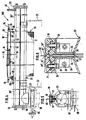
- the suction device designated 100 as a whole in FIG. 1 serves to dehumidify or drain an air-permeable Toobahn W. It comprises a screen cylinder 10, which has a length of up to 3.6 m and a transverse dimension of Can have 300 to 450 mm and from a wire mesh 11 (Fig. 4), which is shown in Figs. 1 and 3 by one Dashing should be indicated and its properties still to be described.
- the length extends through the screen cylinder 10 a suction chamber designated as a whole by 20, which in the 1 apparent from angled sheet metal profiles 21 is joined together and an octagonal inner cross section has whose "diameter" in the embodiment about 40% of the diameter of the screen cylinder Is 10.
- the suction chamber 20 forms one to be described Way, a suction slot 40, which is located in Fig. 1 above is.
- the limits of the suction slot 20 consist of Sliders 31 made of a suitable plastic.
- the screen cylinder 10 slides across the length of the screen cylinder 10 reaching suction slot 40 over the sliders 31, 31.
- Inside the screen cylinder 10 are symmetrical arranged to the suction slot 40 two support rollers 1, 2, the axially outside of the screen cylinder 10 in Machine frame are stored and on the inner circumference of the Roll off the screen cylinder 10.
- In the embodiment form the through the axes of the support rollers 1, 2 and Axis A of the suction chamber 20 planes an angle of about 150 ° with each other.
- the distance from the mouth of the Suction slot 40 to axis A and the distance from the lines of contact of the screen cylinder 10 on the outer circumference of the Support rollers 1, 2 to axis A are approximately the same.
- the screen cylinder 10 is through the support in the area of the suction slot 40 and on the two support rollers 1, 2 in the middle guided on a kind of three-point bearing.
- the fabric web W in the exemplary embodiment a knitted fabric web, comes wet from a treatment bath from below and runs at 13 on the outer circumference of the screen cylinder on.
- the web W then runs over an approximately 90 ° Circumferential portion of the screen cylinder 10 before reached the suction slot 40, at which by a to the Suction chamber 20 connected pump air through the web W is sucked through, the moisture contained therein takes away, which can be removed from the suction chamber 20.
- the support in the area of the suction slot 40 and through the two support rollers 1, 2 guide the screen cylinder 10 in the direction perpendicular to its longitudinal direction Flat, but not in the longitudinal direction.
- a radially projecting collar 6 is provided against which the there lies the front edge 10 'of the screen cylinder.
- the edge 10 'of the wire mesh forming the screen cylinder 10 is welded and smoothed.
- a fret 6 either at both ends of one Support roller may be provided or it must be at one end of the Screen cylinder 10 on a support roller a collar 6 and the other end of the screen cylinder 10 a collar 6 on the other support roller 2 may be attached.
- the screen cylinder 10 is a cylinder in mathematical terms Senses insofar as its generating all parallel to running along a certain straight line. But he doesn't have one certain cross-section, especially no rigid circular cross-section. There is also no dimensional stability of the Sieve cylinder 10 supporting reinforcement rings or the like.
- the screen cylinder 10 is rather exclusively from the wire mesh 11 and is easily deformable, i.e. it can be squeezed by hand in the transverse direction will. It is not completely limp, but still has a certain rigidity, so that a Sieve cylinders of 2 to 3.6 m in length and a "diameter" from 300 to 450 mm just standing upright can.
- the material of the wire mesh forming the screen cylinder 10 11 is corrosion-resistant steel with a diameter of 0.3 mm.
- the tissue from this wire is designed so that in the exemplary embodiment an opening percentage of 70% gives what the efficiency of suction through the suction slot 40 is beneficial. Nevertheless, the wire mesh is 11 beaten pretty close, so the support points corresponding to the web W close together.
- the screen cylinder has 10 in none installed in the suction device 100 Circular cross section, but a cross section in shape of a triangle with very rounded corners.
- the screen cylinder 10 lies on the sliders 31 at corners, that limit the suction slot 40, in the other two "Corners" on the outer circumference of the support rollers 1, 2 there.
- the leadership is such that in the screen cylinder 10 hardly There is tension in the circumferential direction and the screen cylinder 10 not pulled tight around the support rollers 1, 2 is. The latter would cause the screen cylinder 10 under a belt sprocket of approximately 120 ° the support rollers 1, 2 plant, for which a considerable longitudinal tensile force would be spent in the screen cylinder.
- the screen cylinder 10 is quite loose around the Suction slot 40 limiting components and the support rollers 1, 2 guided, so that starting from a force-free state, in which the screen cylinder 10 essentially by itself assumes a circular cross section, just that from FIG. 1 apparent approximate triangular shape.
- the contact forces on the support rollers 1, 2 are not zero, but not very high either. It results in a low "wrap angle" 15 (Fig. 1), which in the Embodiment is approximately 15 ° and does not exceed 30 ° should, otherwise the tensile stress in the circumferential direction gets correspondingly higher and problems with the lateral gradient forces occur.
- the screen cylinder 10 should therefore just be loosely guided around the support rollers 1, 2, that its longitudinal guide is shown in Fig. 2 simple way, so without swiveling and can do the same - but not completely free of forces, because in the case of an external rotary drive one the support rollers 1, 2 a certain torque transmission should be possible.
- Fig. 1 the support rollers 1, 2 are not driven.
- the Driving the screen cylinder 10 and the rotation of the support rollers 1, 2 are carried out exclusively by the web W. Due to the presence of the screen cylinder 10 is a such entrainment possible over the suction slot 40, without inadmissible longitudinal tensile stresses in the web W. are recorded.
- the web W comes out of a treatment bath soaking wet from below, but first runs over one driven spreader roller 3 to a tendency to Counteract curling. From the spreader roller 3, the web W goes almost directly to the scope a drainage roller 4 over against the outside the screen cylinder 10 rests at a point where inside a support roller 2 ', which is the location of the Support roller 2 in Fig. 1 takes, but is driven. The Material web W thus runs together with the screen cylinder 10 between the support roller 2 and the dewatering roller 4 formed nip 5.
- nip 5 is the web W of the main amount of the entrained Water, especially surface water, frees and runs after leaving the nip 5 in pre-dehumidified Condition over an approximately 120 ° circumferential section of the screen cylinder 10 before the suction slot reached in which the final dehumidification takes place, by the previous removal of the bulk the water in the roll gap 5 more uniform and penetrating can go on.
- One of the support rollers 1, 2 can also be driven if without the roll gap 5 being formed and an spreader roll 3 is present.
- a drive of one of the support rollers 1, 2 reduces that of the web W for the circulation of the Sieve cylinder 10 forces to be practically up to Zero.
- the web W is carried along by the screen cylinder 10 and passes through the suction slot 40 without arising of forces in the area of the web W.
- the ends of the suction chamber 20 protrude from the sieve cylinder 20 ' 10 before and is outside of the screen cylinder 10 suitable, indicated only by dash-dotted lines in FIG. 4 Supports 22 supported in the machine frame. At the ends is the suction chamber through flanged cover plates 23 sealed for the purpose of cleaning the suction chamber 20 can be removed.
- the suction chamber 20 has the Fig. 1 apparent closed octagon cross-section. in the middle range, i.e. over the length of the screen cylinder 10, however, has the suction chamber 20 according to FIGS. 4 to 6 upwardly extending mutually parallel wall parts 24 on that are rectangular at their upper edges wear outward bends 25 each. Between the mutually parallel wall parts 24 (FIG. 6) are extending over the length of the screen cylinder 10 Flat bars 26, 26 are provided between the ends another flat iron 27 which grips the width of the determined between the flat iron 26, 26 formed suction gap and at the same time serves stabilization, in so far it is connected to a transverse link 28, which means Screws 29 on the top of the suction chamber 20 Supports 30 is attached.
- the sliders 31 for the Screen cylinder 10 attached from a suitable, low-friction and wear-resistant plastic, the length of the bends 25 between the support 30 extend and in the manner shown in Fig. 6 are fastened by screws 32 to the bends 25.
- the sliders 31 leave a gap between them that forms the suction slot 40.
- In the facing each other End faces 31 'of the sliders 31 are over the Length of the sliders 31 parallel to their upper sliding surface 31 '' extending triangular grooves 33 are provided, which with assembled sliders 31 to a square add free cross section, in which on each End of the suction slot 40 precisely fitting limiting rods 34 sit to limit the suction slot 40 in Serve width direction of the web W.
- the boundary bars 34 are by means of so-called Bowden trains 35 in the Grooves 33 slidable in their longitudinal direction by the exit width of the suction slot 40 to the web width adapt.
- Suction nozzle 36 At the left end of the suction chamber 20 in FIG arranged perpendicular to the longitudinal extent of the suction chamber 20 Suction nozzle 36 provided, the cross section of which is quite is large and approximately one in the exemplary embodiment Third of the cross section of the suction chamber 20 is and the one connected to a vacuum pump via flanges 37 Line 38 is connected. Between the flanges 37 is a flap valve designated as a whole by 39 arranged with which the suction effect is interrupted can be. The pressure in the suction chamber 20 is dependent controllable according to the desired dehumidification effect and can be measured on a measuring nozzle 41.
Landscapes
- Engineering & Computer Science (AREA)
- Textile Engineering (AREA)
- Mechanical Engineering (AREA)
- General Engineering & Computer Science (AREA)
- Treatment Of Fiber Materials (AREA)
- Filtering Of Dispersed Particles In Gases (AREA)
- Manipulator (AREA)
- Branching, Merging, And Special Transfer Between Conveyors (AREA)
- Massaging Devices (AREA)
Applications Claiming Priority (2)
| Application Number | Priority Date | Filing Date | Title |
|---|---|---|---|
| DE29708262U | 1997-05-09 | ||
| DE29708262U DE29708262U1 (de) | 1997-05-09 | 1997-05-09 | Saugvorrichtung |
Publications (3)
| Publication Number | Publication Date |
|---|---|
| EP0877115A2 true EP0877115A2 (fr) | 1998-11-11 |
| EP0877115A3 EP0877115A3 (fr) | 1999-10-20 |
| EP0877115B1 EP0877115B1 (fr) | 2002-08-28 |
Family
ID=8040105
Family Applications (1)
| Application Number | Title | Priority Date | Filing Date |
|---|---|---|---|
| EP98107580A Expired - Lifetime EP0877115B1 (fr) | 1997-05-09 | 1998-04-25 | Dispositif d'aspiration |
Country Status (2)
| Country | Link |
|---|---|
| EP (1) | EP0877115B1 (fr) |
| DE (2) | DE29708262U1 (fr) |
Cited By (2)
| Publication number | Priority date | Publication date | Assignee | Title |
|---|---|---|---|---|
| CN105463725A (zh) * | 2016-01-28 | 2016-04-06 | 广州睿联电气科技有限公司 | 尼龙管吸水机 |
| CN108468222A (zh) * | 2017-07-18 | 2018-08-31 | 杭州安杰诺智能机械有限公司 | 真空吸排机及其使用方法 |
Family Cites Families (4)
| Publication number | Priority date | Publication date | Assignee | Title |
|---|---|---|---|---|
| DE2000436A1 (de) * | 1970-01-07 | 1971-07-15 | Jwi Ltd | Als Aussendecke einer Trockentrommel geeignetes Drahtgewebe und mit demselben ausgeruestete Trockentrommel |
| DE2403815A1 (de) * | 1974-01-26 | 1975-08-07 | Kuesters Eduard | Verfahren zur behandlung von textil-, vlies- und aehnlichen bahnen |
| DE2419061A1 (de) * | 1974-04-20 | 1975-11-06 | Artos Meier Windhorst Kg | Absaugvorrichtung fuer spannungsempfindliche warenbahnen |
| DE2723085C2 (de) * | 1977-05-21 | 1983-06-30 | Kleinewefers Gmbh, 4150 Krefeld | Gewebtes endloses Andrück- und Führungsband für mit einer Drehtrommel verseheneTextilbehandlungsvorrichtungen wie Transferdruckmaschinen, Dämpfkalander od. dgl. |
-
1997
- 1997-05-09 DE DE29708262U patent/DE29708262U1/de not_active Expired - Lifetime
-
1998
- 1998-04-25 DE DE59805283T patent/DE59805283D1/de not_active Expired - Fee Related
- 1998-04-25 EP EP98107580A patent/EP0877115B1/fr not_active Expired - Lifetime
Cited By (2)
| Publication number | Priority date | Publication date | Assignee | Title |
|---|---|---|---|---|
| CN105463725A (zh) * | 2016-01-28 | 2016-04-06 | 广州睿联电气科技有限公司 | 尼龙管吸水机 |
| CN108468222A (zh) * | 2017-07-18 | 2018-08-31 | 杭州安杰诺智能机械有限公司 | 真空吸排机及其使用方法 |
Also Published As
| Publication number | Publication date |
|---|---|
| DE59805283D1 (de) | 2002-10-02 |
| EP0877115B1 (fr) | 2002-08-28 |
| EP0877115A3 (fr) | 1999-10-20 |
| DE29708262U1 (de) | 1998-09-17 |
Similar Documents
| Publication | Publication Date | Title |
|---|---|---|
| DE2954326C2 (de) | Vorrichtung zum offenend-spinnen eines fadens | |
| DE2139159B2 (de) | Vorrichtung zum Breitstrecken von Warenbahnen, insbesondere von Papierbahnen | |
| DE1461127A1 (de) | Vorrichtung zum Entwaessern von Zellulose- und Kartonbahnen u.dgl. | |
| CH693214A5 (de) | Vorrichtung zum Verdichten eines verstreckten Faserverbandes. | |
| CH693340A5 (de) | Transportband zumTransportieren eines zu verdichtendenFaserverbandes. | |
| EP0877115B1 (fr) | Dispositif d'aspiration | |
| DE2626262C2 (de) | Doppelsiebpapiermaschine | |
| DE3205360A1 (de) | Verfahren und vorrichtung zum auswechseln eines pick-up-tuches und/oder eines presstuches der pressenpartie einer papiermaschine | |
| DE102005020165A1 (de) | Tauch-Quetschwalzwerk-Vorrichtung | |
| DE6584C (de) | Neuerungen für Roll- und Bogen-Calander | |
| EP1870515B1 (fr) | Assise de machine | |
| DE10030500A1 (de) | Spinnmaschine mit Verdichtungeinrichtung | |
| DE3834039A1 (de) | Querbandanordnung am ausgang einer karde | |
| EP0769465A2 (fr) | Bobineuse à cylindres porteurs | |
| DE10039732A1 (de) | Vorrichtung zum Verdichten eines Faserverbandes | |
| DE2604016A1 (de) | Einfaedelvorrichtung fuer eine oberbaulose falschdrall-texturiermaschine | |
| DE3127916A1 (de) | "vorrichtung zur nassbehandlung von geweben" | |
| CH631676A5 (de) | Fadenfuehrung an einem spulengatter. | |
| EP3978661A1 (fr) | Manchon perforé | |
| DE2931990C2 (de) | Vorrichtung zur Verweilbehandlung von bahnförmigem Textilgut | |
| DE1295349B (de) | Papiermaschine | |
| DE10029301A1 (de) | Transportband zum Transportieren eines zu verdichtenden Faserverbandes | |
| DE29704620U1 (de) | Roll-Sauge | |
| CH712229B1 (de) | Wickeldorn sowie Handtuchspender und Verfahren zu seinem Betrieb. | |
| DE69214945T2 (de) | Abdichtungselemente für den durchgang von geweben in einem kontinuierlich arbeitenden autoklav |
Legal Events
| Date | Code | Title | Description |
|---|---|---|---|
| PUAI | Public reference made under article 153(3) epc to a published international application that has entered the european phase |
Free format text: ORIGINAL CODE: 0009012 |
|
| AK | Designated contracting states |
Kind code of ref document: A2 Designated state(s): CH DE IT LI NL |
|
| AX | Request for extension of the european patent |
Free format text: AL;LT;LV;MK;RO;SI |
|
| PUAL | Search report despatched |
Free format text: ORIGINAL CODE: 0009013 |
|
| AK | Designated contracting states |
Kind code of ref document: A3 Designated state(s): AT BE CH CY DE DK ES FI FR GB GR IE IT LI LU MC NL PT SE |
|
| AX | Request for extension of the european patent |
Free format text: AL;LT;LV;MK;RO;SI |
|
| 17P | Request for examination filed |
Effective date: 19991112 |
|
| AKX | Designation fees paid |
Free format text: CH DE IT LI NL |
|
| 17Q | First examination report despatched |
Effective date: 20010613 |
|
| GRAG | Despatch of communication of intention to grant |
Free format text: ORIGINAL CODE: EPIDOS AGRA |
|
| GRAG | Despatch of communication of intention to grant |
Free format text: ORIGINAL CODE: EPIDOS AGRA |
|
| GRAH | Despatch of communication of intention to grant a patent |
Free format text: ORIGINAL CODE: EPIDOS IGRA |
|
| GRAH | Despatch of communication of intention to grant a patent |
Free format text: ORIGINAL CODE: EPIDOS IGRA |
|
| GRAA | (expected) grant |
Free format text: ORIGINAL CODE: 0009210 |
|
| AK | Designated contracting states |
Kind code of ref document: B1 Designated state(s): CH DE IT LI NL |
|
| REG | Reference to a national code |
Ref country code: CH Ref legal event code: EP |
|
| REG | Reference to a national code |
Ref country code: CH Ref legal event code: NV Representative=s name: R. A. EGLI & CO. PATENTANWAELTE |
|
| REF | Corresponds to: |
Ref document number: 59805283 Country of ref document: DE Date of ref document: 20021002 |
|
| PLBE | No opposition filed within time limit |
Free format text: ORIGINAL CODE: 0009261 |
|
| STAA | Information on the status of an ep patent application or granted ep patent |
Free format text: STATUS: NO OPPOSITION FILED WITHIN TIME LIMIT |
|
| 26N | No opposition filed |
Effective date: 20030530 |
|
| PGFP | Annual fee paid to national office [announced via postgrant information from national office to epo] |
Ref country code: NL Payment date: 20040427 Year of fee payment: 7 |
|
| PGFP | Annual fee paid to national office [announced via postgrant information from national office to epo] |
Ref country code: CH Payment date: 20050427 Year of fee payment: 8 |
|
| PGFP | Annual fee paid to national office [announced via postgrant information from national office to epo] |
Ref country code: DE Payment date: 20050430 Year of fee payment: 8 |
|
| PG25 | Lapsed in a contracting state [announced via postgrant information from national office to epo] |
Ref country code: NL Free format text: LAPSE BECAUSE OF NON-PAYMENT OF DUE FEES Effective date: 20051101 |
|
| NLV4 | Nl: lapsed or anulled due to non-payment of the annual fee |
Effective date: 20051101 |
|
| PG25 | Lapsed in a contracting state [announced via postgrant information from national office to epo] |
Ref country code: LI Free format text: LAPSE BECAUSE OF NON-PAYMENT OF DUE FEES Effective date: 20060430 Ref country code: CH Free format text: LAPSE BECAUSE OF NON-PAYMENT OF DUE FEES Effective date: 20060430 |
|
| PGFP | Annual fee paid to national office [announced via postgrant information from national office to epo] |
Ref country code: IT Payment date: 20060430 Year of fee payment: 9 |
|
| PG25 | Lapsed in a contracting state [announced via postgrant information from national office to epo] |
Ref country code: DE Free format text: LAPSE BECAUSE OF NON-PAYMENT OF DUE FEES Effective date: 20061101 |
|
| REG | Reference to a national code |
Ref country code: CH Ref legal event code: PL |
|
| PG25 | Lapsed in a contracting state [announced via postgrant information from national office to epo] |
Ref country code: IT Free format text: LAPSE BECAUSE OF NON-PAYMENT OF DUE FEES Effective date: 20070425 |