EP0877221A2 - Mit mehreren Röhren gefertigter Wärmetauscher - Google Patents
Mit mehreren Röhren gefertigter Wärmetauscher Download PDFInfo
- Publication number
- EP0877221A2 EP0877221A2 EP98108350A EP98108350A EP0877221A2 EP 0877221 A2 EP0877221 A2 EP 0877221A2 EP 98108350 A EP98108350 A EP 98108350A EP 98108350 A EP98108350 A EP 98108350A EP 0877221 A2 EP0877221 A2 EP 0877221A2
- Authority
- EP
- European Patent Office
- Prior art keywords
- wall surface
- cap
- inside wall
- tank portion
- tank
- Prior art date
- Legal status (The legal status is an assumption and is not a legal conclusion. Google has not performed a legal analysis and makes no representation as to the accuracy of the status listed.)
- Granted
Links
- 238000005219 brazing Methods 0.000 claims abstract description 35
- 239000000463 material Substances 0.000 claims abstract description 26
- 238000003780 insertion Methods 0.000 claims description 4
- 230000037431 insertion Effects 0.000 claims description 4
- 239000012530 fluid Substances 0.000 claims description 3
- 239000003507 refrigerant Substances 0.000 description 19
- XAGFODPZIPBFFR-UHFFFAOYSA-N aluminium Chemical compound [Al] XAGFODPZIPBFFR-UHFFFAOYSA-N 0.000 description 7
- 239000012071 phase Substances 0.000 description 7
- CURLTUGMZLYLDI-UHFFFAOYSA-N Carbon dioxide Chemical compound O=C=O CURLTUGMZLYLDI-UHFFFAOYSA-N 0.000 description 6
- 238000001816 cooling Methods 0.000 description 6
- 239000007791 liquid phase Substances 0.000 description 5
- 238000000034 method Methods 0.000 description 5
- 229910052782 aluminium Inorganic materials 0.000 description 4
- 229910002092 carbon dioxide Inorganic materials 0.000 description 3
- 239000001569 carbon dioxide Substances 0.000 description 3
- 239000011162 core material Substances 0.000 description 3
- 230000000149 penetrating effect Effects 0.000 description 3
- 239000011555 saturated liquid Substances 0.000 description 3
- 230000006835 compression Effects 0.000 description 2
- 238000007906 compression Methods 0.000 description 2
- 230000006866 deterioration Effects 0.000 description 2
- 229910018125 Al-Si Inorganic materials 0.000 description 1
- 229910018520 Al—Si Inorganic materials 0.000 description 1
- 239000003638 chemical reducing agent Substances 0.000 description 1
- 238000005253 cladding Methods 0.000 description 1
- 230000007423 decrease Effects 0.000 description 1
- 230000002542 deteriorative effect Effects 0.000 description 1
- 238000010438 heat treatment Methods 0.000 description 1
- 239000007788 liquid Substances 0.000 description 1
- 230000004048 modification Effects 0.000 description 1
- 238000012986 modification Methods 0.000 description 1
Images

Classifications
-
- F—MECHANICAL ENGINEERING; LIGHTING; HEATING; WEAPONS; BLASTING
- F28—HEAT EXCHANGE IN GENERAL
- F28D—HEAT-EXCHANGE APPARATUS, NOT PROVIDED FOR IN ANOTHER SUBCLASS, IN WHICH THE HEAT-EXCHANGE MEDIA DO NOT COME INTO DIRECT CONTACT
- F28D1/00—Heat-exchange apparatus having stationary conduit assemblies for one heat-exchange medium only, the media being in contact with different sides of the conduit wall, in which the other heat-exchange medium is a large body of fluid, e.g. domestic or motor car radiators
- F28D1/02—Heat-exchange apparatus having stationary conduit assemblies for one heat-exchange medium only, the media being in contact with different sides of the conduit wall, in which the other heat-exchange medium is a large body of fluid, e.g. domestic or motor car radiators with heat-exchange conduits immersed in the body of fluid
- F28D1/04—Heat-exchange apparatus having stationary conduit assemblies for one heat-exchange medium only, the media being in contact with different sides of the conduit wall, in which the other heat-exchange medium is a large body of fluid, e.g. domestic or motor car radiators with heat-exchange conduits immersed in the body of fluid with tubular conduits
- F28D1/053—Heat-exchange apparatus having stationary conduit assemblies for one heat-exchange medium only, the media being in contact with different sides of the conduit wall, in which the other heat-exchange medium is a large body of fluid, e.g. domestic or motor car radiators with heat-exchange conduits immersed in the body of fluid with tubular conduits the conduits being straight
- F28D1/0535—Heat-exchange apparatus having stationary conduit assemblies for one heat-exchange medium only, the media being in contact with different sides of the conduit wall, in which the other heat-exchange medium is a large body of fluid, e.g. domestic or motor car radiators with heat-exchange conduits immersed in the body of fluid with tubular conduits the conduits being straight the conduits having a non-circular cross-section
- F28D1/05366—Assemblies of conduits connected to common headers, e.g. core type radiators
- F28D1/05391—Assemblies of conduits connected to common headers, e.g. core type radiators with multiple rows of conduits or with multi-channel conduits combined with a particular flow pattern, e.g. multi-row multi-stage radiators
-
- F—MECHANICAL ENGINEERING; LIGHTING; HEATING; WEAPONS; BLASTING
- F28—HEAT EXCHANGE IN GENERAL
- F28F—DETAILS OF HEAT-EXCHANGE AND HEAT-TRANSFER APPARATUS, OF GENERAL APPLICATION
- F28F9/00—Casings; Header boxes; Auxiliary supports for elements; Auxiliary members within casings
- F28F9/02—Header boxes; End plates
- F28F9/0202—Header boxes having their inner space divided by partitions
- F28F9/0204—Header boxes having their inner space divided by partitions for elongated header box, e.g. with transversal and longitudinal partitions
- F28F9/0209—Header boxes having their inner space divided by partitions for elongated header box, e.g. with transversal and longitudinal partitions having only transversal partitions
- F28F9/0212—Header boxes having their inner space divided by partitions for elongated header box, e.g. with transversal and longitudinal partitions having only transversal partitions the partitions being separate elements attached to header boxes
-
- F—MECHANICAL ENGINEERING; LIGHTING; HEATING; WEAPONS; BLASTING
- F28—HEAT EXCHANGE IN GENERAL
- F28F—DETAILS OF HEAT-EXCHANGE AND HEAT-TRANSFER APPARATUS, OF GENERAL APPLICATION
- F28F9/00—Casings; Header boxes; Auxiliary supports for elements; Auxiliary members within casings
- F28F9/02—Header boxes; End plates
- F28F9/0243—Header boxes having a circular cross-section
-
- F—MECHANICAL ENGINEERING; LIGHTING; HEATING; WEAPONS; BLASTING
- F28—HEAT EXCHANGE IN GENERAL
- F28D—HEAT-EXCHANGE APPARATUS, NOT PROVIDED FOR IN ANOTHER SUBCLASS, IN WHICH THE HEAT-EXCHANGE MEDIA DO NOT COME INTO DIRECT CONTACT
- F28D21/00—Heat-exchange apparatus not covered by any of the groups F28D1/00 - F28D20/00
- F28D2021/0019—Other heat exchangers for particular applications; Heat exchange systems not otherwise provided for
- F28D2021/0068—Other heat exchangers for particular applications; Heat exchange systems not otherwise provided for for refrigerant cycles
- F28D2021/0073—Gas coolers
-
- F—MECHANICAL ENGINEERING; LIGHTING; HEATING; WEAPONS; BLASTING
- F28—HEAT EXCHANGE IN GENERAL
- F28F—DETAILS OF HEAT-EXCHANGE AND HEAT-TRANSFER APPARATUS, OF GENERAL APPLICATION
- F28F2220/00—Closure means, e.g. end caps on header boxes or plugs on conduits
-
- Y—GENERAL TAGGING OF NEW TECHNOLOGICAL DEVELOPMENTS; GENERAL TAGGING OF CROSS-SECTIONAL TECHNOLOGIES SPANNING OVER SEVERAL SECTIONS OF THE IPC; TECHNICAL SUBJECTS COVERED BY FORMER USPC CROSS-REFERENCE ART COLLECTIONS [XRACs] AND DIGESTS
- Y10—TECHNICAL SUBJECTS COVERED BY FORMER USPC
- Y10S—TECHNICAL SUBJECTS COVERED BY FORMER USPC CROSS-REFERENCE ART COLLECTIONS [XRACs] AND DIGESTS
- Y10S165/00—Heat exchange
- Y10S165/454—Heat exchange having side-by-side conduits structure or conduit section
- Y10S165/471—Plural parallel conduits joined by manifold
- Y10S165/488—Header is rounded in cross section, e.g. circular, oval
-
- Y—GENERAL TAGGING OF NEW TECHNOLOGICAL DEVELOPMENTS; GENERAL TAGGING OF CROSS-SECTIONAL TECHNOLOGIES SPANNING OVER SEVERAL SECTIONS OF THE IPC; TECHNICAL SUBJECTS COVERED BY FORMER USPC CROSS-REFERENCE ART COLLECTIONS [XRACs] AND DIGESTS
- Y10—TECHNICAL SUBJECTS COVERED BY FORMER USPC
- Y10T—TECHNICAL SUBJECTS COVERED BY FORMER US CLASSIFICATION
- Y10T29/00—Metal working
- Y10T29/49—Method of mechanical manufacture
- Y10T29/4935—Heat exchanger or boiler making
- Y10T29/49389—Header or manifold making
Definitions
- the present invention relates to a heat exchanger for a refrigerating system where carbon dioxide (CO 2 ), as a refrigerant, is used in a super-critical region of a refrigerating cycle.
- CO 2 carbon dioxide
- JP-B-7-18602 discloses a vapor compression type refrigerating cycle (CO 2 -refrigeranting cycle) where carbon dioxide (CO 2 ) is used as a refrigerant in place of fleon.
- the CO 2 -refrigeranting cycle operates in the same manner as the conventional vapor compression type refrigerating cycle does where the fleon is used as a refrigerant. That is, as denoted by A-B-C-D-A in FIG. 7 (Mollier chart of the CO 2 -refrigerating cycle), gas-phase CO 2 is compressed (A-B) by a compressor to high-temperature and high-pressure super-critical phase CO 2 , and the super-critical phase CO 2 is cooled (B-C) by a heat emitter (gas cooler).
- the super-critical phase CO 2 is pressure-reduced (C-D) by a pressure reducer to a gas-liquid phase CO 2 , and the gas-liquid phase CO 2 is evaporated (D-A) by an evaporator while cooling an outside fluid by absorbing heat from the outside fluid.
- the CO 2 changes from super-critical phase to gas-liquid phase when the pressure thereof becomes to be under a saturated liquid pressure (pressure at a cross point between a segment CD and a saturated liquid line in FIG. 7).
- a saturated liquid pressure pressure at a cross point between a segment CD and a saturated liquid line in FIG. 7.
- the CO 2 changes from a condition (C) to a condition (D) slowly, the CO 2 changes from the super-critical phase to the gas-liquid phase via liquid phase.
- the molecule of CO 2 moves as in the gas phase while the density of CO 2 is substantially the same as the liquid-density thereof.
- the critical temperature of CO 2 is about 31 °C, which is lower than that of fleon (for example, the critical temperature of R12 is 112 °C).
- the critical temperature of R12 is 112 °C.
- the condition (C) of CO 2 at the outlet side of the heat emitter depends on the pressure of CO 2 discharged by the compressor and the temperature of CO 2 at the outlet side of the heat emitter. As the outside air temperature cannot be controlled, the CO 2 temperature at the outlet side of the heat emitter cannot be controlled.
- condition (C) can be controlled by only controlling a discharge pressure in the compressor (CO 2 pressure at the outlet side of the heat emitter). That is, when the outside air temperature is high in summer or the like, the CO 2 pressure at the outlet side of the heat emitter needs to be raised as denoted by E-F-G-H-E in FIG. 7, for attaining a sufficient cooling performance (enthalpy difference).
- the maximum CO 2 pressure in the CO 2 -refrigerating cycle is about ten times as high as that in the conventional refrigerating cycle where the fleon is used as refrigerant.
- JP-U-63-54979 discloses a heat exchanger in which the end portion of a header tank is formed into a semi-sphere shape. The strength of the end portion of this header tank is high.
- this heat exchanger is formed by stacking plural thin plates of a predetermined shape, and by brazing them together. Thus, as this heat exchanger has many connecting portions, and the pressure strength thereof is not sufficient in view of entire heat exchanger.
- An object of the present invention is to provide a heating heat exchanger, in which each connecting portion is brazed firmly for attaining a high pressure-strength.
- a first connecting portion (cap-gap) between a cap and a tank portion is separated away from a second connecting portion (tube-gap) between the tank portion and a tube by a predetermined distance.
- the brazing material is suctioned into both connecting portions (both gaps) sufficiently, and both connecting portions are brazed firmly.
- the high pressure-strength is attained in the entire heat exchanger.
- a columnar like-inside space is formed in a tank portion, and an inside wall surface of the cap includes a spherical surface. That is, the inside wall surface of the cap is connected tangentially and smoothly (without a sharp corner) to the inside wall surface of the tank portion.
- a stress concentration is reduced at the connecting portion, thereby increasing the pressure-strength of a header tank formed by the cap and the tank portion.
- an outer shape of the header tank is formed into a columnar shape both ends of which are flat covered. Therefore, the thickness of the end corner portion of the header tank is large, thereby increasing the strength of the header tank to an outer force acting the cap from the outside.
- a heat exchanger according to the present invention is applied to a heat emitter 1 in a refrigerating cycle where carbon dioxide (CO 2 ) is used as a refrigerant to provide a CO 2 -refrigerating cycle.
- CO 2 carbon dioxide
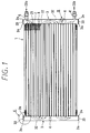
- the heat emitter 1 includes a core portion 2 carrying out heat exchange between the refrigerant (CO 2 ) and air.
- the core portion 2 includes a plurality of tubes 21 made of aluminum (A1100) through which the refrigerant flows, and a plurality of cooling fins 22 disposed between the adjacent tubes 21.
- the cooling fin 22 is made of aluminum (A3003) and formed into a corrugate shape.
- the tubes 21 and the cooling fins 22 are brazed integrally by Al-Si brazing material clad on both surfaces of the cooling fins 22.
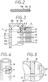
- each tube 21 as shown in FIG. 2, a plurality of refrigerant passages 21a penetrating in the longitudinal direction of the tube 21 are formed by an extruding process.
- the refrigerant passage 21a is formed into a rectangular shape in cross section the corner of which is rounded for enlarging a cross sectional-area, and relieving a stress concentration.
- Header tanks 3 are provided at both side ends of the plural tubes 21 in the longitudinal direction thereof.
- the header tank 3 has an inside space 31 with which the tubes 21 (refrigerant passages 21a) communicate as shown in FIG. 3, and extends in a direction perpendicular to the longitudinal direction of the tube 21.
- the header tank 3 is constructed by a columnar tank portion 32 forming the columnar shaped inside space 31, and a cap 33 covering both ends of the tank portion 32 in the longitudinal direction thereof.
- the tubes 21 are inserted into the insertion holes 32c (FIG. 5) penetrating the tank portion 32 in the thickness direction thereof.
- the inside wall surface 33a of the cap 33, facing the inside space 31, is formed into a spherical surface, and the outside wall surface 33b thereof is formed into a flat shape perpendicular to the longitudinal direction of the tank portion 32 (header tank 3).
- the tank portion 32 is made of aluminum (A3003) and formed by a drawing process, and the brazing material is clad on the inside wall surface 32a of the tank portion 32.
- the cap 33 is made of aluminum and formed by a carving process or a die-cast method.
- the tube 21 is inserted into the tank portion 32 while penetrating the insertion hole 32c, and brazed integrally to the tank portion 32 as well as the cap 33 by the brazing material clad on the inside wall surface 32a of the tank portion 32.
- a connecting portion "A" between the inside wall surface 33a of the cap 33 and the inside wall surface 32a of the tank portion 32 is separated away from a connecting portion "B" between the outside wall surface 21b of the tube 21 (FIG. 2) and the inside wall surface 32a of the tank portion 32 by a predetermined distance L, as shown in FIG. 3.
- the predetermined distance L is 0.5 times more than the thickness t of the tank portion 32. In the present embodiment, the distance L is about 3 mm.
- the inside space 31 of the header tank 3 (tank portion 32) is partitioned into plural spaces by separators 4.
- the separators 4 are brazed to both inside and outside wall surfaces 32a, 32b of the tank portion 32, as shown in FIG. 4.
- a refrigerant inlet pipe 5 is provided at the upper portion of the tank portion 32.
- the refrigerant inlet pipe 5 is connected to the discharge port of a compressor (not illustrated) in the CO 2 -refrigerating cycle.
- a refrigerant outlet pipe 6 is provided at the lower portion of the tank portion 32.
- the refrigerant outlet pipe 6 is connected to the inlet port of a pressure reducing member of the CO 2 -refrigerating cycle.
- a solid-line arrow and a broken-line arrow denote flows of the refrigerant (CO 2 ).
- the inside space 31 is formed into a shape the inside surface of which is formed by a curved surface without a sharp corner. That is, the inside wall surface 33a of the cap 33 is connected tangentially and smoothly to the inside wall surface 32a of the tank portion 32. Thus, the stress concentration is reduced at the connecting portion, thereby increasing the pressure-strength of the tank portion 32.
- the heat emitter 1 there are only two connecting portions influenced by an inside refrigerant pressure, which are a connecting portion between the tube 21 and the tank portion 32, and a connecting portion between the cap 33 and the tank portion 32.
- the heat emitter is constructed by stacking and brazing a plurality of thin plates formed into a predetermined shape. That is, there are more connecting portions than that in the present embodiment. Therefore, when the prior art heat emitter is carried on a vehicle which tends to vibrate, because a vibrating force is added to a refrigerant (CO 2 ) pressure, the pressure-strength of the heat emitter decreases.
- CO 2 refrigerant
- the pressure-strength of each the tube 21, the tank portion 32, and the cap 33 is large, and the connecting portions influenced by the inside pressure are only two portions as above described.
- a high pressure-strength is attained entirely in comparison with that in the prior art heat emitter.
- the connecting portion A and the connecting portion B are placed at the same position, i.e., the distance L is 0 (zero)
- most of the brazing material clad on the inside wall surface 32a of the tank portion 32 is suctioned into a cap-gap (a minute gap between the cap 33 and the inside wall surface 32a of the tank portion 32) by a capillary action thereof during the brazing operation.
- the brazing material is hardly suctioned into a tube-gap (a minute gap between the outside wall surface 21a of the tube 21 and the insertion hole 32c of the tank portion 32) and stored in the tube-gap.
- the brazing material flows into the tube-gap insufficiently, and a brazing deterioration may occur between tube 21 and the header tank 3.
- the brazing material clad between these connecting portions A, B is suctioned into the tube-gap also by a capillary action of the tube-gap.
- the brazing material flows into the tube-gap sufficiently, thereby brazing the tube 21 to the header tank 3 firmly.
- the outside wall surface 33b of the cap 33 is formed into the flat shape perpendicular to the longitudinal direction of the tank portion 32, that is, the outer shape of the header tank 3 is formed into a columnar-like shape both ends of which are flat covered. Therefore, the thickness of the end corner portions 3a (FIG. 1) of the header tank 3 are large, thereby increasing the strength of the header tank 3 to an outer force acting on the cap 33 from the outside.
- the brazing material is clad on the inside wall surface 32a of the tank portion 32, the brazing material can be clad while the tank portion 32 is formed by the drawing process.
- the brazing material is clad easily in comparison with that the brazing material is clad on the tube 21 or the cap 33.
- the present invention is not limited to the heat exchanger in which the brazing material is clad on the inside wall surface 32a of the tank portion 32, and may be applied to a heat exchanger in which the brazing material is clad on the outside wall surface 21a of the tube 21.
- the brazing material when the brazing material is clad on the outside wall surface 21a of the tube 21, the brazing material is not clad on the tank portion 32 which contacts the tube 21 for preventing the core material clad with the brazing material from being eroded by the brazing material during the brazing operation.
- the brazing material clad on the outside wall surface 21a of the tube 21 is suctioned not only into the tube-gap, but also into the cap-gap.
- an amount of the brazing material in the tube-gap is reduced, thereby deteriorating the brazing performance in the tube-gap.
- the connecting portion A is distant from the connection portion B, the brazing material is suppressed from being suctioned into the cap-gap, thereby preventing the deterioration of the brazing performance in the tube-gap.
- the brazing operation of the cap-gap is done by cladding the brazing material on the outside wall surface 33b of the cap 33, or by putting an O-ring like brazing material on the top portion of the tank portion 32.
- the outer shape of the header tank 3 may be like a prism both ends of which are flat.
- the inside wall surface 33a of the cap 33 is formed by only the spherical surface.
- the inside wall surface 33a may be formed by a spherical surface and a plane surface, in which the inside wall surface 33a of the cap 33 is connected smoothly to the inside wall surface 32a of the tank portion 32a through a circular arc.
Landscapes
- Engineering & Computer Science (AREA)
- Physics & Mathematics (AREA)
- Thermal Sciences (AREA)
- Mechanical Engineering (AREA)
- General Engineering & Computer Science (AREA)
- Details Of Heat-Exchange And Heat-Transfer (AREA)
- Heat-Exchange Devices With Radiators And Conduit Assemblies (AREA)
Applications Claiming Priority (3)
| Application Number | Priority Date | Filing Date | Title |
|---|---|---|---|
| JP11965497A JP3508465B2 (ja) | 1997-05-09 | 1997-05-09 | 熱交換器 |
| JP119654/97 | 1997-05-09 | ||
| JP11965497 | 1997-05-09 |
Publications (4)
| Publication Number | Publication Date |
|---|---|
| EP0877221A2 true EP0877221A2 (de) | 1998-11-11 |
| EP0877221A3 EP0877221A3 (de) | 2000-01-12 |
| EP0877221B1 EP0877221B1 (de) | 2002-07-24 |
| EP0877221B2 EP0877221B2 (de) | 2006-01-04 |
Family
ID=14766789
Family Applications (1)
| Application Number | Title | Priority Date | Filing Date |
|---|---|---|---|
| EP98108350A Expired - Lifetime EP0877221B2 (de) | 1997-05-09 | 1998-05-07 | Mit mehreren Röhren gefertigter Wärmetauscher |
Country Status (4)
| Country | Link |
|---|---|
| US (1) | US5924485A (de) |
| EP (1) | EP0877221B2 (de) |
| JP (1) | JP3508465B2 (de) |
| DE (1) | DE69806683T3 (de) |
Cited By (3)
| Publication number | Priority date | Publication date | Assignee | Title |
|---|---|---|---|---|
| WO2001061263A1 (en) * | 2000-02-15 | 2001-08-23 | Zexel Valeo Climate Control Corporation | Heat exchanger |
| FR2808320A1 (fr) * | 2000-04-27 | 2001-11-02 | Valeo Thermique Moteur Sa | Echangeur de chaleur a haute pression pour circuit de climatisation, notamment de vehicule automobile |
| EP1046524A3 (de) * | 1999-04-23 | 2002-05-08 | Valeo Klimatechnik GmbH | Hockdruckgaskühler für einen Kühlmittelkreislauf einer Kraftfahrzeugklimaanlage |
Families Citing this family (10)
| Publication number | Priority date | Publication date | Assignee | Title |
|---|---|---|---|---|
| JP2002013896A (ja) * | 2000-06-27 | 2002-01-18 | Zexel Valeo Climate Control Corp | 熱交換器 |
| JP2002048421A (ja) | 2000-08-01 | 2002-02-15 | Matsushita Electric Ind Co Ltd | 冷凍サイクル装置 |
| JP2002139290A (ja) * | 2000-10-31 | 2002-05-17 | Toyo Radiator Co Ltd | モジュールタイプ熱交換器およびその製造方法 |
| JP4767408B2 (ja) * | 2000-12-26 | 2011-09-07 | 株式会社ヴァレオジャパン | 熱交換器 |
| JP4094806B2 (ja) * | 2000-12-28 | 2008-06-04 | カルソニックカンセイ株式会社 | 熱交換器の製造方法 |
| US6964296B2 (en) * | 2001-02-07 | 2005-11-15 | Modine Manufacturing Company | Heat exchanger |
| WO2004074757A1 (ja) * | 2003-02-19 | 2004-09-02 | Zexel Valeo Climate Control Corporation | 熱交換器 |
| US7303003B2 (en) * | 2004-12-24 | 2007-12-04 | Showa Denko K.K. | Heat exchanger |
| JP4852304B2 (ja) * | 2005-12-14 | 2012-01-11 | 昭和電工株式会社 | 熱交換器 |
| JP5736761B2 (ja) * | 2010-12-20 | 2015-06-17 | 富士電機株式会社 | 熱交換器 |
Citations (2)
| Publication number | Priority date | Publication date | Assignee | Title |
|---|---|---|---|---|
| JPS6354979U (de) | 1986-09-26 | 1988-04-13 | ||
| JPH0718602B2 (ja) | 1989-01-09 | 1995-03-06 | シンヴェント・アクシェセルスカープ | 超臨界蒸気圧縮サイクルの運転方法およびその装置 |
Family Cites Families (10)
| Publication number | Priority date | Publication date | Assignee | Title |
|---|---|---|---|---|
| US4308652A (en) * | 1978-02-10 | 1982-01-05 | Karmazin Products Corporation | Heat exchanger construction |
| JPH0356630Y2 (de) * | 1986-09-30 | 1991-12-19 | ||
| US5245836A (en) * | 1989-01-09 | 1993-09-21 | Sinvent As | Method and device for high side pressure regulation in transcritical vapor compression cycle |
| FR2652145B1 (fr) † | 1989-09-18 | 1994-03-04 | Valtubes | Reservoir metallique pour fluides a haute pression. |
| EP0586037B1 (de) * | 1992-09-03 | 1997-05-21 | Modine Manufacturing Company | Wärmetauscher |
| US5481800A (en) * | 1993-11-24 | 1996-01-09 | Wynn's Climate Systems, Inc. | Method of making a parallel flow condenser with lap joined headers |
| DE4402927B4 (de) † | 1994-02-01 | 2008-02-14 | Behr Gmbh & Co. Kg | Kondensator für eine Klimaanlage eines Fahrzeuges |
| FR2734047B1 (fr) * | 1995-05-10 | 1997-06-13 | Valeo Thermique Moteur Sa | Echangeur de chaleur, en particulier condenseur de climatisation pour vehicule automobile |
| US5607012A (en) * | 1995-06-12 | 1997-03-04 | General Motors Corporation | Heat exchanger |
| US5947196A (en) * | 1998-02-09 | 1999-09-07 | S & Z Tool & Die Co., Inc. | Heat exchanger having manifold formed of stamped sheet material |
-
1997
- 1997-05-09 JP JP11965497A patent/JP3508465B2/ja not_active Expired - Fee Related
-
1998
- 1998-05-07 US US09/074,529 patent/US5924485A/en not_active Expired - Fee Related
- 1998-05-07 DE DE69806683T patent/DE69806683T3/de not_active Expired - Fee Related
- 1998-05-07 EP EP98108350A patent/EP0877221B2/de not_active Expired - Lifetime
Patent Citations (2)
| Publication number | Priority date | Publication date | Assignee | Title |
|---|---|---|---|---|
| JPS6354979U (de) | 1986-09-26 | 1988-04-13 | ||
| JPH0718602B2 (ja) | 1989-01-09 | 1995-03-06 | シンヴェント・アクシェセルスカープ | 超臨界蒸気圧縮サイクルの運転方法およびその装置 |
Cited By (3)
| Publication number | Priority date | Publication date | Assignee | Title |
|---|---|---|---|---|
| EP1046524A3 (de) * | 1999-04-23 | 2002-05-08 | Valeo Klimatechnik GmbH | Hockdruckgaskühler für einen Kühlmittelkreislauf einer Kraftfahrzeugklimaanlage |
| WO2001061263A1 (en) * | 2000-02-15 | 2001-08-23 | Zexel Valeo Climate Control Corporation | Heat exchanger |
| FR2808320A1 (fr) * | 2000-04-27 | 2001-11-02 | Valeo Thermique Moteur Sa | Echangeur de chaleur a haute pression pour circuit de climatisation, notamment de vehicule automobile |
Also Published As
| Publication number | Publication date |
|---|---|
| DE69806683D1 (de) | 2002-08-29 |
| EP0877221B2 (de) | 2006-01-04 |
| DE69806683T2 (de) | 2003-05-08 |
| DE69806683T3 (de) | 2006-08-24 |
| JPH10311697A (ja) | 1998-11-24 |
| EP0877221A3 (de) | 2000-01-12 |
| EP0877221B1 (de) | 2002-07-24 |
| JP3508465B2 (ja) | 2004-03-22 |
| US5924485A (en) | 1999-07-20 |
Similar Documents
| Publication | Publication Date | Title |
|---|---|---|
| EP0877221B1 (de) | Mit mehreren Röhren gefertigter Wärmetauscher | |
| US6973805B2 (en) | Layered heat exchanger, layered evaporator for motor vehicle air conditioners and refrigeration system | |
| AU2002238890A1 (en) | Layered heat exchanger, layered evaporator for motor vehicle air conditioners and refrigeration system | |
| US5540278A (en) | Heat exchanger | |
| JP2002206890A (ja) | 熱交換器およびこれを用いた冷凍空調サイクル装置 | |
| JPH10238896A (ja) | 積層型蒸発器 | |
| JPH109713A (ja) | 冷媒凝縮装置、および冷媒凝縮器 | |
| JP2004530092A5 (de) | ||
| JP4222137B2 (ja) | 放熱器 | |
| US7174953B2 (en) | Stacking-type, multi-flow, heat exchanger | |
| EP1096210A2 (de) | Abscheider/Sammler und Verfahren zur Herstellung desselben | |
| JPH0814702A (ja) | 積層型蒸発器 | |
| JP5540816B2 (ja) | 蒸発器ユニット | |
| JP2001133075A (ja) | 冷凍回路の熱交換器 | |
| US20040104016A1 (en) | Heat exchanger | |
| JP3812021B2 (ja) | 積層型熱交換器 | |
| JP2006003071A (ja) | 熱交換器 | |
| JPH0518635A (ja) | 冷媒蒸発器 | |
| JP2000105093A (ja) | 熱交換器 | |
| JP2005061667A (ja) | 熱交換器 | |
| KR20040017323A (ko) | 열 교환기 | |
| JP4081883B2 (ja) | 熱交換器 | |
| JPH10170188A (ja) | 熱交換器 | |
| CN113899115B (zh) | 水-制冷剂换热装置及微型制冷系统 | |
| CN221005577U (zh) | 冷凝器、冷媒循环系统 |
Legal Events
| Date | Code | Title | Description |
|---|---|---|---|
| PUAI | Public reference made under article 153(3) epc to a published international application that has entered the european phase |
Free format text: ORIGINAL CODE: 0009012 |
|
| AK | Designated contracting states |
Kind code of ref document: A2 Designated state(s): DE FR GB |
|
| AX | Request for extension of the european patent |
Free format text: AL;LT;LV;MK;RO;SI |
|
| PUAL | Search report despatched |
Free format text: ORIGINAL CODE: 0009013 |
|
| AK | Designated contracting states |
Kind code of ref document: A3 Designated state(s): AT BE CH CY DE DK ES FI FR GB GR IE IT LI LU MC NL PT SE |
|
| AX | Request for extension of the european patent |
Free format text: AL;LT;LV;MK;RO;SI |
|
| 17P | Request for examination filed |
Effective date: 20000322 |
|
| AKX | Designation fees paid |
Free format text: DE FR GB |
|
| 17Q | First examination report despatched |
Effective date: 20010202 |
|
| GRAG | Despatch of communication of intention to grant |
Free format text: ORIGINAL CODE: EPIDOS AGRA |
|
| GRAG | Despatch of communication of intention to grant |
Free format text: ORIGINAL CODE: EPIDOS AGRA |
|
| GRAH | Despatch of communication of intention to grant a patent |
Free format text: ORIGINAL CODE: EPIDOS IGRA |
|
| GRAH | Despatch of communication of intention to grant a patent |
Free format text: ORIGINAL CODE: EPIDOS IGRA |
|
| GRAA | (expected) grant |
Free format text: ORIGINAL CODE: 0009210 |
|
| AK | Designated contracting states |
Kind code of ref document: B1 Designated state(s): DE FR GB |
|
| REG | Reference to a national code |
Ref country code: GB Ref legal event code: FG4D |
|
| REF | Corresponds to: |
Ref document number: 69806683 Country of ref document: DE Date of ref document: 20020829 |
|
| ET | Fr: translation filed | ||
| PLBI | Opposition filed |
Free format text: ORIGINAL CODE: 0009260 |
|
| PLBQ | Unpublished change to opponent data |
Free format text: ORIGINAL CODE: EPIDOS OPPO |
|
| PLBF | Reply of patent proprietor to notice(s) of opposition |
Free format text: ORIGINAL CODE: EPIDOS OBSO |
|
| 26 | Opposition filed |
Opponent name: BEHR GMBH & CO. KG Effective date: 20030424 |
|
| PLAX | Notice of opposition and request to file observation + time limit sent |
Free format text: ORIGINAL CODE: EPIDOSNOBS2 |
|
| PLBB | Reply of patent proprietor to notice(s) of opposition received |
Free format text: ORIGINAL CODE: EPIDOSNOBS3 |
|
| REG | Reference to a national code |
Ref country code: GB Ref legal event code: 746 Effective date: 20040406 |
|
| PUAH | Patent maintained in amended form |
Free format text: ORIGINAL CODE: 0009272 |
|
| STAA | Information on the status of an ep patent application or granted ep patent |
Free format text: STATUS: PATENT MAINTAINED AS AMENDED |
|
| 27A | Patent maintained in amended form |
Effective date: 20060104 |
|
| AK | Designated contracting states |
Kind code of ref document: B2 Designated state(s): DE FR GB |
|
| ET3 | Fr: translation filed ** decision concerning opposition | ||
| PGFP | Annual fee paid to national office [announced via postgrant information from national office to epo] |
Ref country code: FR Payment date: 20090515 Year of fee payment: 12 Ref country code: DE Payment date: 20090429 Year of fee payment: 12 |
|
| PGFP | Annual fee paid to national office [announced via postgrant information from national office to epo] |
Ref country code: GB Payment date: 20090506 Year of fee payment: 12 |
|
| GBPC | Gb: european patent ceased through non-payment of renewal fee |
Effective date: 20100507 |
|
| REG | Reference to a national code |
Ref country code: FR Ref legal event code: ST Effective date: 20110131 |
|
| PG25 | Lapsed in a contracting state [announced via postgrant information from national office to epo] |
Ref country code: DE Free format text: LAPSE BECAUSE OF NON-PAYMENT OF DUE FEES Effective date: 20101201 |
|
| PG25 | Lapsed in a contracting state [announced via postgrant information from national office to epo] |
Ref country code: FR Free format text: LAPSE BECAUSE OF NON-PAYMENT OF DUE FEES Effective date: 20100531 |
|
| PG25 | Lapsed in a contracting state [announced via postgrant information from national office to epo] |
Ref country code: GB Free format text: LAPSE BECAUSE OF NON-PAYMENT OF DUE FEES Effective date: 20100507 |