EP0877344A1 - Sicherheitszaun aus leitenden Gittern - Google Patents
Sicherheitszaun aus leitenden Gittern Download PDFInfo
- Publication number
- EP0877344A1 EP0877344A1 EP98460011A EP98460011A EP0877344A1 EP 0877344 A1 EP0877344 A1 EP 0877344A1 EP 98460011 A EP98460011 A EP 98460011A EP 98460011 A EP98460011 A EP 98460011A EP 0877344 A1 EP0877344 A1 EP 0877344A1
- Authority
- EP
- European Patent Office
- Prior art keywords
- grids
- grid
- cables
- trellis
- security fence
- Prior art date
- Legal status (The legal status is an assumption and is not a legal conclusion. Google has not performed a legal analysis and makes no representation as to the accuracy of the status listed.)
- Granted
Links
Images


Classifications
-
- E—FIXED CONSTRUCTIONS
- E04—BUILDING
- E04H—BUILDINGS OR LIKE STRUCTURES FOR PARTICULAR PURPOSES; SWIMMING OR SPLASH BATHS OR POOLS; MASTS; FENCING; TENTS OR CANOPIES, IN GENERAL
- E04H17/00—Fencing, e.g. fences, enclosures, corrals
- E04H17/017—Fencing provided with electric elements or components, e.g. fencing member or component, such as fence strands, post, panel or rail, provided with electric elements or components
-
- E—FIXED CONSTRUCTIONS
- E04—BUILDING
- E04H—BUILDINGS OR LIKE STRUCTURES FOR PARTICULAR PURPOSES; SWIMMING OR SPLASH BATHS OR POOLS; MASTS; FENCING; TENTS OR CANOPIES, IN GENERAL
- E04H17/00—Fencing, e.g. fences, enclosures, corrals
- E04H17/14—Fences constructed of rigid elements, e.g. with additional wire fillings or with posts
- E04H17/16—Fences constructed of rigid elements, e.g. with additional wire fillings or with posts using prefabricated panel-like elements, e.g. wired frames
- E04H17/161—Fences constructed of rigid elements, e.g. with additional wire fillings or with posts using prefabricated panel-like elements, e.g. wired frames using wire panels
-
- G—PHYSICS
- G08—SIGNALLING
- G08B—SIGNALLING SYSTEMS, e.g. PERSONAL CALLING SYSTEMS; ORDER TELEGRAPHS; ALARM SYSTEMS
- G08B13/00—Burglar, theft or intruder alarms
- G08B13/02—Mechanical actuation
- G08B13/12—Mechanical actuation by the breaking or disturbance of stretched cords or wires
- G08B13/122—Mechanical actuation by the breaking or disturbance of stretched cords or wires for a perimeter fence
Definitions
- the present invention relates to a security fence consisting of trellis. conductors which is intended to allow signaling of any attempt break-in by sectioning one of its sections.
- the security fences based on conductive mesh which are currently used to prevent unauthorized persons from entering facilities or sensitive areas have the following structure.
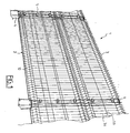
- FIG. 1 An example of a known fence is shown in FIG. 1, which is attached to this description.
- the fence 1 visible in this FIG. consists of 2 wire mesh plasticized 3 which are stretched between posts 4.
- Each trellis 2 is constituted by vertical cables 3a and by horizontal cables 3b welded on the previous ones, such so that said cables 3 define meshes of rectangular shape.
- Posts 4 are provided with flanges 5 for holding the vertical cables 3a and therefore with said trellis 2 in the same plane.
- the vertical and horizontal cables 3a and 3b are respectively known as weft cables and shore cables by man of career.
- each cable 3 is for example obtained by embedding in a plastic coating 6, on the one hand, a first conductive strand 7 and, on the other hand, a second conductive strand 8 which is covered with an insulating layer 9 and which is secured to said first strand 7.
- the plastic coating 6 makes it possible to electrically insulate the conductive strands 7 and 8 vis-à-vis the outside and make them invisible to evil people intentional, so that cutting one of the cables 3 implies necessarily that of the two strands 7 and 8 which it contains.
- each trellis 2 of cables 3 has horizontal bands 10 in rib shape in various heights of the fence 1 and over the entire length thereof (see Fig. 1). These strips 10 are provided to give increased robustness to said closure 1.
- the conductive strands 7 and 8 are usually connected, on the one hand, to a source power supply and, on the other hand, to an alarm system connected to the terminals a resistive circuit (said source, said system and said circuit are not represented).
- This warning system is intended to signal any modification of the intensity of the current flowing through said resistive circuit which would be due to the sectioning of one of the cables 3 of the fence 1.
- the object of the present invention is to provide a security fence consisting of conductive mesh, said fence being provided to allow the reporting of any attempted break-in by sectioning a section of said section trellis, which overcomes the aforementioned drawback while being obtained by an easy process to implement, therefore inexpensive.
- a security fence according to the invention is such that each trellis consists of two grids of the same shape which are assembled one on the other in superposition, in such a way that the elementary meshes of one of the grids coincide with those of the other grid, said grids being mutually isolated electrically.
- each trellis comprises at least two electrically conductive means which are in contact respectively electric with said grids and which are provided to maintain said grids in one on top of the other.
- each grid is consisting of an assembly of vertical and horizontal cables, each cable horizontal of a grid being welded to said vertical cables on the same side of these last, the two grids being assembled one on the other at their respective sides which do not include said horizontal cables.
- one of the two grids has an insulating coating, except in an area including said means conductor of electricity in contact with said grid, the other grid not being isolated electrically, except in an area which is such that one of said areas overlaps the other.
- each of the two grids constituting each trellis consists of a plurality of metal cables, bent and of circular section, two adjacent cables of the same grid being welded by points in their curved parts.
- each trellis comprises means for securing said grids with one another, in areas which are between two adjacent welding points of each grid.
- each of the two grids constituting each trellis is made of expanded metal, so that each grid has diamond-shaped mesh skylights with edges of rectangular section.
- one of the two grids has a insulating coating over its entire surface, the other grid not being insulated electrically.
- a fence according to a first embodiment of the invention (see Fig. 3) consists of a plurality of identical panels or mesh 20 which are each mounted between two connection posts 21 (these posts 21 are shown symbolically in FIG. 4), for example.
- each fence panel 20 is essentially consisting of two grids 30 and 40 of the same shape and dimensions identical which are mounted one on the other in superposition by means of joining means 50 and 50 '.
- each panel 20 has in its external part an electrically insulating layer 60 of plastic material.
- Each grid 30, 40 is constituted by an assembly of metal cables vertical and horizontal 31 and 32, 41 and 42, which assembly forms a plurality of elementary meshes of rectangular shape. As shown in FIG. 3, the the elementary meshes of one of the grids 30 coincide with those of the other grid 40.
- the cables 31, 32, 41, 42 are for example made of galvanized steel, and they have a circular section.
- Each horizontal cable 32, 42 of a grid 30, 40 is welded to several vertical cables 31, 41, on the same side of the latter.
- the spacing between two adjacent horizontal cables 32, 42 is greater than that between two adjacent vertical cables 31, 41, for the same grid 30, 40.
- These spacings can for example be 5 cm and 20 respectively cm.
- the two grids 30 and 40 of each panel 20 differ only one from the other by the nature of their external surface.
- One of the grids 40 includes an insulating coating 43 of plastic material, except on the surface of one of its horizontal cables 42a and on that of the cables vertical 41 which extends only in the immediate vicinity of said horizontal cable 42a. There is shown in FIG. 3 zone 44 of grid 40 which is not isolated electrically.
- the external surface of the other grid 30 merges with that of the wall 33 of the metallic cables 31, 32 which constitute it, except on an area 34 of said grid 30 which is electrically insulated by means of a plastic coating 35.
- Said zone 34 and the metal zone 44 of the grid 40 are provided to overlap each other during the superimposition of the two grids 30 and 40, so their respective vertical metallic cables 31 and 41 are not in contact with each other with each other.
- the securing means 50 and 50 'provided to hold the grids 30 and 40 of each panel 20 in a superimposed position are for example constituted U-shaped profiles that conduct electricity.
- Each profile 50 or 50 ' is mounted around a pair of horizontal cables 32 and 42 or 42a opposite belonging respectively to said grids 30 and 40 so as to be only in contact, via one of its wings 51, with that of the two cables horizontal 32, 42a which is not electrically isolated.
- each profile 50 or 50 ′ has notches 52 which are practiced at regular intervals along its length, this on one of its wings 51 and on a part of its core 53.
- Each notch 52 is designed to receive two cables vertical 31 and 41 of the two grids 30 and 40 which are juxtaposed.
- each notch 52 has a rounded contour on the core 53 of the corresponding profile 50 or 50 ', so as to match said vertical cables 31 and 41 of circular section.
- Each profile 50 or 50 ' is provided with means 54 to hold it in place around the two horizontal cables 32 and 42 or 42a which it is intended to surround.
- These holding means 54 are for example made up of legs in the shape of an inverted V which are provided to extend under said cables 32 and 42 or 42a. Legs 54 are connected by their respective vertices to said profile 50 or 50 ', via rivets 55 which are mounted through the core 53 of said profile 50 or 50 'over the length of the latter and between the two cables 32 and 42 or 42a (see also Fig. 5).
- the fence panels 20 are connected, on the one hand, to an electrical power source 70 and, on the other hand, to a circuit resistant 80 at the terminals of which is mounted a warning system 90 provided for report any change in the intensity of the current flowing through said resistive circuit 80.
- a warning system 90 provided for report any change in the intensity of the current flowing through said resistive circuit 80.
- the two grids 30 and 40 constituting each panel 20 are shown separately for the sake of clarity.
- the horizontal cables 32 and 42, 42a of the grids 30 and 40 each belonging to two adjacent panels 20 are electrically connected to each other via of each connection post 21.
- the electric power source 70 is for example made up of a autotransformer whose terminals 71 and 72 are respectively connected to the grids 30 and 40 of the fence via two of the securing means 50 and 50 ' (see Fig. 3).
- the latter which are respectively in electrical contact with the two grids 30 and 40, constitute the terminals for connecting the fence with said source 70 and said resistor circuit 80, so that the grids 30 and 40 of the fence are mutually characterized by a potential difference, which is predetermined by the characteristics of said source 70.
- said grids 30 and 40 can be electrified independently of one another.
- the resistor circuit 80 is connected, on the one hand, to the midpoint 73 of the autotransformer 70 and, on the other hand, the two grids 30 and 40 of the fencing.
- warning system 90 it consists for example of one or several lamps.
- the fence according to this first embodiment of the invention operates from the following way.
- This structure with two grids 30 and 40 for each fence panel 20 according to the invention allows to give said fence increased mechanical strength compared to the prior art, due to the two separate grids 30 and 40 which constitute.
- the structure of the fence according to the invention does not include protruding strip 10 in the form of a rib to reinforce it, unlike many of prior art fencing, which does not add to its cost.
- FIG. 6 There is shown schematically in FIG. 6 a second embodiment of a fence according to the invention.
- each of the two grids 130 or 140 constituting each panel or trellis 120 consists of a plurality of metallic cables 131 or 141, bent and similarly circular section.
- Each cable is for example of the type presenting successively identical curvatures in opposite directions.
- Said cables 131 or 141 of the same grid 130 or 140 are welded two to two in parallel directions. More specifically, two cables 131 or 141 adjacent are spot welded to the respective vertices S of their curvatures which are placed one against the other, so as to obtain a plane grid 130 or 140 entirely metallic.
- One of the two grids 140 thus obtained is plasticized over all of its surface, unlike the other, which is not electrically isolated.
- each grid 130 or 140 of a fence panel 120 is connected to at least two conductive means, on the one hand, to electrically connect the grids 130 and 140 belonging to each other to two adjacent panels 120 and, on the other hand, to connect said panels of fence 120 to said current source 70 and to the warning system 90 mounted at resistive circuit terminals 80.
- each securing means 150 is for example constituted by a clip made of material plastic which is intended to press on the cables 131 and 141 of the two grids 130 and 140.
- said conductive means could also be used to keep the two grids 130 and 140 superimposed one over the other.
- the two grids 130 and 140 and the means which assemble them are then coated. one against the other with an electrically insulating layer 160 of plastic.
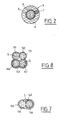
- FIG. 8 There is shown in FIG. 8 a cross-sectional view along the points solder S of each grid. We see here that the insulating layer 160 covers around from said solder points S the two pairs of cables 131, 141 which belong respectively to the two grids 130 and 140.
- the fence according to this second embodiment works in a way identical to that described in the first mode.
- the two grids 130 and 140 of a panel 120 being mutually electrically insulated, they can be electrified independently of each other.
- FIG. 9 There is shown schematically in FIG. 9 a third embodiment of a fence according to the invention.
- each of the two grids 230, 240 constituting each panel or fence mesh 220 is made of expanded metal.
- each grid 230 or 240 is made up of a network of shaped skylights rhombus, for example, whose respective edges 231 or 241 have a cross-section square (said edges 231 or 241 are shown in thin lines for reasons of clarity).
- the two grids 230 and 240 have been placed in superposition of so as to make the edges 231 and 241 of their skylights coincide, the two grids 230 and 240 with each other by suitable means (not shown), for example of the type of said means 150 in the form of a clip.
- said means of solidarity at least two in number, could be respectively in contact electric with the two grids 230 and 240.
- one of the two grids 240 has a coating insulating over its entire surface, while the other grid 230 is not insulated electrically.
- the assembly of the two grids 230 and 240 is then plasticized to ensure their electrical insulation.
Landscapes
- Engineering & Computer Science (AREA)
- Architecture (AREA)
- Civil Engineering (AREA)
- Structural Engineering (AREA)
- Physics & Mathematics (AREA)
- General Physics & Mathematics (AREA)
- Fencing (AREA)
- Laminated Bodies (AREA)
Applications Claiming Priority (2)
| Application Number | Priority Date | Filing Date | Title |
|---|---|---|---|
| FR9705686A FR2762919B1 (fr) | 1997-04-30 | 1997-04-30 | Cloture de securite constituee de treillis conducteurs |
| FR9705686 | 1997-04-30 |
Publications (2)
| Publication Number | Publication Date |
|---|---|
| EP0877344A1 true EP0877344A1 (de) | 1998-11-11 |
| EP0877344B1 EP0877344B1 (de) | 2002-11-06 |
Family
ID=9506709
Family Applications (1)
| Application Number | Title | Priority Date | Filing Date |
|---|---|---|---|
| EP98460011A Expired - Lifetime EP0877344B1 (de) | 1997-04-30 | 1998-04-30 | Sicherheitszaun aus leitenden Gittern |
Country Status (5)
| Country | Link |
|---|---|
| EP (1) | EP0877344B1 (de) |
| AT (1) | ATE227456T1 (de) |
| DE (1) | DE69809115T2 (de) |
| ES (1) | ES2185132T3 (de) |
| FR (1) | FR2762919B1 (de) |
Cited By (3)
| Publication number | Priority date | Publication date | Assignee | Title |
|---|---|---|---|---|
| FR2849253A1 (fr) * | 2002-12-24 | 2004-06-25 | Vigifrance Securite Sa | Cloture de securite |
| EP2178055A1 (de) | 2008-10-20 | 2010-04-21 | Eurocloture | Sicherheitsverschlusspaneel und Sicherheitsverschluss, der mindestens aus einem solchen Paneel besteht |
| EP3032003A1 (de) * | 2014-12-10 | 2016-06-15 | Société Rhodanienne d'Electronique Appliquée | Sicherheitszaun, der mehrere feststehende paneele auf einem skelettbau umfasst |
Families Citing this family (1)
| Publication number | Priority date | Publication date | Assignee | Title |
|---|---|---|---|---|
| DE202013100055U1 (de) * | 2013-01-07 | 2013-02-08 | Nikolaus Berlemann | Zaungitter, Zaun und Halteelement oder -profil |
Citations (2)
| Publication number | Priority date | Publication date | Assignee | Title |
|---|---|---|---|---|
| FR2463245A1 (fr) * | 1979-08-07 | 1981-02-20 | Ci Ka Ra Srl | Reseau de cloture anti-effraction en forme de grillage ainsi que procede pour sa fabrication |
| DE3101708A1 (de) * | 1981-01-21 | 1982-08-26 | Horst Thomas Drahtzaunbau & Baustoffgrosshandlung, 4630 Bochum | Sicherheitszaun zur einfriedung von besonders gefaehrdeten objekten |
-
1997
- 1997-04-30 FR FR9705686A patent/FR2762919B1/fr not_active Expired - Fee Related
-
1998
- 1998-04-30 DE DE69809115T patent/DE69809115T2/de not_active Expired - Lifetime
- 1998-04-30 ES ES98460011T patent/ES2185132T3/es not_active Expired - Lifetime
- 1998-04-30 AT AT98460011T patent/ATE227456T1/de not_active IP Right Cessation
- 1998-04-30 EP EP98460011A patent/EP0877344B1/de not_active Expired - Lifetime
Patent Citations (2)
| Publication number | Priority date | Publication date | Assignee | Title |
|---|---|---|---|---|
| FR2463245A1 (fr) * | 1979-08-07 | 1981-02-20 | Ci Ka Ra Srl | Reseau de cloture anti-effraction en forme de grillage ainsi que procede pour sa fabrication |
| DE3101708A1 (de) * | 1981-01-21 | 1982-08-26 | Horst Thomas Drahtzaunbau & Baustoffgrosshandlung, 4630 Bochum | Sicherheitszaun zur einfriedung von besonders gefaehrdeten objekten |
Cited By (5)
| Publication number | Priority date | Publication date | Assignee | Title |
|---|---|---|---|---|
| FR2849253A1 (fr) * | 2002-12-24 | 2004-06-25 | Vigifrance Securite Sa | Cloture de securite |
| EP2178055A1 (de) | 2008-10-20 | 2010-04-21 | Eurocloture | Sicherheitsverschlusspaneel und Sicherheitsverschluss, der mindestens aus einem solchen Paneel besteht |
| FR2937360A1 (fr) * | 2008-10-20 | 2010-04-23 | Eurocloture | Panneau de cloture de securite et cloture de securite qui est constituee d'au moins un tel panneau |
| EP3032003A1 (de) * | 2014-12-10 | 2016-06-15 | Société Rhodanienne d'Electronique Appliquée | Sicherheitszaun, der mehrere feststehende paneele auf einem skelettbau umfasst |
| FR3029956A1 (fr) * | 2014-12-10 | 2016-06-17 | Soc Rhodanienne D'electronique Appliquee | Cloture de securite comprenant plusieurs panneaux fixes sur une ossature |
Also Published As
| Publication number | Publication date |
|---|---|
| EP0877344B1 (de) | 2002-11-06 |
| ES2185132T3 (es) | 2003-04-16 |
| ATE227456T1 (de) | 2002-11-15 |
| FR2762919B1 (fr) | 1999-08-06 |
| DE69809115T2 (de) | 2003-07-10 |
| FR2762919A1 (fr) | 1998-11-06 |
| DE69809115D1 (de) | 2002-12-12 |
Similar Documents
| Publication | Publication Date | Title |
|---|---|---|
| EP0330525B1 (de) | Vorgefertigte elektrische Kanalisation, anwendbar auf mehrere Nennströme vom Typ bestehend aus einem flachen kannelierten Isolationsträger für Leiterschienen | |
| CA1312294C (fr) | Tube pour la circulation d'un fluide inflammable, et tuyauterie realisee a partir de tels tubes | |
| EP0847690B1 (de) | Elektrische Vogelabwehrvorrichtung | |
| FR2561815A1 (fr) | Dispositif de protection contre les rayonnements pour des traversees de cables | |
| EP1145842A2 (de) | Verbundglasscheibe | |
| CA1289639C (fr) | Borne d'alimentation electrique pour vitrage encapsule | |
| EP0643399B1 (de) | Hochfrequenzübertragungskabel | |
| EP0877344B1 (de) | Sicherheitszaun aus leitenden Gittern | |
| EP1314355B1 (de) | Elektrische Vogelabschreckvorrichtung | |
| BE1019499A5 (fr) | Grille avec detection du sectionnement. | |
| EP0381583B1 (de) | Heizvorrichtung mittels Infrarotstrahlung, welche auf einer Mauer oder der Decke eines Gebäuderaumes befestigt ist | |
| EP1114582B1 (de) | Elektrozaun | |
| FR3098658A1 (fr) | Dispositif de connexion pour mettre à la terre un équipement électrique et/ou créer une liaison équipotentielle entre des éléments conducteurs | |
| EP0373553B1 (de) | Abgeschirmtes elektrisches Kabel, versehen mit Abzweig-Schnellverbindungszonen | |
| FR2704629A1 (fr) | Film chauffant à structure modulaire, pour chauffage par rayonnement, et dispositif pour sa connexion. | |
| EP0130097A1 (de) | Gewellt gewebtes Drahtgitter für Einbruchmeldung und Anwendungen dieses Drahtgitters | |
| EP2178055A1 (de) | Sicherheitsverschlusspaneel und Sicherheitsverschluss, der mindestens aus einem solchen Paneel besteht | |
| EP4000136A1 (de) | Elektrischer verbinder aus metall für flexible elektrisch leitende streifen und zugehörige leitende streifenverbinderanordnung | |
| EP0435782B1 (de) | Elektrische Zäune mit metallischen Leitungselementen aus einer binären Kupfer/Cadmium Legierung | |
| FR2725847A1 (fr) | Canalisation electrique a barres enrobees | |
| FR2765318A1 (fr) | Cible de tir a detection d'impact | |
| FR3010115A1 (fr) | Panneau composite fraise de cloture de securite et cloture ou protection specifique de securite qui sont constituees d'au moins un tel panneau | |
| FR2664092A1 (fr) | Fusible rapide perfectionne. | |
| FR2849253A1 (fr) | Cloture de securite | |
| FR3077594A1 (fr) | Dispositif de balisage des postes electriques d'un site industriel d'installation electrique |
Legal Events
| Date | Code | Title | Description |
|---|---|---|---|
| PUAI | Public reference made under article 153(3) epc to a published international application that has entered the european phase |
Free format text: ORIGINAL CODE: 0009012 |
|
| AK | Designated contracting states |
Kind code of ref document: A1 Designated state(s): AT BE CH DE DK ES FI FR GB GR IE IT LI LU NL PT SE |
|
| AX | Request for extension of the european patent |
Free format text: AL;LT;LV;MK;RO;SI |
|
| 17P | Request for examination filed |
Effective date: 19990421 |
|
| AKX | Designation fees paid |
Free format text: AT BE CH DE DK ES FI GB GR IE IT LI LU NL PT SE |
|
| RBV | Designated contracting states (corrected) |
Designated state(s): AT BE CH DE DK ES FI FR GB GR IE IT LI LU NL PT SE |
|
| RAP1 | Party data changed (applicant data changed or rights of an application transferred) |
Owner name: CHEMERY LAON ELECTRICITE S.A. |
|
| RIN1 | Information on inventor provided before grant (corrected) |
Inventor name: CHEMERY LAON ELECTRICITE S.A. |
|
| GRAG | Despatch of communication of intention to grant |
Free format text: ORIGINAL CODE: EPIDOS AGRA |
|
| 17Q | First examination report despatched |
Effective date: 20020131 |
|
| GRAG | Despatch of communication of intention to grant |
Free format text: ORIGINAL CODE: EPIDOS AGRA |
|
| GRAH | Despatch of communication of intention to grant a patent |
Free format text: ORIGINAL CODE: EPIDOS IGRA |
|
| GRAH | Despatch of communication of intention to grant a patent |
Free format text: ORIGINAL CODE: EPIDOS IGRA |
|
| GRAA | (expected) grant |
Free format text: ORIGINAL CODE: 0009210 |
|
| AK | Designated contracting states |
Kind code of ref document: B1 Designated state(s): AT BE CH DE DK ES FI FR GB GR IE IT LI LU NL PT SE |
|
| PG25 | Lapsed in a contracting state [announced via postgrant information from national office to epo] |
Ref country code: NL Free format text: LAPSE BECAUSE OF FAILURE TO SUBMIT A TRANSLATION OF THE DESCRIPTION OR TO PAY THE FEE WITHIN THE PRESCRIBED TIME-LIMIT Effective date: 20021106 Ref country code: IE Free format text: LAPSE BECAUSE OF FAILURE TO SUBMIT A TRANSLATION OF THE DESCRIPTION OR TO PAY THE FEE WITHIN THE PRESCRIBED TIME-LIMIT Effective date: 20021106 Ref country code: GR Free format text: LAPSE BECAUSE OF FAILURE TO SUBMIT A TRANSLATION OF THE DESCRIPTION OR TO PAY THE FEE WITHIN THE PRESCRIBED TIME-LIMIT Effective date: 20021106 Ref country code: FI Free format text: LAPSE BECAUSE OF FAILURE TO SUBMIT A TRANSLATION OF THE DESCRIPTION OR TO PAY THE FEE WITHIN THE PRESCRIBED TIME-LIMIT Effective date: 20021106 Ref country code: AT Free format text: LAPSE BECAUSE OF FAILURE TO SUBMIT A TRANSLATION OF THE DESCRIPTION OR TO PAY THE FEE WITHIN THE PRESCRIBED TIME-LIMIT Effective date: 20021106 |
|
| REF | Corresponds to: |
Ref document number: 227456 Country of ref document: AT Date of ref document: 20021115 Kind code of ref document: T |
|
| REG | Reference to a national code |
Ref country code: GB Ref legal event code: FG4D Free format text: NOT ENGLISH |
|
| REG | Reference to a national code |
Ref country code: CH Ref legal event code: NV Representative=s name: RIEDERER HASLER & PARTNER PATENTANWAELTE AG Ref country code: CH Ref legal event code: EP |
|
| REG | Reference to a national code |
Ref country code: IE Ref legal event code: FG4D Free format text: FRENCH |
|
| REF | Corresponds to: |
Ref document number: 69809115 Country of ref document: DE Date of ref document: 20021212 |
|
| GBT | Gb: translation of ep patent filed (gb section 77(6)(a)/1977) |
Effective date: 20021205 |
|
| PG25 | Lapsed in a contracting state [announced via postgrant information from national office to epo] |
Ref country code: SE Free format text: LAPSE BECAUSE OF FAILURE TO SUBMIT A TRANSLATION OF THE DESCRIPTION OR TO PAY THE FEE WITHIN THE PRESCRIBED TIME-LIMIT Effective date: 20030206 Ref country code: PT Free format text: LAPSE BECAUSE OF FAILURE TO SUBMIT A TRANSLATION OF THE DESCRIPTION OR TO PAY THE FEE WITHIN THE PRESCRIBED TIME-LIMIT Effective date: 20030206 Ref country code: DK Free format text: LAPSE BECAUSE OF FAILURE TO SUBMIT A TRANSLATION OF THE DESCRIPTION OR TO PAY THE FEE WITHIN THE PRESCRIBED TIME-LIMIT Effective date: 20030206 |
|
| NLV1 | Nl: lapsed or annulled due to failure to fulfill the requirements of art. 29p and 29m of the patents act | ||
| REG | Reference to a national code |
Ref country code: ES Ref legal event code: FG2A Ref document number: 2185132 Country of ref document: ES Kind code of ref document: T3 |
|
| REG | Reference to a national code |
Ref country code: IE Ref legal event code: FD4D Ref document number: 0877344E Country of ref document: IE |
|
| PLBE | No opposition filed within time limit |
Free format text: ORIGINAL CODE: 0009261 |
|
| STAA | Information on the status of an ep patent application or granted ep patent |
Free format text: STATUS: NO OPPOSITION FILED WITHIN TIME LIMIT |
|
| 26N | No opposition filed |
Effective date: 20030807 |
|
| PG25 | Lapsed in a contracting state [announced via postgrant information from national office to epo] |
Ref country code: FR Free format text: LAPSE BECAUSE OF NON-PAYMENT OF DUE FEES Effective date: 20031231 |
|
| REG | Reference to a national code |
Ref country code: FR Ref legal event code: ST |
|
| REG | Reference to a national code |
Ref country code: CH Ref legal event code: PLI Owner name: EUROCLOTURE SECURITY S.A.R.L. Free format text: CHEMERY LAON ELECTRICITE S.A.#10, RUE WINSTON CHURCHILL#LAON (AISNE) (FR) -TRANSFER TO- EUROCLOTURE SECURITY S.A.R.L.#1 R DU DAUPHINE#69120 VAULX-EN-VELIN (FR) |
|
| REG | Reference to a national code |
Ref country code: GB Ref legal event code: 732E Free format text: REGISTERED BETWEEN 20110120 AND 20110126 |
|
| PGFP | Annual fee paid to national office [announced via postgrant information from national office to epo] |
Ref country code: LU Payment date: 20110429 Year of fee payment: 14 |
|
| PGFP | Annual fee paid to national office [announced via postgrant information from national office to epo] |
Ref country code: DE Payment date: 20110421 Year of fee payment: 14 Ref country code: CH Payment date: 20110428 Year of fee payment: 14 Ref country code: ES Payment date: 20110426 Year of fee payment: 14 |
|
| REG | Reference to a national code |
Ref country code: ES Ref legal event code: GD2A Effective date: 20110816 |
|
| PGFP | Annual fee paid to national office [announced via postgrant information from national office to epo] |
Ref country code: GB Payment date: 20110421 Year of fee payment: 14 Ref country code: BE Payment date: 20110414 Year of fee payment: 14 |
|
| PGFP | Annual fee paid to national office [announced via postgrant information from national office to epo] |
Ref country code: IT Payment date: 20110422 Year of fee payment: 14 |
|
| BERE | Be: lapsed |
Owner name: S.A. *CHEMERY LAON ELECTRICITE Effective date: 20120430 |
|
| REG | Reference to a national code |
Ref country code: CH Ref legal event code: PL |
|
| GBPC | Gb: european patent ceased through non-payment of renewal fee |
Effective date: 20120430 |
|
| PG25 | Lapsed in a contracting state [announced via postgrant information from national office to epo] |
Ref country code: CH Free format text: LAPSE BECAUSE OF NON-PAYMENT OF DUE FEES Effective date: 20120430 Ref country code: GB Free format text: LAPSE BECAUSE OF NON-PAYMENT OF DUE FEES Effective date: 20120430 Ref country code: BE Free format text: LAPSE BECAUSE OF NON-PAYMENT OF DUE FEES Effective date: 20120430 Ref country code: LI Free format text: LAPSE BECAUSE OF NON-PAYMENT OF DUE FEES Effective date: 20120430 |
|
| REG | Reference to a national code |
Ref country code: DE Ref legal event code: R119 Ref document number: 69809115 Country of ref document: DE Effective date: 20121101 |
|
| PG25 | Lapsed in a contracting state [announced via postgrant information from national office to epo] |
Ref country code: IT Free format text: LAPSE BECAUSE OF NON-PAYMENT OF DUE FEES Effective date: 20120430 |
|
| REG | Reference to a national code |
Ref country code: ES Ref legal event code: FD2A Effective date: 20130715 |
|
| PG25 | Lapsed in a contracting state [announced via postgrant information from national office to epo] |
Ref country code: ES Free format text: LAPSE BECAUSE OF NON-PAYMENT OF DUE FEES Effective date: 20120501 |
|
| PG25 | Lapsed in a contracting state [announced via postgrant information from national office to epo] |
Ref country code: LU Free format text: LAPSE BECAUSE OF NON-PAYMENT OF DUE FEES Effective date: 20120430 |
|
| PG25 | Lapsed in a contracting state [announced via postgrant information from national office to epo] |
Ref country code: DE Free format text: LAPSE BECAUSE OF NON-PAYMENT OF DUE FEES Effective date: 20121101 |