EP0877368A2 - Plattenübertragungsvorrichtung - Google Patents
Plattenübertragungsvorrichtung Download PDFInfo
- Publication number
- EP0877368A2 EP0877368A2 EP98107904A EP98107904A EP0877368A2 EP 0877368 A2 EP0877368 A2 EP 0877368A2 EP 98107904 A EP98107904 A EP 98107904A EP 98107904 A EP98107904 A EP 98107904A EP 0877368 A2 EP0877368 A2 EP 0877368A2
- Authority
- EP
- European Patent Office
- Prior art keywords
- disk
- guide members
- transfer device
- loading
- disk guide
- Prior art date
- Legal status (The legal status is an assumption and is not a legal conclusion. Google has not performed a legal analysis and makes no representation as to the accuracy of the status listed.)
- Granted
Links
- 238000003780 insertion Methods 0.000 description 11
- 230000037431 insertion Effects 0.000 description 11
- 230000007246 mechanism Effects 0.000 description 10
- 230000003287 optical effect Effects 0.000 description 6
- 230000037361 pathway Effects 0.000 description 2
- 230000001154 acute effect Effects 0.000 description 1
- 238000012986 modification Methods 0.000 description 1
- 230000004048 modification Effects 0.000 description 1
- 230000000717 retained effect Effects 0.000 description 1
- 238000000926 separation method Methods 0.000 description 1
Images


Classifications
-
- G—PHYSICS
- G11—INFORMATION STORAGE
- G11B—INFORMATION STORAGE BASED ON RELATIVE MOVEMENT BETWEEN RECORD CARRIER AND TRANSDUCER
- G11B17/00—Guiding record carriers not specifically of filamentary or web form, or of supports therefor
- G11B17/02—Details
- G11B17/04—Feeding or guiding single record carrier to or from transducer unit
- G11B17/05—Feeding or guiding single record carrier to or from transducer unit specially adapted for discs not contained within cartridges
- G11B17/051—Direct insertion, i.e. without external loading means
- G11B17/0515—Direct insertion, i.e. without external loading means adapted for discs of different sizes
Definitions
- the present invention relates to a disk transfer device and, more particularly, to a disk transfer device which grips the outer edge of a disk during the disk transfer.
- Japanese patent application SN 7-72281 discloses a disk transfer device which transfers a disk by gripping its outer edge.
- the disk transfer device described in this publication comprises: a driven disk guide which guides a first edge of a disk in the disk transfer direction and which has an internal driven belt which drives this disk edge; a fixed disk guide which guides a second disk edge in the disk transfer direction and which is equipped with a friction sheet which prevents slippage between it and this disk edge; and springs which draw the disk guides closer together.
- a disk is gripped between the disk guides and is transferred to the playback position by driving one edge of the disk with a drive belt.
- the spring force of the springs connecting the disk guides must be strong, if the disk is to be securely gripped during the transfer. Such a grip is necessary to insure positive disk transfer regardless of external vibrations or the vertical orientation of the device.
- the spring force is too strong, there is a large amount of resistance to disk insertion. This problem is particularly acute in a disk transfer device which is capable of transferring both large disks of 120 mm diameter and small size disks (called single CDs) of 80 mm diameter.
- the initial spacing of the disk guides must be made narrower than the diameter of these disks.
- the spacing is too narrow for insertion of a large size disk, and an extremely large amount of insertion force is required.
- the disk gripping force becomes extremely weak when transferring a small size disk because the spring is insufficiently stretched. In such circumstances, the disk may be insecurely gripped and transfer may be unreliable.
- the object of the present invention is to overcome the problems described above and to provide a disk transfer device capable of securely and positively transferring both large and small disks, despite vibrations or vertical orientation of the device. This is accomplished by providing disk transfer device wherein a bias means increases the disk gripping force of the disk guide members during disk transfer, thereby insuring the positive, reliable transfer of the disk.
- a disk transfer device comprises a loading chassis; a pair of linear disk guide members, moveably carried on the chassis, adapted to engage the edges of a disk disposed therebetween and to displace the disk along a predetermined path; a spring constantly urging the disk guide members together; and means for additionally urging the disk guide members together while a disk is being displaced along the path.
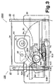
- Fig. 1 is a schematic top view of a disk playback device incorporating a disk transfer mechanism in accord with the present invention. The figure shows the disk transfer device in a standby position.
- Fig. 2 is a schematic top view of the disk playback device of Fig. 1 showing the insertion of a large size disk.
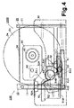
- Fig. 3 is a schematic top view of the disk playback device of Figs. 1 and 2 showing a large size disk being transferred.
- Fig. 4 is a schematic top view of the disk playback device of Figs. 1-3 showing a large size disk being brought to the playback position.
- Fig. 5 is a schematic top view of the disk playback device of Figs. 1-4 showing a large size disk during playback.
- Fig. 6 is a schematic top view of the disk playback device of Figs. 1-5 showing the insertion of a small size disk.
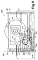
- Fig. 7 is a schematic top view of the disk playback device of Figs. 1-6 showing a small size disk being transferred.
- Fig. 8 is a schematic top view of the disk playback device of Figs. 1-7 showing a small size disk being brought to the playback position.
- Fig. 9 is a schematic top view of the disk playback device of Figs. 1-8 showing a small size disk during playback.
- Fig. 10 is an enlarged top view showing the details of the opening and closing mechanism and the bias means.
- a disk transfer device 100 includes a driven disk guide 10 on the left side of the device and a fixed disk guide 20 on the right side of the device.
- a driven disk guide 10 has a guide groove 10A which guides the left edge of a disk in the disk transfer direction. Inside guide groove 10A, there is disposed a belt 11 which drives the left outer edge of the disk. Belt 11 is reeved between pulleys 12, 13 which are placed in front and back of driven disk guide 10. Pulley 13 is connected to a driving mechanism M1.
- a fixed disk guide 20 is equipped with a guide groove 20A which receives and guides the right disk edge.
- a friction sheet 21 is fixed inside guide groove 20A to prevent disk slippage.
- Both disk guides 10, 20 are movably carried by a loading chassis 30, whereon their movement is guided by guides 30A and 30B one of which is created by the edge of loading chassis 30.
- Disk guides 10, 20 are guided in parallel movement between an initial position ( Figure 1) in which the spacing between driven belt 11 and friction sheet 21 is narrower than the diameter (80 mm) of small size disk D2 and a receiving position ( Figure 3) in which the distance between driven belt 11 and friction sheet 21 can be expanded to a value wider than the diameter (120 mm) of large size disk D1.
- Both disk guides 10, 20 are connected by a pinion gear 33 which is supported by pin 31A on loading chassis 30.
- Disk guides 10, 20 are urged together by a weak force from a spring 34. Because the resistance to disk insertion is determined by the spring force of spring 34, this force is set as weak as possible.
- Disk guides 10, 20 are moved between the initial position and the receiving position as described above by a closing and opening mechanism 50 which comprises a loading plate 51, a loading cam 52, a loading gear 53, an idle gear 54, and a driving mechanism M2 (see Figure 10).
- Loading plate 51 is guided by three pins 31C on loading chassis 30.
- Loading plate 51 is driven, by driving mechanism M2, between three positions: the standby position as shown in Figure 1 and Figure 10, the loading position as shown in Figure 3, and the playback position as shown in Figure 5.
- Loading plate 51 has a cam groove 51A.
- the angle of loading cam 52 is controlled by the position of loading plate 51.
- Loading cam 52 is supported by pin 31B on loading chassis 30.
- Pin 52A follows cam groove 51A.
- Loading gear 53 has a projection 53A which may abut idle gear 54.
- Idle gear 54 is supported by pin 31D.
- disk transfer device 100 includes a bias means 40 which can increase the disk gripping force of disk guides 10, 20 (see Figure 10).
- Bias means 40 comprises an additional spring (a coil spring 42) and a control means (a bias arm 41 and loading plate 51) which controls whether or not an additional force force is applied to disk guides 10, 20 by this spring.
- Bias arm 41 is rotatably supported on loading chassis 30 by a pin 31C. Bias arm 41 is urged in the clockwise direction by spring 42.
- a pin 41A On the tip of bias arm 41, a pin 41A abuts side 51B of loading plate 51.
- a cam surface 41B, on bias arm 41 is capable of engagement with either of pins 54B, 54C on the upper surface of idle gear 54.
- bias arm 41 When loading plate 51 is in the standby position ( Figure 1) or the playback position ( Figure 5), bias arm 41 abuts surface 51B of loading plate 51, and its clockwise rotation is prevented. As a result, cam surface 41B is outside of the transfer pathway of pins 54B, 54C. The force of spring 42 is not applied to idle gear 54 or, ultimately, to disk guides 10, 20.
- An optical mechanism 60 comprising a turntable 61 and an optical head 62, is moved beneath the disk which has been brought to the playback position.
- Optical mechanism 60 is driven by a driving mechanism M3 for movement in the vertical direction.
- Optical mechanism 60 moves between an elevated or disk-playing position and a retracted position where it is retracted below the disk.
- Above turntable 61 there is disposed a convenient clamping device (not shown) which is also capable of vertical movement. A disk mounted on turntable 61 is clamped and held in place by this device.
- disk transfer device 100 While in the standby mode, i.e when it is capable of accepting a disk, disk guides 10, 20 are retained in an initial position by the spring force of spring 34. In the initial position, the separation of disk guides 10, 20 is narrower than the diameter of a small-size disk.
- Loading plate 50 is in a standby position. As a result, pin 52A of loading cam 52 is positioned inside horizontal area 511 of cam groove 51A. Projection 53A of loading gear 53 is spaced slightly apart from the surface of idle gear 54. Pin 41A of bias arm 41 is constrained by surface 51B of loading plate 51. Cam surface 41B is retracted outside of the movement pathway of pins 54B, 54C of idle gear 54.
- Alter disk D1 is transferred to the playback position ( Figure 4), driving of belt 11 is terminated.
- Turntable 60 and optical head 61 are raised.
- the gripping device (not shown) is lowered to the upper surface of disk D, clamping it to the top of turntable 60.
- loading plate 51 is moved to the right and brought to the playback position ( Figure 5). Movement of pin 41 A of bias arm 41 is thus prevented by the surface 51B.
- Cam surface 41B is outside of the movement path of pin 54B, 54C of idle gear 54.
- the spring force of spring 42 which was applied to disk guides 10, 20 disappears.
- pin 52A of loading cam 52 enters horizontal area 512 of cam groove 51A.
- Loading gear 53 rotates in the counter-clockwise direction, causing idle gear 54 to rotate in the same direction. As a result, pinion gear 33 rotates in the clockwise direction.
- Disk guides 10, 20 spread apart to the receiving position. Belt 11 and friction sheet 21 separate from the outer edge of the disk. Disk D1 is rotated at a set linear speed to read the recorded information of the disk by optical head 61.
- disk transfer device 100 from disk insertion to playback, were explained above.
- the operation from playback of the disk to ejection of the disk from the device is simply the operation described above conducted in reverse. As a result, the description thereof will be abbreviated.
- Figures 6-9 illustrate the actions from insertion of a small size disk D2 until it is played back. These figures correspond to Figures 2-5 described above.
- idle gear 54 is only slightly rotated at the time of disk transfer.
- cam surface 41B of bias arm 41 pushes pin 54C of idle gear 54.
- the disk gripping force is increased.
- the remaining operation is the same as that described above, whereby no further description is necessary.
- spring 34 is placed between disk guides 10, 20.
- both disk guides are connected by pinion gear 33, it is possible to place spring 34 between one disk guide and loading chassis 30. It is also possible to urge idle gear 54 in the clockwise direction.
- spring 34 which draws together disk guides 10, 20 can be stretched further during disk transfer, whereby the disk gripping force is increased.
- spring 34 can be placed between either of disk guides 10, 20 and a moveable control member. During disk transfer, spring 34 is stretched by the control member, and the disk gripping force is thereby increased.
- both the left and right outer edges of the disk can be driven so that the disk is transferred without rotation.
- the present invention can be applied to various disk transfer devices. While it has been described with reference to a device adapted to transfer both large size and small size disks, it can also be applied to disk transfer devices which transfer only one or the other size disk.
- disk gripping power is increased during disk transfer. Even if the device is used in a vertical orientation or is subject to external vibrations, there is positive, reliable transfer of the disk. Further the insertion resistance is minimized and a smooth disk insertion is achieved.
Landscapes
- Feeding And Guiding Record Carriers (AREA)
Applications Claiming Priority (3)
| Application Number | Priority Date | Filing Date | Title |
|---|---|---|---|
| JP131675/97 | 1997-05-06 | ||
| JP9131675A JPH10308049A (ja) | 1997-05-06 | 1997-05-06 | ディスク移送装置 |
| JP13167597 | 1997-05-06 |
Publications (3)
| Publication Number | Publication Date |
|---|---|
| EP0877368A2 true EP0877368A2 (de) | 1998-11-11 |
| EP0877368A3 EP0877368A3 (de) | 1999-11-03 |
| EP0877368B1 EP0877368B1 (de) | 2002-07-17 |
Family
ID=15063605
Family Applications (1)
| Application Number | Title | Priority Date | Filing Date |
|---|---|---|---|
| EP98107904A Expired - Lifetime EP0877368B1 (de) | 1997-05-06 | 1998-04-30 | Plattenübertragungsvorrichtung |
Country Status (5)
| Country | Link |
|---|---|
| US (1) | US6097687A (de) |
| EP (1) | EP0877368B1 (de) |
| JP (1) | JPH10308049A (de) |
| CN (1) | CN1202698A (de) |
| DE (1) | DE69806541T2 (de) |
Families Citing this family (1)
| Publication number | Priority date | Publication date | Assignee | Title |
|---|---|---|---|---|
| WO2008105037A1 (ja) * | 2007-02-23 | 2008-09-04 | Pioneer Corporation | 情報処理装置 |
Family Cites Families (10)
| Publication number | Priority date | Publication date | Assignee | Title |
|---|---|---|---|---|
| CA1204859A (en) * | 1982-12-12 | 1986-05-20 | Nobuyuki Hara | Loading apparatus for a disc |
| BE901937A (fr) * | 1985-03-14 | 1985-07-01 | Staar Sa | Dispositif d'insertion et d'ejection automatique de supports d'informations. |
| JPH027263A (ja) * | 1988-06-25 | 1990-01-11 | Suzuki Motor Co Ltd | Cdプレーヤのローディング装置 |
| JPH0624033Y2 (ja) * | 1988-09-05 | 1994-06-22 | パイオニア株式会社 | フロントローディングディスクプレーヤ |
| US5136570A (en) * | 1989-09-14 | 1992-08-04 | Clarion Co., Ltd. | Disc ejecting structure with plurality of disk position sensors |
| US5255255A (en) * | 1990-11-27 | 1993-10-19 | Matsushita Electric Industrial, Co., Ltd. | Disk loading device |
| US5561658A (en) * | 1994-02-06 | 1996-10-01 | Nakamichi Corporation | Friction drive for a disc player |
| DE69523714T2 (de) * | 1994-08-26 | 2002-07-25 | Nakamichi Corp., Kodaira | Plattenwiedergabevorrichtung |
| JPH08241552A (ja) * | 1995-03-05 | 1996-09-17 | Nakamichi Corp | ディスク移送装置 |
| JPH08287574A (ja) * | 1995-04-13 | 1996-11-01 | Nakamichi Corp | ディスク移送装置 |
-
1997
- 1997-05-06 JP JP9131675A patent/JPH10308049A/ja active Pending
-
1998
- 1998-04-24 US US09/066,250 patent/US6097687A/en not_active Expired - Fee Related
- 1998-04-30 EP EP98107904A patent/EP0877368B1/de not_active Expired - Lifetime
- 1998-04-30 DE DE69806541T patent/DE69806541T2/de not_active Expired - Fee Related
- 1998-05-04 CN CN98107905A patent/CN1202698A/zh active Pending
Also Published As
| Publication number | Publication date |
|---|---|
| DE69806541D1 (de) | 2002-08-22 |
| DE69806541T2 (de) | 2003-04-10 |
| US6097687A (en) | 2000-08-01 |
| CN1202698A (zh) | 1998-12-23 |
| EP0877368B1 (de) | 2002-07-17 |
| EP0877368A3 (de) | 1999-11-03 |
| JPH10308049A (ja) | 1998-11-17 |
Similar Documents
| Publication | Publication Date | Title |
|---|---|---|
| JP2002074800A (ja) | ディスクローディング装置 | |
| JPH11259943A (ja) | ディスク移送装置 | |
| US6097687A (en) | Disk transfer device | |
| EP1087390B1 (de) | Platteneinheit | |
| US6587406B1 (en) | Changer type compact disk reproduction device | |
| JPH11219559A (ja) | 情報記録媒体再生装置 | |
| EP0955633B1 (de) | Plattenwechsler für einen Plattenspieler | |
| JP2828696B2 (ja) | ディスクプレーヤ | |
| US6151279A (en) | Single motor disc player with a Geneva mechanism | |
| US7290269B2 (en) | Disk recording and/or reproducing apparatus | |
| JP3970172B2 (ja) | 検知手段を有するディスク装置 | |
| US20050050561A1 (en) | Disk recording and/or reproducing device | |
| JP2000048456A (ja) | チェンジャー型ディスク再生装置 | |
| JPH11213506A (ja) | ディスク装置 | |
| US5768048A (en) | Tape cassette cover opening and closing device | |
| JP3850733B2 (ja) | ディスク装置 | |
| JPH11149688A (ja) | ディスク移送装置 | |
| JP3912991B2 (ja) | ディスクプレーヤ | |
| JP2636701B2 (ja) | ディスク装置 | |
| JP3179197B2 (ja) | ディスクプレーヤ | |
| JP2677046B2 (ja) | ディスクチェンジャー装置 | |
| JPH10289514A (ja) | ディスク移送装置 | |
| JP2000207802A (ja) | 記録媒体再生装置 | |
| JPH11213496A (ja) | ディスク装置 | |
| JP2000048458A (ja) | チェンジャー型ディスク再生装置 |
Legal Events
| Date | Code | Title | Description |
|---|---|---|---|
| PUAI | Public reference made under article 153(3) epc to a published international application that has entered the european phase |
Free format text: ORIGINAL CODE: 0009012 |
|
| AK | Designated contracting states |
Kind code of ref document: A2 Designated state(s): DE GB |
|
| AX | Request for extension of the european patent |
Free format text: AL;LT;LV;MK;RO;SI |
|
| RAP1 | Party data changed (applicant data changed or rights of an application transferred) |
Owner name: NAKAMICHI CORPORATION |
|
| PUAL | Search report despatched |
Free format text: ORIGINAL CODE: 0009013 |
|
| AK | Designated contracting states |
Kind code of ref document: A3 Designated state(s): AT BE CH CY DE DK ES FI FR GB GR IE IT LI LU MC NL PT SE |
|
| AX | Request for extension of the european patent |
Free format text: AL;LT;LV;MK;RO;SI |
|
| 17P | Request for examination filed |
Effective date: 20000427 |
|
| AKX | Designation fees paid |
Free format text: DE GB |
|
| 17Q | First examination report despatched |
Effective date: 20001222 |
|
| GRAG | Despatch of communication of intention to grant |
Free format text: ORIGINAL CODE: EPIDOS AGRA |
|
| GRAG | Despatch of communication of intention to grant |
Free format text: ORIGINAL CODE: EPIDOS AGRA |
|
| GRAH | Despatch of communication of intention to grant a patent |
Free format text: ORIGINAL CODE: EPIDOS IGRA |
|
| GRAH | Despatch of communication of intention to grant a patent |
Free format text: ORIGINAL CODE: EPIDOS IGRA |
|
| GRAA | (expected) grant |
Free format text: ORIGINAL CODE: 0009210 |
|
| AK | Designated contracting states |
Kind code of ref document: B1 Designated state(s): DE GB |
|
| REG | Reference to a national code |
Ref country code: GB Ref legal event code: FG4D |
|
| REF | Corresponds to: |
Ref document number: 69806541 Country of ref document: DE Date of ref document: 20020822 |
|
| PLBE | No opposition filed within time limit |
Free format text: ORIGINAL CODE: 0009261 |
|
| STAA | Information on the status of an ep patent application or granted ep patent |
Free format text: STATUS: NO OPPOSITION FILED WITHIN TIME LIMIT |
|
| 26N | No opposition filed |
Effective date: 20030422 |
|
| PGFP | Annual fee paid to national office [announced via postgrant information from national office to epo] |
Ref country code: DE Payment date: 20080627 Year of fee payment: 11 |
|
| PGFP | Annual fee paid to national office [announced via postgrant information from national office to epo] |
Ref country code: GB Payment date: 20080417 Year of fee payment: 11 |
|
| GBPC | Gb: european patent ceased through non-payment of renewal fee |
Effective date: 20090430 |
|
| PG25 | Lapsed in a contracting state [announced via postgrant information from national office to epo] |
Ref country code: DE Free format text: LAPSE BECAUSE OF NON-PAYMENT OF DUE FEES Effective date: 20091103 |
|
| PG25 | Lapsed in a contracting state [announced via postgrant information from national office to epo] |
Ref country code: GB Free format text: LAPSE BECAUSE OF NON-PAYMENT OF DUE FEES Effective date: 20090430 |