EP0877456A1 - Überspannungsschutz - Google Patents
Überspannungsschutz Download PDFInfo
- Publication number
- EP0877456A1 EP0877456A1 EP98107492A EP98107492A EP0877456A1 EP 0877456 A1 EP0877456 A1 EP 0877456A1 EP 98107492 A EP98107492 A EP 98107492A EP 98107492 A EP98107492 A EP 98107492A EP 0877456 A1 EP0877456 A1 EP 0877456A1
- Authority
- EP
- European Patent Office
- Prior art keywords
- contact
- base body
- surge
- spring
- web
- Prior art date
- Legal status (The legal status is an assumption and is not a legal conclusion. Google has not performed a legal analysis and makes no representation as to the accuracy of the status listed.)
- Withdrawn
Links
Images


Classifications
-
- H—ELECTRICITY
- H01—ELECTRIC ELEMENTS
- H01T—SPARK GAPS; OVERVOLTAGE ARRESTERS USING SPARK GAPS; SPARKING PLUGS; CORONA DEVICES; GENERATING IONS TO BE INTRODUCED INTO NON-ENCLOSED GASES
- H01T4/00—Overvoltage arresters using spark gaps
- H01T4/06—Mounting arrangements for a plurality of overvoltage arresters
Definitions
- the invention relates to an overvoltage protection module with the features of the preamble of Claim 1.
- an overvoltage protection module of the generic type is previously known from DE-A-2 315 838.
- the contact springs are parts of a U-shaped cross section metallic holder, being at the free ends the contact springs additional contact fingers for contacting the one embedded in the plastic body Contact strips are arranged.
- the U-shaped, the holder having contact springs required a laborious assembly on the top of the Main body held by the contact springs, with Surge arrester provided with fusible elements.
- the U-shaped holder needs a large one Cost of materials.
- the invention is based, the overvoltage protection module the task of this kind to improve.
- the invention provides that the contact springs on one on top of the Base body clampable spring comb are formed, of which at least the web holding the contact springs a spring contact for contacting an earth conductor having.
- the surge protection module according to the invention is thus with regard to the arrangement of the Surge arrester provided with fusible elements designed to be easier to install, as this can only be done by means of that can be clamped onto the top of the base body Feather comb are held on the one hand the Contact springs to hold the surge arresters and on the other hand at least one spring contact for contacting of the earth conductor. This results in in addition to a simplified assembly, a considerable one Savings in metallic material for training the contact springs. Due to the one-piece design of the Spring comb is the amount of parts needed to contact the Surge protection module with an earth conductor decreased.
- the surge protection module consists of a basic body 1 made of plastic with embedded contact strips 2, on the top of the base body 1 arranged, provided with melting elements 3 surge arresters 4 and from the surge arrester 4 and the melting elements 3 on the base body 1
- Contact springs 5 for contacting the contact strips 2 when softening a melting element 3 under a Overload.
- the contact springs 5 are on one can be clamped onto the upper side 6 of the base body 1 Spring comb 7 formed, the contact springs 5 web 8 holding at least one spring contact 9 for Contacting an earth conductor 10.
- the base body 1 made of plastic comprises a base plate 11, in which the metallic contact strips 2 are embedded, at their free ends U-shaped designed contact taps 12 are exposed.
- the Base plate 11 carries an in on the top 6 Longitudinal direction, i.e. across the contact strips 2, extending strip 13 made of plastic and on the free ends of the contact strips 2 facing away from the long side two staggered rows of circular walls 14 to form troughs 15 for receiving the Surge arrester 4 and the associated Melting elements 3.
- On the upper edge 16 of the walls 14 4 and 5 are angled contact strips 2 with contact ramps 17 free, which the free The ends of the contact springs 5 of the spring comb 7 face each other, as shown in Figs. 4 and 5.
- the bar 13 and walls 14 are with the base body 1 and the base plate 11 integrally formed from plastic.
- Spring comb 7 consists of metallic, conductive Material and comprises a continuous web 8, on one side of the contact springs 5 and on the other side lobe-shaped support elements 18 and between these the spring contacts 9 are formed. These are angled out of the plane of the web 8, L-shaped, bent up from the bridge 8 Tabs 19 formed, of which two tabs 19 are provided and one in Fig. 5 in its functional position is shown.
- the one provided with the free ends of the contact strips 2 End of the base body 1 forms the plug-in part a protective plug.
- the spring contact 9 is for contacting of the earth conductor 10 on the free ends the contact strip 2 facing the web 8 of the spring comb 7 and formed with the free ends of the contact strips 2 provided end of Base body 1 arranged.
- the free end of the base plate 11 of the base body 1 passes through one Opening 24 in a component forming the earth conductor 10 20, the tab 19 on the earth conductor 10 of the component 20 comes to the plant.
- the web 8 lies on the troughs 15 for the surge arrester 4 facing away from the outside of the strip 13 of the base body 1 as shown in FIGS. 4 and 5, wherein the support elements on one side of the web 8 18 and the two spring contacts 9 and the Tabs 19 and on the other side the angled Extend contact springs 5.
- the strip 13 made of plastic is on the troughs 15 for the surge arrester 4 opposite side with at least two Provided locking lugs 21, behind which the web 8 of the Spring comb 7 between two adjacent contact springs can be clamped, as shown in Fig. 4 Fig. 5.
- the surge protection module shown in Figures 1 to 5 forms a protective plug consisting of the base body 1 made of plastic, in which the line contacts contact strips 2 are embedded, the spring comb 7 plugged onto the base body 1 made of spring material, the surge arresters 4 with Melting elements 3, which between the individual surge arresters 4 and the respectively assigned Contact strips 2 are arranged as a contact track.
- the surge arrester 4 and Melting elements 3 are the troughs 15 in the base body 1 in high packing density in the longitudinal and transverse directions of the Basic body 1 executed in staggered rows.
- the ends of the Contact strip 2 near the surge arrester 4 designed as contact ramps 17, which the Contact lugs 22 of the contact springs 5 face each other.
- the spring comb 7 consists of the one side the web 8 arranged shorter and longer Contact springs 5 for contacting the electrodes of the Surge arrester 4 and out on the other Support elements 18 arranged on the side of the web 8 on the one hand and the spring contacts 9 in the form of Tabs 19 for ground contact.
- the contact springs 5 for contacting the surge arrester 4 and the Spring contacts 9 for contacting the earth conductor 10 are in a single component, namely the spring comb 7, trained.
- To contact the collective earth forming earth conductor 10 are no further resilient Contact elements necessary.
- the earth conductor 10 makes contact thus directly with an L-shaped design Tab 19 the common earth, creating the interface to the distributor is formed.
- the spring comb 7 is in an open design and can simple and with a short installation path on the top 6 of the base body 1 made of plastic.
- the support elements 18 serve as a support.
- Of the Spring comb 7 is against the spring force of the contact springs 5 under the correspondingly designed locking lugs 21 of the bar 13 pressed and thus on the base body 1 made of plastic.
- the spring comb 7 is in the assembled state good on the base body 1 and thus on the surge protection module forming a protective plug accessible and can be without assemble and disassemble special aids. This makes it quick and easy to replace used protective components in the form of Surge arrester 4 together with fusible elements 3 especially in on-site service.
- the contact springs 5 of the spring comb 7 in the contact area with the Surge arresters 4 with dome-shaped expressions can be provided as a pivot and pivot point. These are supposed to be an upward movement of the surge arrester 4 and thus a possible opening of the Counteracting contact in the u range.
- the troughs 15 are designed with a high packing density and in addition to a lateral offset of the surge protection module also staggered in altitude. This allows independent movement of the springy Contact springs 5 in a confined space. If the rows of Troughs 15 are not staggered, the contact springs 5 for an independent movement so that the front surge arrester at The lower surge arrester does not melt the movement of the contact spring limits what a Production of the spring comb 7 would complicate.
Landscapes
- Fuses (AREA)
- Thermistors And Varistors (AREA)
- Emergency Protection Circuit Devices (AREA)
- Breakers (AREA)
Abstract
Description
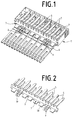
- Fig. 1
- Eine perspektivische Draufsicht auf den Überspannungsmodul,
- Fig. 2
- eine perspektivische Draufsicht auf den Federkamm,
- Fig. 3
- eine Draufsicht auf den Überspannungsschutzmodul nach Fig. 1,
- Fig. 4
- einen Schnitt durch den Überspannungsschutzmodul gemäß Linie A-A in Fig. 3,
- Fig. 5
- einen Schnitt durch den Überspannungs schutzmodul gemäß Linie B-B in Fig. 3,
- Fig. 6
- eine perspektivische Draufsicht auf die abgewandelte Ausführungsform des Überspannungsschutzmoduls und
- Fig. 7
- ein vergrößertes Detail der abgewandelten Ausführungsform des Federkontaktes zur Kontaktierung des Erdkontaktes gemäß Fig.6.
- 01
- Grundkörper
- 02
- Kontaktstreifen
- 03
- Schmelzelement
- 04
- Überspannungsableiter
- 05
- Kontaktfeder
- 06
- Oberseite
- 07
- Federkamm
- 08
- Steg
- 09
- Federkontakt
- 10
- Erdleiter
- 11
- Grundplatte
- 12
- Kontaktabgriff
- 13
- Leiste
- 14
- Wand
- 15
- Mulde
- 16
- Oberkante
- 17
- Kontaktrampe
- 18
- Abstützelement
- 19
- Lasche
- 20
- Bauteil
- 21
- Rastnase
- 22
- Kontaktnase
- 23
- Lasche
- 24
- Öffnung
Claims (7)
- Überspannungsschutzmodul aus einem Grundkörper aus Kunststoff mit eingebetteten Kontaktstreifen, aus auf der Oberseite des Grundkörpers angeordneten, mit Schmelzelementen versehenen Überspannungsableitern und aus die Überspannungsableiter und die Schmelzelemente am Grundkörper haltenden Kontaktfedern zur Kontaktierung der Kontaktstreifen beim Erweichen eines Schmelzelementes unter einer Überspannung,
dadurch gekennzeichnet,
daß die Kontaktfedern (5) an einem auf die Oberseite (6) des Grundkörpers (1) aufklemmbaren Federkamm (7) gebildet sind, dessen die Kontaktfedern (5) haltender Steg (8) mindestens einen Federkontakt (9) zum Kontaktieren eines Erdleiters (10) aufweist. - Überspannungsschutzmodul nach Anspruch 1, dadurch gekennzeichnet, daß die Oberseite (6) des Grundkörpers (1) mit kreisbogenförmigen Wänden (14) zur Bildung von Mulden (15) für die Aufnahme der Überspannungsableiter (4) und die Kontaktstreifen (2) mit abgewinkelten, auf der Oberkante (16) der Wände (14) gebildeten Kontaktrampen (17) versehen sind, denen die freien Enden der Kontaktfedern (5) des Federkammes (7) gegenüberstehen.
- Überspannungsschutzmodul nach Anspruch 2, dadurch gekennzeichnet, daß auf der Oberseite 86) des Grundkörpers (1) zwischen den Mulden (15) für die Überspannungsableiter (4) und den freien Enden der Kontaktstreifen (2) eine Leiste (13) aus Kunststoff ausgebildet ist, die auf der den Mulden (15) für die Überspannungsableiter (4) abgewandten Seite mit Rastnasen (21) versehen ist, hinter denen der Steg (8) des Federkammes (7) einklemmbar ist.
- Überspannungsschutzmodul nach Anspruch 3, wobei die Überspannungsableiter in mindestens zwei Reihen und versetzt zueinander auf der Oberseite des Grundkörpers angeordnet sind, dadurch gekennzeichnet, daß die Kontaktfedern (5) für die von der Leiste weiter entfernte Reihe von Überspannungsableitern (4) länger sind als die Kontaktfedern (5) für die der Leiste (13) benachbarte Reihe von Überspannungsableitern (4).
- Überspannungsschutzmodul nach Anspruch 1, dadurch gekennzeichnet, daß das mit den freien Enden der Kontaktstreifen (2) versehene Ende des Grundkörpers (1) den Steckteil eines Schutzsteckers bildet und der mindestens einen Federkontakt (9) zur Kontaktierung des Erdleiters (10) auf der den freien Enden der Kontaktstreifen (2) zugewandten Seite des Steges (8) des Federkammes (7) ausgebildet und an dem mit den freien Enden der Kontaktstreifen (5) versehene Ende des Grundkörpers (1) angeordnet ist.
- Überspannungsschutzmodul nach Anspruch 5, dadurch gekennzeichnet, daß der Federkontakt (9) als aus der Ebene des Steges (8) L-förmig hochgebogene, vom Steg (8) freigeschnittene Lasche (19) gebildet ist.
- Überspannungsschutzmodul nach Anspruch 5, dadurch gekennzeichnet, daß der Federkontakt (9) als aus der Ebene des Steges (8) an dessen freiem Ende U-förmig umgebogene, vom Steg (8) freigeschnittene Lasche (23) gebildet ist.
Applications Claiming Priority (2)
| Application Number | Priority Date | Filing Date | Title |
|---|---|---|---|
| DE19721047A DE19721047A1 (de) | 1997-05-09 | 1997-05-09 | Überspannungsschutzmodul |
| DE19721047 | 1997-05-09 |
Publications (1)
| Publication Number | Publication Date |
|---|---|
| EP0877456A1 true EP0877456A1 (de) | 1998-11-11 |
Family
ID=7829970
Family Applications (1)
| Application Number | Title | Priority Date | Filing Date |
|---|---|---|---|
| EP98107492A Withdrawn EP0877456A1 (de) | 1997-05-09 | 1998-04-24 | Überspannungsschutz |
Country Status (22)
| Country | Link |
|---|---|
| US (1) | US5923238A (de) |
| EP (1) | EP0877456A1 (de) |
| JP (1) | JPH1125830A (de) |
| KR (1) | KR19980086896A (de) |
| CN (1) | CN1199918A (de) |
| AR (1) | AR015640A1 (de) |
| AU (1) | AU737744B2 (de) |
| BG (1) | BG63323B1 (de) |
| BR (1) | BR9801184A (de) |
| CA (1) | CA2236701A1 (de) |
| CO (1) | CO4650246A1 (de) |
| CZ (1) | CZ143498A3 (de) |
| DE (1) | DE19721047A1 (de) |
| EG (1) | EG21109A (de) |
| ID (1) | ID20817A (de) |
| IL (1) | IL124254A (de) |
| NO (1) | NO982065L (de) |
| PL (1) | PL326181A1 (de) |
| TR (1) | TR199800831A2 (de) |
| TW (1) | TW369661B (de) |
| YU (1) | YU20398A (de) |
| ZA (1) | ZA983898B (de) |
Families Citing this family (21)
| Publication number | Priority date | Publication date | Assignee | Title |
|---|---|---|---|---|
| US6198615B1 (en) * | 1998-06-12 | 2001-03-06 | Avaya Inc. | Voltage unit bus clip |
| DE10007173B4 (de) * | 2000-02-17 | 2005-03-03 | CCS Technology, Inc., Wilmington | Steckbare Baugruppe zum Sichern von elektrischen Leitungen in einem Verteiler einer Telekommunikationsanlage |
| US6636409B2 (en) * | 2001-04-16 | 2003-10-21 | Eaton Corporation | Surge protection device including a thermal fuse spring, a fuse trace and a voltage clamping device |
| US6556411B1 (en) * | 2002-04-02 | 2003-04-29 | Marconi Communications, Inc. | Purge protection cartridge with three-way attachment clip |
| US6814631B2 (en) * | 2002-04-02 | 2004-11-09 | Marconi Intellectual Property (Ringfence) Inc. | Electrical terminal for surge protection cartridge |
| DE102004061681B4 (de) | 2004-12-22 | 2006-10-26 | Adc Gmbh | Kabelsteckverbinder für Leiterplatten |
| WO2007017736A1 (en) * | 2005-08-05 | 2007-02-15 | Kiwa Spol. S R.O. | Overvoltage protection with status signalling |
| DE102007006693A1 (de) * | 2007-02-12 | 2008-08-21 | Adc Gmbh | Überspannunsschutzmagazin |
| US8064182B2 (en) * | 2007-02-28 | 2011-11-22 | Adc Telecommunications, Inc. | Overvoltage protection plug |
| USD591691S1 (en) | 2007-02-28 | 2009-05-05 | Adc Telecommunications, Inc. | Overvoltage protection plug |
| DE102007026102B3 (de) * | 2007-06-05 | 2008-11-13 | Adc Gmbh | Steckverbinder für Leiterplatten |
| DE102007026095A1 (de) * | 2007-06-05 | 2008-12-11 | Adc Gmbh | Erdkamm, insbesondere für einen Steckverbinder für Leiterplatten |
| DE102007026094B4 (de) * | 2007-06-05 | 2023-05-11 | Tyco Electronics Services Gmbh | Kontaktelement für einen Steckverbinder für Leiterplatten |
| DE102007026096A1 (de) * | 2007-06-05 | 2008-12-11 | Adc Gmbh | Aderanschlussmodul |
| DE102007026097B4 (de) * | 2007-06-05 | 2023-05-11 | Tyco Electronics Services Gmbh | Steckverbinder für Leiterplatten |
| DE102007042991B4 (de) * | 2007-06-11 | 2009-09-17 | Dehn + Söhne Gmbh + Co. Kg | Überspannungsschutzgerät mit im thermischen Überlastfall aktivierter mechanischer Abtrennvorrichtung |
| DE102007050590B4 (de) * | 2007-10-23 | 2017-04-13 | Tyco Electronics Services Gmbh | Verteileranschlussmodul |
| US7946863B2 (en) * | 2008-04-25 | 2011-05-24 | Adc Telecommunications, Inc. | Circuit protection block |
| US8411404B2 (en) * | 2008-05-27 | 2013-04-02 | Adc Telecommunications, Inc. | Overvoltage protection plug |
| USD620896S1 (en) | 2008-05-27 | 2010-08-03 | Adc Telecommunications, Inc. | Overvoltage protection plug |
| DE102009010929A1 (de) * | 2009-02-27 | 2010-09-09 | Adc Gmbh | Überspannungsschutzmagazin oder -stecker und Verfahren zur Herstellung eines Überspannungsschutzmagazins oder -steckers |
Citations (2)
| Publication number | Priority date | Publication date | Assignee | Title |
|---|---|---|---|---|
| DE2315838A1 (de) * | 1973-03-29 | 1974-10-03 | Siemens Ag | Sicherungsleiste mit einer anzahl von elektrischen sicherungen |
| US4504883A (en) * | 1982-05-20 | 1985-03-12 | Kabushiki Kaisha Sankosha | Arrester holder apparatus for distributor of communication apparatus |
Family Cites Families (7)
| Publication number | Priority date | Publication date | Assignee | Title |
|---|---|---|---|---|
| US2546824A (en) * | 1947-12-11 | 1951-03-27 | Bell Telephone Labor Inc | Electrical protective apparatus |
| DE2428266C3 (de) * | 1974-06-12 | 1983-02-10 | Krone Gmbh, 1000 Berlin | Steckkartenartig ausgebildete Isolierstoff-Einschubleiste mit Überspannungsableitern und Verfahren zu ihrer Herstellung |
| DE2555794C2 (de) * | 1974-06-12 | 1984-03-08 | Krone Gmbh, 1000 Berlin | Isolierstoff-Einschubleiste mit Überspannungsableitern |
| DE2508845C3 (de) * | 1975-02-28 | 1980-10-02 | Siemens Ag, 1000 Berlin Und 8000 Muenchen | Sicherungsleiste |
| FR2485286A1 (fr) * | 1980-05-06 | 1981-12-24 | Roudeau Maurice | Module de raccordement a coupure et protection pour circuit electrique unique ou multiple |
| EP0258629A3 (de) * | 1986-08-25 | 1990-01-31 | Siemens Aktiengesellschaft | Baugruppe zum Sichern von elektrischen Leitungen in Telekommunikationsanlagen |
| DE4437122C2 (de) * | 1994-10-01 | 1996-07-18 | Krone Ag | Überspannungsschutzstecker |
-
1997
- 1997-05-09 DE DE19721047A patent/DE19721047A1/de not_active Withdrawn
-
1998
- 1998-04-24 EP EP98107492A patent/EP0877456A1/de not_active Withdrawn
- 1998-04-28 IL IL12425498A patent/IL124254A/en not_active IP Right Cessation
- 1998-04-30 BG BG102421A patent/BG63323B1/bg unknown
- 1998-05-01 AU AU63744/98A patent/AU737744B2/en not_active Ceased
- 1998-05-04 CO CO98024288A patent/CO4650246A1/es unknown
- 1998-05-05 CA CA002236701A patent/CA2236701A1/en not_active Abandoned
- 1998-05-06 EG EG49198A patent/EG21109A/xx active
- 1998-05-06 PL PL98326181A patent/PL326181A1/xx unknown
- 1998-05-06 NO NO982065A patent/NO982065L/no not_active Application Discontinuation
- 1998-05-07 AR ARP980102117A patent/AR015640A1/es unknown
- 1998-05-07 CZ CZ981434A patent/CZ143498A3/cs unknown
- 1998-05-07 US US09/074,615 patent/US5923238A/en not_active Expired - Fee Related
- 1998-05-08 TR TR1998/00831A patent/TR199800831A2/xx unknown
- 1998-05-08 BR BR9801184-7A patent/BR9801184A/pt not_active IP Right Cessation
- 1998-05-08 JP JP10126035A patent/JPH1125830A/ja active Pending
- 1998-05-08 ID IDP980685A patent/ID20817A/id unknown
- 1998-05-08 YU YU20398A patent/YU20398A/sh unknown
- 1998-05-08 TW TW087107159A patent/TW369661B/zh active
- 1998-05-08 ZA ZA9803898A patent/ZA983898B/xx unknown
- 1998-05-09 CN CN98108768A patent/CN1199918A/zh active Pending
- 1998-05-09 KR KR1019980016603A patent/KR19980086896A/ko not_active Withdrawn
Patent Citations (2)
| Publication number | Priority date | Publication date | Assignee | Title |
|---|---|---|---|---|
| DE2315838A1 (de) * | 1973-03-29 | 1974-10-03 | Siemens Ag | Sicherungsleiste mit einer anzahl von elektrischen sicherungen |
| US4504883A (en) * | 1982-05-20 | 1985-03-12 | Kabushiki Kaisha Sankosha | Arrester holder apparatus for distributor of communication apparatus |
Also Published As
| Publication number | Publication date |
|---|---|
| YU20398A (sh) | 2002-09-19 |
| AR015640A1 (es) | 2001-05-16 |
| BR9801184A (pt) | 1999-11-09 |
| TR199800831A3 (tr) | 1999-06-21 |
| TW369661B (en) | 1999-09-11 |
| IL124254A (en) | 2001-06-14 |
| JPH1125830A (ja) | 1999-01-29 |
| NO982065D0 (no) | 1998-05-06 |
| CO4650246A1 (es) | 1998-09-03 |
| AU737744B2 (en) | 2001-08-30 |
| AU6374498A (en) | 1998-11-12 |
| EG21109A (en) | 2000-11-29 |
| PL326181A1 (en) | 1998-11-23 |
| ID20817A (id) | 1999-03-11 |
| CN1199918A (zh) | 1998-11-25 |
| DE19721047A1 (de) | 1998-11-12 |
| KR19980086896A (ko) | 1998-12-05 |
| CA2236701A1 (en) | 1998-11-09 |
| BG102421A (en) | 1998-11-30 |
| ZA983898B (en) | 1999-11-08 |
| NO982065L (no) | 1998-11-10 |
| BG63323B1 (bg) | 2001-09-28 |
| US5923238A (en) | 1999-07-13 |
| TR199800831A2 (xx) | 1999-06-21 |
| CZ143498A3 (cs) | 1998-12-16 |
Similar Documents
| Publication | Publication Date | Title |
|---|---|---|
| DE19721047A1 (de) | Überspannungsschutzmodul | |
| DE4223540C2 (de) | Querverbinder für Reihenklemmen | |
| EP0312729B1 (de) | Thermoschutzvorrichtung für in Überspannungsableitermagazine der Fernmeldetechnik eingebaute Überspannungsableiter | |
| DE19521913C2 (de) | Doppelsicherheitsthermostat | |
| EP0706194A1 (de) | Schutzstecker | |
| EP0436881B1 (de) | Überspannungsableiter | |
| DE4411187A1 (de) | Stromleitungs-Verbinder | |
| DE10355195A1 (de) | Leiteranschluss | |
| DE4216422C2 (de) | Verteilerelement für die elektrische Nachrichtentechnik | |
| DE19711128C1 (de) | Verteilerleiste für die Telekommunikations- und Datentechnik | |
| DE2315838C3 (de) | Sicherungsleiste mit einer Mehrzahl elektrischer Sicherungen | |
| DE102006031584B4 (de) | Miniaturisierter elektrischer Schalter | |
| EP0880201A2 (de) | Sicherungsstecker | |
| EP0267145B1 (de) | Schneidklemm-Anschlusselement für elektrische Leiter | |
| EP0405337B1 (de) | Schutzstecker für eine Verteilerleiste in einer Telekommunikationsanlage | |
| DE4225484C1 (de) | Schutzstecker für Anschluß- und Trennleisten der Telekommunikations- und Datentechnik | |
| DE19745803C1 (de) | Kontaktfeder für einen Mikroschalter mit Überhub | |
| DE3628423A1 (de) | Kontaktanordnung fuer elektrische schaltgeraete | |
| DE19816907A1 (de) | Schutzstecker für eine Einrichtung der Telekommunikationstechnik | |
| DE19811476C1 (de) | Kabelklemme | |
| DE3921225C1 (en) | Protective device for distributor in telecommunications system - has over-voltage arrester with wire-type terminal pins, e.g. for telephone exchange | |
| EP3413400B1 (de) | Querverbinderkamm | |
| EP1575076B1 (de) | Sicherungsträger für Flachsicherungen | |
| EP0258628B1 (de) | Baugruppe zum Sichern von elektrischen Leitungen in Verteilern von Telekommunikationsanlagen | |
| DE102006006316B3 (de) | Elektrischer Buchsenkontakt |
Legal Events
| Date | Code | Title | Description |
|---|---|---|---|
| PUAI | Public reference made under article 153(3) epc to a published international application that has entered the european phase |
Free format text: ORIGINAL CODE: 0009012 |
|
| 17P | Request for examination filed |
Effective date: 19980826 |
|
| AK | Designated contracting states |
Kind code of ref document: A1 Designated state(s): AT BE CH DE DK ES FI FR GB GR IE IT LI NL PT SE |
|
| AX | Request for extension of the european patent |
Free format text: AL;LT;LV;MK;RO PAYMENT 980826;SI |
|
| AKX | Designation fees paid |
Free format text: AT BE CH DE DK ES FI FR GB GR IE IT LI NL PT SE |
|
| AXX | Extension fees paid |
Free format text: RO PAYMENT 19980826 |
|
| RAP1 | Party data changed (applicant data changed or rights of an application transferred) |
Owner name: KRONE GMBH |
|
| 17Q | First examination report despatched |
Effective date: 20010417 |
|
| STAA | Information on the status of an ep patent application or granted ep patent |
Free format text: STATUS: THE APPLICATION HAS BEEN WITHDRAWN |
|
| 18W | Application withdrawn |
Withdrawal date: 20011205 |