EP0877489A2 - Convertisseur résolveur-numérique direct - Google Patents
Convertisseur résolveur-numérique direct Download PDFInfo
- Publication number
- EP0877489A2 EP0877489A2 EP98108304A EP98108304A EP0877489A2 EP 0877489 A2 EP0877489 A2 EP 0877489A2 EP 98108304 A EP98108304 A EP 98108304A EP 98108304 A EP98108304 A EP 98108304A EP 0877489 A2 EP0877489 A2 EP 0877489A2
- Authority
- EP
- European Patent Office
- Prior art keywords
- values
- sin
- resolver
- cos
- octant
- Prior art date
- Legal status (The legal status is an assumption and is not a legal conclusion. Google has not performed a legal analysis and makes no representation as to the accuracy of the status listed.)
- Withdrawn
Links
- 238000000034 method Methods 0.000 claims description 5
- 238000004804 winding Methods 0.000 description 9
- 238000010586 diagram Methods 0.000 description 2
- 238000005070 sampling Methods 0.000 description 2
- 230000036039 immunity Effects 0.000 description 1
- 238000009434 installation Methods 0.000 description 1
Images



Classifications
-
- H—ELECTRICITY
- H03—ELECTRONIC CIRCUITRY
- H03M—CODING; DECODING; CODE CONVERSION IN GENERAL
- H03M1/00—Analogue/digital conversion; Digital/analogue conversion
- H03M1/12—Analogue/digital converters
- H03M1/64—Analogue/digital converters with intermediate conversion to phase of sinusoidal or similar periodical signals
- H03M1/645—Analogue/digital converters with intermediate conversion to phase of sinusoidal or similar periodical signals for position encoding, e.g. using resolvers or synchros
Definitions
- the resolver includes a primary winding energized from a carrier frequency source and includes a pair of relatively rotatable secondary windings positioned in a quadrature relationship.
- the secondary windings provide signals at the carrier frequency with an amplitude envelope corresponding to sine ⁇ and cosine ⁇ , respectively, where ⁇ is an angular position of the resolver shaft.
- the signals are then demodulated to remove carrier and recover the amplitude envelope.
- the sine ⁇ and cosine ⁇ signal values are then processed to determine the angle ⁇ which is the shaft position.
- Resolver to digital processors are available which convert analog signals to digital values representing the angular shaft position ⁇ .
- Such processors usually provide a digital shaft angle representation and an analog velocity indication.
- disadvantages of the prior processes are relatively poor digital resolution (particularly at high speeds) and limited tracking error tolerance.
- the phase relationship between the modulating source and the modulated feedback to provide the sine and cosine values is critical and often requires special cables. Also, such systems have limited noise rejection.
- An object of the present invention is to provide a low cost resolver to digital converter which can be constructed using readily available components.
- Another object is to provide a resolver to digital converter which provides both position and velocity data in a high-resolution digital form.
- the sine ⁇ and co sine ⁇ signals provided by the resolver are demodulated to remove the carrier and then converted to digital values which are stored in memory associated with a conventional microprocessor.
- the sine and cosine values are compared to determine the octant for the angle ⁇ .
- the octant is determined on the basis of the polarity of the sine and cosine signals and by determining whether or not the sine value has a larger absolute value than the cosine value.
- the octant determination provides the three most significant bits indicating the shaft position.
- the sine and cosine values are further processed according to the octant position.
- the smaller absolute value is divided by the larger value to derive a tangent ⁇ value in the range of 0 to 1.0.
- the tangent ⁇ value is close to linear with a deviation of less than 7% maximum and, therefore, provides relatively uniform resolution throughout the range.
- the tangent ⁇ values are then converted to linear values using a look-up table.
- the corrected tangent values are then inverted for odd octants and thereafter added to the octant values to provide the shaft angle position.
- the velocity can be determined digitally as the difference in value between two successive angle position samples.
- Figure 1 is a block diagram of the resolver and associated units for processing the resolver signal and supplying same to a microprocessor.
- Figure 2 is a functional diagram illustrating the computer processing of the resolver output signals.
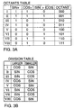
- Figure 3A is a table used to determine the octants and Figure 3B is a table used to determine tangent values.
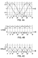
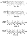
- Figures 4A through 4H are illustrations of computer processing using sine and cosine signals from the resolver to determine the shaft angle ⁇ .
- the hardware portion of the system according to the invention is illustrated in Figure 1 including resolver 10 and microcomputer 12 .
- the resolver produces the signals sine ⁇ and cosine ⁇ where ⁇ is the resolver shaft angle position.
- the signals from the resolver are processed in the microcomputer using software functionally organized as shown in Figure 2 to determine shaft angle ⁇ as well as shaft velocity.
- Resolver 10 includes a rotational primary winding 16 and a pair of stationary secondary windings 14 and 15 .
- Windings 14 and 15 have a quadrature relationship to produce sine ⁇ and cosine ⁇ signals, respectively.
- the primary winding is excited from a carrier frequence source 17 which is typically in the range between 1 Khz and 20 Khz. In most cases, the higher frequencies are preferred.
- the amplitude of the signals induced in secondary windings 14 and 15 are proportional to sine ⁇ and cosine ⁇ , respectively.
- the modulated signal sine ⁇ passes through a voltage buffer 20 (typically in the form of a voltage follower) and then through a differential amplifier 21 connected to the common signal ground for the system.
- the buffer and differential amplifier combination connected to the common signal ground provides good noise rejection.
- the signal then passes through a phase demodulator 22 which removes the carrier leaving the envelope which is the sine ⁇ .
- the signal from the phase demodulator passes through a filter 23 which rejects the carrier frequency and passes the signal on to analog-to-digital converter 24 .
- the signal emerging from A/D converter is designated SIN and is a 12-bit digital indication corresponding to the analog value sine ⁇ .
- cosine ⁇ signal originating from resolver winding 15 is processed through units 30-34 to provide the digital value of cosine ⁇ which is referred to as COS.
- the COS signal is supplied to microcomputer 12 .
- sampling of the analog signals in analog-to-digital converters 24-34 is typically accomplished at the rate of at least one sample per millisecond.
- the SIN and COS values are stored at designated memory locations in microcomputer 12 .
- the processing of the SIN and COS values to determine the resolver angle ⁇ includes (1) determining the octant for the angle ⁇ , (2) determining the tangent value, (3) correcting the tangent value to obtain a linar value for the angle ⁇ , and then (4) determining the angle ⁇ by combining the octant and linear values.
- the octant is determined by the comparison of the polarities of the SIN and COS values and their relative magnitudes. In determining the tangent values it is necessary to avoid calculations that would cause the tangent value to go to infinity. This is achieved by always dividing the smaller of the absolute values of SIN and COS by the larger value.
- the tangent values range from zero to one.
- the tangent values are close to the linear values for the angle ⁇ and are corrected using a look-up table.
- the final value for the angle ⁇ is then determined by using the octant to provide the three most significant bits and the corrected tangent value for the lesser bit.
- the SIN and COS values are equal and can be placed in either octant I or octant II. In cases where the values are equal, it makes no difference which octant is used so long as the remainder of the processing is consistent with the octant determination.
- the analog sine ⁇ and cosine ⁇ signals pass through analog-to-digital converters 24 and 34 which provide 12-bit digital words corresponding to the SIN and COS values, respectively.
- the SIN and COS values are compared in comparator operation 40 to determine the polarity and the relative magnitude. For example, as shown in the Octants Table in Figure 3A, if the SIN and COS values are both positive and the absolute value of the SIN value is not grater than the COS value, the resolver angle 8 is in the first octant I (000). Similarly, if the SIN and COS signals are both positive and the SIN value is greater, the resolver angle ⁇ is in the second octant II (001).
- octants are determined in similar fashion following the logic in the Octants Table. The locations of the octants relative to the SIN and COS values are shown in Figure 4A.
- the 3-bit octant identifier is stored in memory 42 (Fig. 2).
- the comparison in comparator operation 40 also determines if the absolute SIN and COS values are greater or less than 0.707. If the value is greater than 0.707, it is stored in a "larger” memory 44 , whereas if the value is less than 0.707, it is stored in a "smaller” memory 46 .
- the "larger” and “smaller” values for the different resolver angles are shown in Figures 4B and 4C, respectively.
- the "smaller” value is divided by the "larger” value in division operation 48 to obtain the TAN value shown in Fig. 4D.
- the TAN values are always between zero and one. Tangent values between one and infinity are avoided.
- the TAN values within an octant are close to a linear relationship for the resolver angles.
- the deviation from the linear values is less than 7% and can be corrected using the 8-bit look-up table 50 set forth as Table I annexed hereto.
- the look-up table value is added to the TAN value in summation 52 (Fig. 2) to derive the linear values shown in Fig. 4E.
- linear 11-bit values are sufficient.
- the linear values are inverted using inversion routine 54 .
- the linear values are used and passed through OR logic 56 for the odd octants, whereas the inverted linear values are used for the even octants.
- the octant 3-bit code value is used as the most significant three bits and added to the linear or inverted linear values as the 11 least significant bits.
- the resolver angle ⁇ emerges as 14-bit code value covering the range from zero to 360 degrees in 16,384 increments.
- the velocity is determined in a routine 59 (Fig. 2) which determines the difference in the angle ⁇ for two successive samples.
Landscapes
- Engineering & Computer Science (AREA)
- Theoretical Computer Science (AREA)
- Transmission And Conversion Of Sensor Element Output (AREA)
Applications Claiming Priority (2)
| Application Number | Priority Date | Filing Date | Title |
|---|---|---|---|
| US08/853,930 US5912638A (en) | 1997-05-09 | 1997-05-09 | Direct resolver to digital converter |
| US853930 | 1997-05-09 |
Publications (2)
| Publication Number | Publication Date |
|---|---|
| EP0877489A2 true EP0877489A2 (fr) | 1998-11-11 |
| EP0877489A3 EP0877489A3 (fr) | 2001-10-10 |
Family
ID=25317258
Family Applications (1)
| Application Number | Title | Priority Date | Filing Date |
|---|---|---|---|
| EP98108304A Withdrawn EP0877489A3 (fr) | 1997-05-09 | 1998-05-07 | Convertisseur résolveur-numérique direct |
Country Status (3)
| Country | Link |
|---|---|
| US (1) | US5912638A (fr) |
| EP (1) | EP0877489A3 (fr) |
| JP (1) | JPH1137794A (fr) |
Cited By (4)
| Publication number | Priority date | Publication date | Assignee | Title |
|---|---|---|---|---|
| EP1460764A1 (fr) * | 2003-03-17 | 2004-09-22 | Minebea Co., Ltd. | Convertisseur et procédé pour la numérisation d'une sortie d'un résolveur |
| DE102005009555B4 (de) * | 2004-03-12 | 2007-04-05 | Nec Electronics Corp., Kawasaki | Digitalmesswandler, Verfahren und Programm |
| CN105162470A (zh) * | 2015-07-29 | 2015-12-16 | 中工科安科技有限公司 | 一种编码器信号数字化安全传输装置及其传输方法 |
| US12278587B2 (en) | 2022-08-30 | 2025-04-15 | L3Harris Technologies, Inc. | Complex baseband rotary resolver |
Families Citing this family (13)
| Publication number | Priority date | Publication date | Assignee | Title |
|---|---|---|---|---|
| US6084376A (en) * | 1998-06-09 | 2000-07-04 | Aspen Motion Technologies, Inc. | Low cost resolver system |
| US6525502B1 (en) * | 1999-09-02 | 2003-02-25 | Aspen Motion Technologies, Inc. | Closed loop control of motor position and velocity |
| US6426712B1 (en) | 2000-11-16 | 2002-07-30 | Analog Devices, Inc. | Fault-signal generators and methods for resolver systems |
| JP2004045286A (ja) * | 2002-07-12 | 2004-02-12 | Denso Corp | レゾルバ補正方法 |
| US6744230B2 (en) * | 2002-10-29 | 2004-06-01 | Honeywell International Inc. | Method and apparatus for fine resolution brushless motor control |
| US7561968B2 (en) * | 2004-10-13 | 2009-07-14 | The Boeing Company | Scale factor calibration and compensation for angular position resolver |
| US7205916B1 (en) | 2006-01-27 | 2007-04-17 | Alliant Techsystems Inc. | Digital method and apparatus for resolving shaft position |
| US7248994B1 (en) | 2006-01-27 | 2007-07-24 | Alliant Techsystems Inc. | Digital method and apparatus for sensing position with a linear variable differential transformer |
| US8239154B2 (en) * | 2006-11-16 | 2012-08-07 | Continental Automotive Systems Us, Inc. | Method and apparatus for resolver compensation |
| US7469193B2 (en) | 2006-11-16 | 2008-12-23 | Continental Automotive Systems Us, Inc. | Method and apparatus for resolver compensation |
| US9059732B2 (en) * | 2013-03-21 | 2015-06-16 | Hamilton Sundstrand Corporation | Resolver-to-digital converter |
| CN106374931B (zh) * | 2016-09-27 | 2019-05-21 | 湖南工业大学 | 一种采用单频率点s变换的旋转变压器信号解码方法 |
| CN108631656B (zh) * | 2018-05-30 | 2019-11-29 | 阳光电源股份有限公司 | 一种旋转变压器解码方法及系统 |
Family Cites Families (8)
| Publication number | Priority date | Publication date | Assignee | Title |
|---|---|---|---|---|
| US3578959A (en) * | 1967-12-22 | 1971-05-18 | Gen Electric | Digital resolver with alternately phased digital differential analyzers |
| US3668693A (en) * | 1970-07-20 | 1972-06-06 | Singer Co | Analog-to-digital converter |
| US3713141A (en) * | 1971-05-21 | 1973-01-23 | Us Navy | Synchro-to-digital conversion method and apparatus |
| US3827045A (en) * | 1972-12-18 | 1974-07-30 | D Markus | Angle digital converter system |
| US3829854A (en) * | 1973-05-07 | 1974-08-13 | Singer Co | Octant determination system for an analog to digital converter |
| FR2232153B1 (fr) * | 1973-05-11 | 1976-03-19 | Ibm France | |
| US4511884A (en) * | 1982-11-09 | 1985-04-16 | C & A Products, Inc. | Programmable limit switch system using a resolver-to-digital angle converter |
| US5581488A (en) * | 1989-08-10 | 1996-12-03 | Mitsubishi Chemical Corporation | Apparatus and method for compensating for noise in signals |
-
1997
- 1997-05-09 US US08/853,930 patent/US5912638A/en not_active Expired - Fee Related
-
1998
- 1998-05-07 EP EP98108304A patent/EP0877489A3/fr not_active Withdrawn
- 1998-05-11 JP JP10127614A patent/JPH1137794A/ja active Pending
Cited By (6)
| Publication number | Priority date | Publication date | Assignee | Title |
|---|---|---|---|---|
| EP1460764A1 (fr) * | 2003-03-17 | 2004-09-22 | Minebea Co., Ltd. | Convertisseur et procédé pour la numérisation d'une sortie d'un résolveur |
| US7015840B2 (en) | 2003-03-17 | 2006-03-21 | Minebea Co., Ltd. | Resolver/digital converter |
| DE102005009555B4 (de) * | 2004-03-12 | 2007-04-05 | Nec Electronics Corp., Kawasaki | Digitalmesswandler, Verfahren und Programm |
| CN105162470A (zh) * | 2015-07-29 | 2015-12-16 | 中工科安科技有限公司 | 一种编码器信号数字化安全传输装置及其传输方法 |
| CN105162470B (zh) * | 2015-07-29 | 2018-08-03 | 中工科安科技有限公司 | 一种编码器信号数字化安全传输装置 |
| US12278587B2 (en) | 2022-08-30 | 2025-04-15 | L3Harris Technologies, Inc. | Complex baseband rotary resolver |
Also Published As
| Publication number | Publication date |
|---|---|
| EP0877489A3 (fr) | 2001-10-10 |
| US5912638A (en) | 1999-06-15 |
| JPH1137794A (ja) | 1999-02-12 |
Similar Documents
| Publication | Publication Date | Title |
|---|---|---|
| US5949359A (en) | Variable reluctance resolver to digital converter | |
| US5912638A (en) | Direct resolver to digital converter | |
| US4970450A (en) | Deriving rotational rate and angular position with a function generator | |
| US7015840B2 (en) | Resolver/digital converter | |
| US4933674A (en) | Method and apparatus for correcting resolver errors | |
| US5260650A (en) | Method and apparatus for detecting low rotational speeds using a resolver | |
| EP0874223A1 (fr) | Circuit d'interpolation de codeur | |
| US4468745A (en) | Device for position measurement | |
| US6525502B1 (en) | Closed loop control of motor position and velocity | |
| US4868497A (en) | Determining angular velocity from two quadrature signals by squaring the derivative of each signal and taking the square root of the sum | |
| US5034743A (en) | AC encoded signal to digital converter | |
| EP0042350A2 (fr) | Interface analogique-digital universel | |
| JP2000337924A (ja) | R/dコンバータ | |
| US4428053A (en) | Adaptive compass and north stabilization drive system | |
| EP0940909B1 (fr) | Circuit démodulateur de fréquence numérique | |
| JPH0410974B2 (fr) | ||
| JPH01233320A (ja) | 発信器システムを有する回路装置 | |
| US10218378B1 (en) | Analog converter for motor angle sensor | |
| JPH0743267B2 (ja) | レゾルバ/デジタル・コンバ−タによる位置検出方法 | |
| JP2947124B2 (ja) | アンテナ角度誤差補正装置 | |
| JP3100211B2 (ja) | 角度変換器のリファレンス回路 | |
| RU2007027C1 (ru) | Преобразователь перемещения в код | |
| EP0308087A2 (fr) | Processeur de données de pas pour données de 180X et de 90X de compas à synchro | |
| GB2242583A (en) | Dual reference tracking resolver to digital converter | |
| JPH03135724A (ja) | シンクロ/ディジタルコンバータ |
Legal Events
| Date | Code | Title | Description |
|---|---|---|---|
| PUAI | Public reference made under article 153(3) epc to a published international application that has entered the european phase |
Free format text: ORIGINAL CODE: 0009012 |
|
| AK | Designated contracting states |
Kind code of ref document: A2 Designated state(s): AT BE CH CY DE DK ES FI FR GB GR IE IT LI LU MC NL PT SE Kind code of ref document: A2 Designated state(s): CH DE FR GB IT LI |
|
| AX | Request for extension of the european patent |
Free format text: AL;LT;LV;MK;RO;SI |
|
| PUAL | Search report despatched |
Free format text: ORIGINAL CODE: 0009013 |
|
| AK | Designated contracting states |
Kind code of ref document: A3 Designated state(s): AT BE CH CY DE DK ES FI FR GB GR IE IT LI LU MC NL PT SE |
|
| AX | Request for extension of the european patent |
Free format text: AL;LT;LV;MK;RO;SI |
|
| RIC1 | Information provided on ipc code assigned before grant |
Free format text: 7H 03M 1/64 A, 7H 03M 1/00 B |
|
| AKX | Designation fees paid |
Free format text: CH DE FR GB IT LI |
|
| 17P | Request for examination filed |
Effective date: 20020619 |
|
| 17Q | First examination report despatched |
Effective date: 20020821 |
|
| STAA | Information on the status of an ep patent application or granted ep patent |
Free format text: STATUS: THE APPLICATION IS DEEMED TO BE WITHDRAWN |
|
| 18D | Application deemed to be withdrawn |
Effective date: 20030301 |