EP0878123A2 - Schneidleiste - Google Patents
Schneidleiste Download PDFInfo
- Publication number
- EP0878123A2 EP0878123A2 EP98108318A EP98108318A EP0878123A2 EP 0878123 A2 EP0878123 A2 EP 0878123A2 EP 98108318 A EP98108318 A EP 98108318A EP 98108318 A EP98108318 A EP 98108318A EP 0878123 A2 EP0878123 A2 EP 0878123A2
- Authority
- EP
- European Patent Office
- Prior art keywords
- hard material
- cutting
- bar according
- bar
- cutting bar
- Prior art date
- Legal status (The legal status is an assumption and is not a legal conclusion. Google has not performed a legal analysis and makes no representation as to the accuracy of the status listed.)
- Granted
Links
- 239000000463 material Substances 0.000 claims abstract description 53
- 239000002245 particle Substances 0.000 claims abstract description 20
- 239000011159 matrix material Substances 0.000 claims abstract description 13
- PXHVJJICTQNCMI-UHFFFAOYSA-N Nickel Chemical compound [Ni] PXHVJJICTQNCMI-UHFFFAOYSA-N 0.000 claims abstract description 6
- ZOXJGFHDIHLPTG-UHFFFAOYSA-N Boron Chemical compound [B] ZOXJGFHDIHLPTG-UHFFFAOYSA-N 0.000 claims abstract description 3
- OKTJSMMVPCPJKN-UHFFFAOYSA-N Carbon Chemical compound [C] OKTJSMMVPCPJKN-UHFFFAOYSA-N 0.000 claims abstract description 3
- XUIMIQQOPSSXEZ-UHFFFAOYSA-N Silicon Chemical compound [Si] XUIMIQQOPSSXEZ-UHFFFAOYSA-N 0.000 claims abstract description 3
- 229910052796 boron Inorganic materials 0.000 claims abstract description 3
- 229910052799 carbon Inorganic materials 0.000 claims abstract description 3
- 229910052729 chemical element Inorganic materials 0.000 claims abstract description 3
- 229910052759 nickel Inorganic materials 0.000 claims abstract description 3
- 229910052710 silicon Inorganic materials 0.000 claims abstract description 3
- 239000010703 silicon Substances 0.000 claims abstract description 3
- 238000003466 welding Methods 0.000 claims description 3
- 239000000853 adhesive Substances 0.000 claims description 2
- 230000001070 adhesive effect Effects 0.000 claims description 2
- 238000001000 micrograph Methods 0.000 claims description 2
- UONOETXJSWQNOL-UHFFFAOYSA-N tungsten carbide Chemical compound [W+]#[C-] UONOETXJSWQNOL-UHFFFAOYSA-N 0.000 claims description 2
- 230000000694 effects Effects 0.000 description 6
- 244000025254 Cannabis sativa Species 0.000 description 5
- 238000003306 harvesting Methods 0.000 description 3
- 241000196324 Embryophyta Species 0.000 description 2
- 239000011248 coating agent Substances 0.000 description 2
- 238000000576 coating method Methods 0.000 description 2
- 239000004459 forage Substances 0.000 description 2
- 229910000997 High-speed steel Inorganic materials 0.000 description 1
- XSQUKJJJFZCRTK-UHFFFAOYSA-N Urea Chemical compound NC(N)=O XSQUKJJJFZCRTK-UHFFFAOYSA-N 0.000 description 1
- 238000005299 abrasion Methods 0.000 description 1
- 238000010009 beating Methods 0.000 description 1
- 239000004202 carbamide Substances 0.000 description 1
- 230000008021 deposition Effects 0.000 description 1
- 239000007779 soft material Substances 0.000 description 1
- 239000007787 solid Substances 0.000 description 1
- 239000000126 substance Substances 0.000 description 1
- 238000005406 washing Methods 0.000 description 1
Images
Classifications
-
- A—HUMAN NECESSITIES
- A01—AGRICULTURE; FORESTRY; ANIMAL HUSBANDRY; HUNTING; TRAPPING; FISHING
- A01F—PROCESSING OF HARVESTED PRODUCE; HAY OR STRAW PRESSES; DEVICES FOR STORING AGRICULTURAL OR HORTICULTURAL PRODUCE
- A01F29/00—Cutting apparatus specially adapted for cutting hay, straw or the like
- A01F29/09—Details
- A01F29/095—Mounting or adjusting of knives
Definitions
- the invention relates to a cutting bar consisting of a Cutter body with at least one cutting edge Hard material bar.
- Machines - so-called Chopper - used, as shown in Fig. 2, with one rotating cutting head on which knives 3 are mounted are.
- the forage plants are fed to the cutting unit through a feed channel fed.
- the forage plants are in the cutting area of the knives from a cutting edge 2, which is only a minimal distance from the Knife 3 is held.
- This cutting edge 2 must have sharp edges be and have a minimum distance from the knife, otherwise the Force required for cutting increases the uniformity of the Cutting length is lost and there are no cut parts around them Place cutting edge. Resharpening the cutting edges is very good difficult, expensive and reduces the operating time in the limited harvest season. That is why in high-performance machines Cutting edges of these cutting strips in a particularly wear-resistant design, e.g. by applying hard layers.
- Such Cutting strips with thin, very wear-resistant layers are e.g. known from AT-PS 398 509 (Busatis). You have the advantage that due to its very small thickness, the underlying, softer base material is removed faster and a self-sharpening effect sets.
- cutting strips according to FIG. 3 are used for the grass harvesting, which is a solid welded cutting edge 4 from a tough Material, e.g. High-speed steel similar to WSt No. 13243. These edges do not result in a self-sharpening effect, since the dimension 5 is above 3.5 mm, and become round relatively quickly. Thereby the effort required for cutting increases, the cutting quality sinks and the cutting edges have to be replaced relatively quickly will.
- a tough Material e.g. High-speed steel similar to WSt No. 13243.
- the invention aims to find a cutting edge that so thin (dimension 5) that can be a self-sharpening effect Removal of the base material is made possible and the cutting edge Beating still doesn't break out.
- the invention is achieved according to the invention in that the hard material strip from a tough matrix with embedded hard material particles exists and is welded onto the cutter body.
- the invention Cutting bar has the required wear resistance because that the hard material particles have a hardness of> 1800 HV and in sufficient number and size evenly in the hard material bar are included, and the high impact resistance through a tough Matrix that is protected from washing out by the hard materials.
- the matrix a hardness of at most 600 HV, preferably 480 to 580 HV.
- she according to the invention consists of a combination of two or more of chemical elements, nickel, silicon, carbon and boron.
- the urea particles preferably have a hardness of> 1800 HV.
- the resulting hardness of the hard material bar is similarly large.
- the hard material particles are tungsten carbide.
- the proportion of hard material particles in the hard material bar is preferably size 50% by weight.
- the area fraction of the hard material particles with a diameter of 40 to 160 ⁇ m in the micrograph the hard material bar is preferably at least 30% and the hard material particles are preferably evenly distributed in the matrix. At a Particle size of the hard materials between 40 - 160 ⁇ m gives the effect that the breaking out of the particles is avoided. With the preferred Ratios of quantities and equal distribution will hollow out the Matrix material between the particles and thus their breaking out is low held so that the hard material particles wear resistance of Determine the hard material bar.
- the hard material strip a thickness 8 of 2 to 3.5 mm. This is thin enough that that adjacent base material can be removed and a self-sharpening effect the cutting edge takes place.
- the hard material bar preferably welded on the side of the cutter body and she preferred a width 9 of at least 6 mm. It comes from below in the base material for no significant removal, so there the substance and stability of the cutting bar is preserved.
- the hard material strip is welded to the cutting body by build-up welding and it has an adhesive tensile strength of more than 100 N / mm 2 .
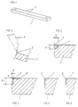
- FIG. 1 shows a cutting bar 11 in the accompanying drawings their cutting edges 2, as counter blades in a chopper can be mounted.
- Fig. 2 shows a cutting bar 11 with their Cutting edges 2 and a knife 3, which by rotation on the Cutting bar 11 is moved past.
- Fig. 3 shows a grass cutting bar according to the state of the art.
- 4, 5 and 6 show several Variants of the cutting bar according to the invention.
- the Hard material bar 7 can e.g. by means of plasma deposition welding on the Cutting body 1 to be welded.
- the hard material strip 7 can also, as in FIG. 5, only partially in the Cutter body 1 used or on the cutter body as in Fig. 6 1 put on. It is not absolutely necessary that the hard coating is arranged laterally to the cutting edge 2, but in the same way, the hard coating can also be on the Provide the top of the cutter body 1.
Landscapes
- Life Sciences & Earth Sciences (AREA)
- Environmental Sciences (AREA)
- Crushing And Pulverization Processes (AREA)
- Mechanical Treatment Of Semiconductor (AREA)
- Turning (AREA)
- Polishing Bodies And Polishing Tools (AREA)
- Manufacture Of Alloys Or Alloy Compounds (AREA)
Abstract
Description
Claims (14)
- Schheidleiste bestehend aus einem Schneidenkörper mit mindestens einer eine Schneidkante aufweisenden Hartstoffleiste, dadurch gekennzeichnet, daß die Hartstoffleiste (7) aus einer zähen Matrix mit darin eingelagerten Hartstoffpartikeln besteht und auf den Schneidenkörper (1) aufgeschweißt ist.
- Schneidleiste nach Anspruch 1, dadurch gekennzeichnet, daß die Matrix eine Härte von maximal 600 HV, vorzugsweise 480 - 580 HV, aufweist.
- Schneidleiste nach Anspruch 1 oder 2, dadurch gekennzeichnet, daß die Matrix aus einer Kombination von zwei oder mehreren der chemischen Elemente, Nickel, Silicium, Kohlenstoff und Bor, besteht.
- Schneidleiste nach Anspruch 1, 2 oder 3, dadurch gekennzeichnet, daß die Hartstoffpartikel eine Härte von größer 1800 HV aufweisen.
- Schneidleiste nach Anspruch 4, dadurch gekennzeichnet, daß die Hartstoffpartikel Wolframschmelzkarbide sind.
- Schneidleiste nach einem der vorhergehenden Ansprüche, dadurch gekennzeichnet, daß der Anteil der Hartstoffpartikel in der Hartstoffleiste (7) größer 50 Gew.% ist.
- Schneidleiste nach einem der vorhergehenden Ansprüche, dadurch gekennzeichnet, daß der Flächenanteil der Hartstoffpartikel mit einem Durchmesser von 40 - 160 µm im Schliffbild der Hartstoffleiste (7) mindestens 30% ist.
- Schneidleiste nach einem der vorhergehenden Ansprüche, dadurch gekennzeichnet, daß die Hartstoffpartikel in der Matrix gleichmäßig verteilt sind.
- Schneidleiste nach einem der vorhergehenden Ansprüche, dadurch gekennzeichnet, daß die Hartstoffleiste (7) eine Dicke (8) von 2 bis 3,5 mm aufweist.
- Schneidleiste nach einem der vorhergehenden Ansprüche, dadurch gekennzeichnet, daß die Hartsoffleiste (7) seitlich am Schneidenkörper (1) aufgeschweißt ist.
- Schneidleiste nach einem der vorhergehenden Ansprüche, dadurch gekennzeichnet, daß die Hartstoffleiste (7) eine Breite (9) von mindestens 6 mm hat.
- Schneidleiste nach einem der vorhergehenden Ansprüche, dadurch gekennzeichnet, daß die Hartstoffleiste (7) durch Auftragsschweißen am Schneidenkörper (1) aufgeschweißt ist.
- Schneidleiste nach einem der vorhergehenden Ansprüche, dadurch gekennzeichnet, daß die Hartstoffleiste (7) eine Haftungsfestigkeit von mehr als 100 N/mm2 aufweist.
- Schneidleiste nach einem der vorhergehenden Ansprüche, dadurch gekennzeichnet, daß die Hartstoffleiste (7) auf der Oberseite am Schneidenkörper (1) aufgeschweißt ist.
Priority Applications (1)
| Application Number | Priority Date | Filing Date | Title |
|---|---|---|---|
| AT98108318T ATE296534T1 (de) | 1997-05-16 | 1998-05-07 | Schneidleiste |
Applications Claiming Priority (3)
| Application Number | Priority Date | Filing Date | Title |
|---|---|---|---|
| AT0084397A AT405475B (de) | 1997-05-16 | 1997-05-16 | Schneidleiste |
| AT843/97 | 1997-05-16 | ||
| AT84397 | 1997-05-16 |
Publications (3)
| Publication Number | Publication Date |
|---|---|
| EP0878123A2 true EP0878123A2 (de) | 1998-11-18 |
| EP0878123A3 EP0878123A3 (de) | 2001-12-19 |
| EP0878123B1 EP0878123B1 (de) | 2005-06-01 |
Family
ID=3501055
Family Applications (1)
| Application Number | Title | Priority Date | Filing Date |
|---|---|---|---|
| EP98108318A Expired - Lifetime EP0878123B1 (de) | 1997-05-16 | 1998-05-07 | Schneidleiste |
Country Status (3)
| Country | Link |
|---|---|
| EP (1) | EP0878123B1 (de) |
| AT (2) | AT405475B (de) |
| DE (1) | DE59812823D1 (de) |
Cited By (5)
| Publication number | Priority date | Publication date | Assignee | Title |
|---|---|---|---|---|
| EP1264535A1 (de) * | 2001-06-05 | 2002-12-11 | Lund International b.v. | Schneidleiste für Feldhäcksler |
| FR2832288A1 (fr) * | 2001-11-22 | 2003-05-23 | Alain Bon | Dispositif de hachage pour ensileuse |
| EP1935231A1 (de) * | 2006-12-20 | 2008-06-25 | CLAAS Selbstfahrende Erntemaschinen GmbH | Häckselmesser für landwirtschaftliche Erntemaschinen |
| EP2319669A3 (de) * | 2009-11-05 | 2013-11-06 | Busatis GmbH | Messer zur tangentialen Entfernung einer Oberfläche eines Werkstücks |
| US20220087109A1 (en) * | 2020-09-21 | 2022-03-24 | Gebrüder Busatis Gesellschaft M.B.H. | Cutting element |
Families Citing this family (1)
| Publication number | Priority date | Publication date | Assignee | Title |
|---|---|---|---|---|
| PL233914B1 (pl) | 2015-05-15 | 2019-12-31 | Dominik Janicki | Sposób wykonania noży do sieczkarni, zwłaszcza stalnic |
Citations (1)
| Publication number | Priority date | Publication date | Assignee | Title |
|---|---|---|---|---|
| AT398509B (de) | 1992-03-05 | 1994-12-27 | Busatis Geb Gmbh | Gegenschneide, insbesondere für häckselmaschinen |
Family Cites Families (9)
| Publication number | Priority date | Publication date | Assignee | Title |
|---|---|---|---|---|
| US2033594A (en) * | 1931-09-24 | 1936-03-10 | Stoody Co | Scarifier tooth |
| US3023490A (en) * | 1955-11-25 | 1962-03-06 | Dawson Armoring Company | Armored metal articles with a thin hard film made in situ and conforming to the exact contour of the underlying surface |
| US3045934A (en) * | 1961-08-18 | 1962-07-24 | Paper Calmenson & Co | Surface hardening for hammermill hammers |
| US3635271A (en) * | 1970-08-26 | 1972-01-18 | Deere & Co | Cutterhead and shear bar for forage harvesters |
| US3805660A (en) * | 1973-01-15 | 1974-04-23 | Gehl Co | Shear bar for forage harvesters or the like |
| DE8703479U1 (de) * | 1986-12-08 | 1987-07-23 | Veltmann, Bernhard, 4530 Ibbenbüren | Schneid- und Schlagwerkzeug, insbesondere Fräsmesser, für den Einsatz in der Land- und Forstwirtschaft, Gartenbau und Kulturpflege |
| DE8700403U1 (de) * | 1987-01-09 | 1987-05-14 | Karl Mengele & Söhne Maschinenfabrik und Eisengießerei GmbH & Co, 8870 Günzburg | Gegenschneide |
| DE3734781A1 (de) * | 1987-10-14 | 1989-04-27 | Knedla Richard | Verfahren zur herstellung einer schicht mit schaerfender wirkung an schneidkanten von scherblaettern |
| GB2264033B (en) * | 1992-02-12 | 1994-06-01 | Atco Qualcast Ltd | Cylinder lawnmowers |
-
1997
- 1997-05-16 AT AT0084397A patent/AT405475B/de not_active IP Right Cessation
-
1998
- 1998-05-07 DE DE59812823T patent/DE59812823D1/de not_active Expired - Lifetime
- 1998-05-07 AT AT98108318T patent/ATE296534T1/de not_active IP Right Cessation
- 1998-05-07 EP EP98108318A patent/EP0878123B1/de not_active Expired - Lifetime
Patent Citations (1)
| Publication number | Priority date | Publication date | Assignee | Title |
|---|---|---|---|---|
| AT398509B (de) | 1992-03-05 | 1994-12-27 | Busatis Geb Gmbh | Gegenschneide, insbesondere für häckselmaschinen |
Cited By (7)
| Publication number | Priority date | Publication date | Assignee | Title |
|---|---|---|---|---|
| EP1264535A1 (de) * | 2001-06-05 | 2002-12-11 | Lund International b.v. | Schneidleiste für Feldhäcksler |
| US6637687B2 (en) | 2001-06-05 | 2003-10-28 | Lund International B.V. | Shearbar for a forage harvester |
| FR2832288A1 (fr) * | 2001-11-22 | 2003-05-23 | Alain Bon | Dispositif de hachage pour ensileuse |
| EP1935231A1 (de) * | 2006-12-20 | 2008-06-25 | CLAAS Selbstfahrende Erntemaschinen GmbH | Häckselmesser für landwirtschaftliche Erntemaschinen |
| EP2319669A3 (de) * | 2009-11-05 | 2013-11-06 | Busatis GmbH | Messer zur tangentialen Entfernung einer Oberfläche eines Werkstücks |
| US20220087109A1 (en) * | 2020-09-21 | 2022-03-24 | Gebrüder Busatis Gesellschaft M.B.H. | Cutting element |
| US12337493B2 (en) * | 2020-09-21 | 2025-06-24 | Gebrüder Busatis Gesellschaft M.B.H. | Cutting element with self-resharpening cutting edge |
Also Published As
| Publication number | Publication date |
|---|---|
| EP0878123B1 (de) | 2005-06-01 |
| DE59812823D1 (de) | 2005-07-07 |
| AT405475B (de) | 1999-08-25 |
| ATA84397A (de) | 1999-01-15 |
| ATE296534T1 (de) | 2005-06-15 |
| EP0878123A3 (de) | 2001-12-19 |
Similar Documents
| Publication | Publication Date | Title |
|---|---|---|
| DE3700250C2 (de) | ||
| EP1214979B1 (de) | Fräszahn für eine Zerkleinerungsmaschine | |
| EP0875323B1 (de) | Hartstoffbeschichtung für Messer oder Schneiden | |
| EP1434654A2 (de) | Fräszahn sowie fräszahnhalter für eine zerkleinerungsmaschine | |
| EP2387873B1 (de) | Land- oder forstwirtschaftliches messer aus mehrschichtstahl | |
| EP3401048B1 (de) | Sägeblatt für eine säge zum schneiden von stängeligem halmgut | |
| AT405475B (de) | Schneidleiste | |
| EP0904686A1 (de) | Häckselmesser | |
| EP3701781B1 (de) | Einsatz aus hartmetall für eine landwirtschaftliche vorrichtung | |
| DD260178A3 (de) | Schneidmesser fuer erntemaschinen | |
| AT398509B (de) | Gegenschneide, insbesondere für häckselmaschinen | |
| AT1642U2 (de) | Schneidleiste | |
| DE3327895C2 (de) | Drehbare Mähscheibe | |
| DE3826984C2 (de) | Mähscheibe | |
| EP3569315B1 (de) | Zerkleinerungsvorrichtung | |
| BE1021638B1 (de) | Feldhäcksler mit reibboden. | |
| DE202008018560U1 (de) | Schneidmesser für einen Kreiselmäher sowie Kreiselmäher mit einem derartigen Schneidmesser | |
| EP3984645B1 (de) | Schneidelement | |
| DE2154469A1 (de) | Schneidemesser fuer rasenmaeher | |
| DE8810945U1 (de) | Vorrichtung zum Schneiden von Schaumstoff | |
| DE102023114417A1 (de) | Messerblatt für Freischneider | |
| AT15150U1 (de) | Kombinierte Gegenschneide | |
| DE19838738A1 (de) | Messerträger für ein Rasenbearbeitungsgerät | |
| DE3400424A1 (de) | Schneidwerk | |
| DE3209061A1 (de) | Hackmaschine |
Legal Events
| Date | Code | Title | Description |
|---|---|---|---|
| PUAI | Public reference made under article 153(3) epc to a published international application that has entered the european phase |
Free format text: ORIGINAL CODE: 0009012 |
|
| AK | Designated contracting states |
Kind code of ref document: A2 Designated state(s): AT BE CH CY DE DK ES FI FR GB GR IE IT LI LU MC NL PT SE Kind code of ref document: A2 Designated state(s): AT BE DE FR |
|
| AX | Request for extension of the european patent |
Free format text: AL;LT;LV;MK;RO;SI |
|
| PUAL | Search report despatched |
Free format text: ORIGINAL CODE: 0009013 |
|
| AK | Designated contracting states |
Kind code of ref document: A3 Designated state(s): AT BE CH CY DE DK ES FI FR GB GR IE IT LI LU MC NL PT SE |
|
| AX | Request for extension of the european patent |
Free format text: AL;LT;LV;MK;RO;SI |
|
| 17P | Request for examination filed |
Effective date: 20020315 |
|
| 17Q | First examination report despatched |
Effective date: 20020716 |
|
| AKX | Designation fees paid |
Free format text: AT BE DE FR |
|
| GRAP | Despatch of communication of intention to grant a patent |
Free format text: ORIGINAL CODE: EPIDOSNIGR1 |
|
| GRAS | Grant fee paid |
Free format text: ORIGINAL CODE: EPIDOSNIGR3 |
|
| GRAA | (expected) grant |
Free format text: ORIGINAL CODE: 0009210 |
|
| AK | Designated contracting states |
Kind code of ref document: B1 Designated state(s): AT BE DE FR |
|
| REG | Reference to a national code |
Ref country code: IE Ref legal event code: FG4D Free format text: LANGUAGE OF EP DOCUMENT: GERMAN |
|
| REF | Corresponds to: |
Ref document number: 59812823 Country of ref document: DE Date of ref document: 20050707 Kind code of ref document: P |
|
| ET | Fr: translation filed | ||
| PLBE | No opposition filed within time limit |
Free format text: ORIGINAL CODE: 0009261 |
|
| STAA | Information on the status of an ep patent application or granted ep patent |
Free format text: STATUS: NO OPPOSITION FILED WITHIN TIME LIMIT |
|
| PG25 | Lapsed in a contracting state [announced via postgrant information from national office to epo] |
Ref country code: AT Free format text: LAPSE BECAUSE OF NON-PAYMENT OF DUE FEES Effective date: 20060507 |
|
| 26N | No opposition filed |
Effective date: 20060302 |
|
| REG | Reference to a national code |
Ref country code: DE Ref legal event code: R082 Ref document number: 59812823 Country of ref document: DE Representative=s name: PUCHBERGER, BERGER & PARTNER, AT |
|
| REG | Reference to a national code |
Ref country code: DE Ref legal event code: R079 Ref document number: 59812823 Country of ref document: DE Free format text: PREVIOUS MAIN CLASS: A01F0029200000 Ipc: A01F0029000000 |
|
| REG | Reference to a national code |
Ref country code: DE Ref legal event code: R082 Ref document number: 59812823 Country of ref document: DE Representative=s name: PUCHBERGER & PARTNER PATENTANWAELTE, AT Effective date: 20140813 Ref country code: DE Ref legal event code: R082 Ref document number: 59812823 Country of ref document: DE Representative=s name: PUCHBERGER, BERGER & PARTNER, AT Effective date: 20140813 Ref country code: DE Ref legal event code: R081 Ref document number: 59812823 Country of ref document: DE Owner name: GEBRUEDER BUSATIS GESELLSCHAFT M.B.H., AT Free format text: FORMER OWNER: BUSATIS GMBH, PURGSTALL, AT Effective date: 20140813 Ref country code: DE Ref legal event code: R079 Ref document number: 59812823 Country of ref document: DE Free format text: PREVIOUS MAIN CLASS: A01F0029200000 Ipc: A01F0029000000 Effective date: 20140826 |
|
| REG | Reference to a national code |
Ref country code: FR Ref legal event code: TP Owner name: GEBRUDER BUSATIS GESELLSCHAFT M.B.H., AT Effective date: 20140922 |
|
| REG | Reference to a national code |
Ref country code: FR Ref legal event code: PLFP Year of fee payment: 19 |
|
| REG | Reference to a national code |
Ref country code: FR Ref legal event code: PLFP Year of fee payment: 20 |
|
| PGFP | Annual fee paid to national office [announced via postgrant information from national office to epo] |
Ref country code: DE Payment date: 20170508 Year of fee payment: 20 Ref country code: FR Payment date: 20170523 Year of fee payment: 20 |
|
| PGFP | Annual fee paid to national office [announced via postgrant information from national office to epo] |
Ref country code: BE Payment date: 20170519 Year of fee payment: 20 |
|
| REG | Reference to a national code |
Ref country code: DE Ref legal event code: R071 Ref document number: 59812823 Country of ref document: DE |
|
| REG | Reference to a national code |
Ref country code: BE Ref legal event code: PD Free format text: DETAILS ASSIGNMENT: CHANGE OF OWNER(S), AFFECTATION / CESSION Effective date: 20140814 Ref country code: BE Ref legal event code: MK Effective date: 20180507 |