EP0878340A2 - Appareil de commande de la force motrice d'un véhicule - Google Patents
Appareil de commande de la force motrice d'un véhicule Download PDFInfo
- Publication number
- EP0878340A2 EP0878340A2 EP98108555A EP98108555A EP0878340A2 EP 0878340 A2 EP0878340 A2 EP 0878340A2 EP 98108555 A EP98108555 A EP 98108555A EP 98108555 A EP98108555 A EP 98108555A EP 0878340 A2 EP0878340 A2 EP 0878340A2
- Authority
- EP
- European Patent Office
- Prior art keywords
- engine
- output
- air
- fuel ratio
- microprocessor
- Prior art date
- Legal status (The legal status is an assumption and is not a legal conclusion. Google has not performed a legal analysis and makes no representation as to the accuracy of the status listed.)
- Granted
Links
Images


Classifications
-
- B—PERFORMING OPERATIONS; TRANSPORTING
- B60—VEHICLES IN GENERAL
- B60K—ARRANGEMENT OR MOUNTING OF PROPULSION UNITS OR OF TRANSMISSIONS IN VEHICLES; ARRANGEMENT OR MOUNTING OF PLURAL DIVERSE PRIME-MOVERS IN VEHICLES; AUXILIARY DRIVES FOR VEHICLES; INSTRUMENTATION OR DASHBOARDS FOR VEHICLES; ARRANGEMENTS IN CONNECTION WITH COOLING, AIR INTAKE, GAS EXHAUST OR FUEL SUPPLY OF PROPULSION UNITS IN VEHICLES
- B60K28/00—Safety devices for propulsion-unit control, specially adapted for, or arranged in, vehicles, e.g. preventing fuel supply or ignition in the event of potentially dangerous conditions
- B60K28/10—Safety devices for propulsion-unit control, specially adapted for, or arranged in, vehicles, e.g. preventing fuel supply or ignition in the event of potentially dangerous conditions responsive to conditions relating to the vehicle
- B60K28/16—Safety devices for propulsion-unit control, specially adapted for, or arranged in, vehicles, e.g. preventing fuel supply or ignition in the event of potentially dangerous conditions responsive to conditions relating to the vehicle responsive to, or preventing, spinning or skidding of wheels
-
- B—PERFORMING OPERATIONS; TRANSPORTING
- B60—VEHICLES IN GENERAL
- B60W—CONJOINT CONTROL OF VEHICLE SUB-UNITS OF DIFFERENT TYPE OR DIFFERENT FUNCTION; CONTROL SYSTEMS SPECIALLY ADAPTED FOR HYBRID VEHICLES; ROAD VEHICLE DRIVE CONTROL SYSTEMS FOR PURPOSES NOT RELATED TO THE CONTROL OF A PARTICULAR SUB-UNIT
- B60W10/00—Conjoint control of vehicle sub-units of different type or different function
- B60W10/04—Conjoint control of vehicle sub-units of different type or different function including control of propulsion units
- B60W10/06—Conjoint control of vehicle sub-units of different type or different function including control of propulsion units including control of combustion engines
-
- B—PERFORMING OPERATIONS; TRANSPORTING
- B60—VEHICLES IN GENERAL
- B60W—CONJOINT CONTROL OF VEHICLE SUB-UNITS OF DIFFERENT TYPE OR DIFFERENT FUNCTION; CONTROL SYSTEMS SPECIALLY ADAPTED FOR HYBRID VEHICLES; ROAD VEHICLE DRIVE CONTROL SYSTEMS FOR PURPOSES NOT RELATED TO THE CONTROL OF A PARTICULAR SUB-UNIT
- B60W30/00—Purposes of road vehicle drive control systems not related to the control of a particular sub-unit, e.g. of systems using conjoint control of vehicle sub-units
- B60W30/18—Propelling the vehicle
- B60W30/18172—Preventing, or responsive to skidding of wheels
-
- F—MECHANICAL ENGINEERING; LIGHTING; HEATING; WEAPONS; BLASTING
- F02—COMBUSTION ENGINES; HOT-GAS OR COMBUSTION-PRODUCT ENGINE PLANTS
- F02D—CONTROLLING COMBUSTION ENGINES
- F02D41/00—Electrical control of supply of combustible mixture or its constituents
- F02D41/02—Circuit arrangements for generating control signals
- F02D41/021—Introducing corrections for particular conditions exterior to the engine
-
- F—MECHANICAL ENGINEERING; LIGHTING; HEATING; WEAPONS; BLASTING
- F02—COMBUSTION ENGINES; HOT-GAS OR COMBUSTION-PRODUCT ENGINE PLANTS
- F02D—CONTROLLING COMBUSTION ENGINES
- F02D41/00—Electrical control of supply of combustible mixture or its constituents
- F02D41/02—Circuit arrangements for generating control signals
- F02D41/14—Introducing closed-loop corrections
- F02D41/1438—Introducing closed-loop corrections using means for determining characteristics of the combustion gases; Sensors therefor
- F02D41/1473—Introducing closed-loop corrections using means for determining characteristics of the combustion gases; Sensors therefor characterised by the regulation method
- F02D41/1475—Regulating the air fuel ratio at a value other than stoichiometry
-
- F—MECHANICAL ENGINEERING; LIGHTING; HEATING; WEAPONS; BLASTING
- F02—COMBUSTION ENGINES; HOT-GAS OR COMBUSTION-PRODUCT ENGINE PLANTS
- F02D—CONTROLLING COMBUSTION ENGINES
- F02D41/00—Electrical control of supply of combustible mixture or its constituents
- F02D41/02—Circuit arrangements for generating control signals
- F02D41/14—Introducing closed-loop corrections
- F02D41/1438—Introducing closed-loop corrections using means for determining characteristics of the combustion gases; Sensors therefor
- F02D41/1486—Introducing closed-loop corrections using means for determining characteristics of the combustion gases; Sensors therefor with correction for particular operating conditions
-
- F—MECHANICAL ENGINEERING; LIGHTING; HEATING; WEAPONS; BLASTING
- F02—COMBUSTION ENGINES; HOT-GAS OR COMBUSTION-PRODUCT ENGINE PLANTS
- F02D—CONTROLLING COMBUSTION ENGINES
- F02D41/00—Electrical control of supply of combustible mixture or its constituents
- F02D41/30—Controlling fuel injection
- F02D41/3011—Controlling fuel injection according to or using specific or several modes of combustion
- F02D41/3017—Controlling fuel injection according to or using specific or several modes of combustion characterised by the mode(s) being used
- F02D41/3023—Controlling fuel injection according to or using specific or several modes of combustion characterised by the mode(s) being used a mode being the stratified charge spark-ignited mode
- F02D41/3029—Controlling fuel injection according to or using specific or several modes of combustion characterised by the mode(s) being used a mode being the stratified charge spark-ignited mode further comprising a homogeneous charge spark-ignited mode
-
- F—MECHANICAL ENGINEERING; LIGHTING; HEATING; WEAPONS; BLASTING
- F02—COMBUSTION ENGINES; HOT-GAS OR COMBUSTION-PRODUCT ENGINE PLANTS
- F02D—CONTROLLING COMBUSTION ENGINES
- F02D41/00—Electrical control of supply of combustible mixture or its constituents
- F02D41/30—Controlling fuel injection
- F02D41/3011—Controlling fuel injection according to or using specific or several modes of combustion
- F02D41/3076—Controlling fuel injection according to or using specific or several modes of combustion with special conditions for selecting a mode of combustion, e.g. for starting, for diagnosing
Definitions
- This invention relates to drive force control for preventing slip of drive wheels of a vehicle equipped with a lean burn engine.
- a drive force controller or a traction control system which prevents drive wheels from slipping during acceleration of a vehicle so as to prevent acceleration performance from falling, for example decreases the output of an engine according to slip of the drive wheels.
- This decrease in output is obtained for example by closing the opening of a second throttle which is disposed in an intake passage of the engine in series with the first throttle, stopping injection of fuel to specific cylinders, or retarding a fuel ignition timing.
- Tokkai Hei 8-144803 published by the Japanese Patent Office in 1996, discloses a drive force controller for a lean burn engine in which combustion is performed at a leaner air-fuel ratio than a stoichiometric air-fuel ratio, and fuel cut is performed by stopping fuel injection to specific cylinders of the engine.
- the engine operation is apt to become unstable.
- the lean burn system is adopted in a direct injection gasoline engine wherein gasoline is directly injected into a cylinder, fuel cut operation easily causes unstable engine operation.
- uniform combustion is performed at an ordinary air-fuel ratio in the vicinity of the stoichiometric air-fuel ratio, and stratified combustion is performed with a lean air-fuel ratio.
- the air-fuel ratio in stratified combustion is even leaner than the lean air-fuel ratio of an ordinary lean burn engine and stratified combustion therefore requires a large intake air volume.
- the output reduction of the engine due to fuel cut may also become excessive when there are only a few cylinders in the engine.
- this invention provides a vehicle drive force control device comprising a fuel injection valve for injecting fuel into an engine, a mechanism for varying the output of the engine, sensors for detecting a slip of a drive wheel, and a microprocessor.
- the microprocessor is programmed to selectively control an air-fuel ratio of an air-fuel mixture supplied to the engine via the fuel injection valve so that the air-fuel ratio is equal to either an ordinary air-fuel ratio which is approximately equal to a stoichiometric air-fuel ratio, or a lean air fuel ratio leaner than the ordinary air-fuel ratio, control the output varying mechanism so as to reduce the output of the engine when a slip of the drive wheel is detected, and control the air-fuel ratio of the air-fuel mixture to the ordinary air-fuel ratio as the output of the engine is reduced by the output varying mechanism.
- the microprocessor is further programmed to return the air-fuel ratio of the air-fuel mixture to an air-fuel ratio before the output reduction of the engine was started by the output varying mechanism when the output reduction of the engine by the output varying mechanism has terminated.
- the device further comprises a sensor for detecting a load state of the engine, and the microprocessor is further programmed to control a variation rate of the air-fuel ratio between the ordinary air-fuel ratio and the lean air-fuel ratio according to the load state of the engine.
- the load detecting sensor comprises a sensor for detecting either an intake air amount of the engine or a rotation speed of the engine.
- the output varying mechanism comprises the fuel injection valve which stops fuel injection according to a signal from the microprocessor, and the microprocessor is further programmed to count a number of fuel injection valves in which fuel injection has stopped, and control a variation rate of the air-fuel ratio between the ordinary air-fuel ratio and a lean air-fuel ratio according to the number.
- the output varying mechanism comprises either of the fuel injection valve which stops fuel injection according to a signal from the microprocessor, and a throttle for reducing an intake air amount of the engine according to a signal from the microprocessor.
- microprocessor is further programmed to calculate a target engine output and control the output varying mechanism so that the output of the engine coincides with the target engine output.
- This invention also provides a vehicle drive force control device comprising a fuel injection valve for injecting fuel into an engine, a mechanism for varying the output of the engine, sensors for detecting a slip of a drive wheel, and a microprocessor.
- the microprocessor is programmed to selectively control a combustion state of the engine either to uniform combustion or to stratified combustion via the fuel injection valve, control the output varying mechanism so as to reduce the output of the engine when a slip of the drive wheel is detected, and control the combustion state of the engine to uniform combustion as the output of the engine is reduced by the output varying mechanism.
- the microprocessor is further programmed to return the combustion state of the engine to a combustion state before the output reduction of the engine was started by the output varying mechanism when the output reduction of the engine by the output varying mechanism has terminated.
- the device further comprises a sensor for detecting a load state of the engine, and the microprocessor is further programmed to control a variation rate of the combustion state between the uniform combustion and stratified combustion according to the load state of the engine.
- the load detecting sensor comprises a sensor for detecting either an intake air amount of the engine or a rotation speed of the engine.
- the output varying mechanism comprises the fuel injection valve which stops fuel injection according to a signal from the microprocessor, and the microprocessor is further programmed to count a number of fuel injection valves in which fuel injection has stopped, and control a variation rate of the combustion state between the uniform combustion and stratified combustion according to the number.
- the output varying mechanism comprises either the fuel injection valve which stops fuel injection according to a signal from the microprocessor, or a throttle for reducing an intake air amount of the engine according to a signal from the microprocessor.
- the output varying mechanism comprises a throttle for reducing an intake air amount of the engine according to a signal from the microprocessor, and the microprocessor is further programmed to control an opening of the throttle to an opening corresponding to the uniform combustion at a first rate, and subsequently control the opening corresponding to the signal at a second rate slower than the first rate, as the output of the engine is reduced by the output varying mechanism.
- microprocessor is further programmed to calculate a target engine output, and control the output varying mechanism so that the output of the engine coincides with the target engine output.
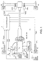
- Fig. 1 is a schematic diagram of a drive force control device according to this invention.
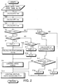
- Fig. 2 is a flowchart to explain a drive force control process performed by a TCS controller and engine controller with which the control device is equipped.
- Fig. 3 is a timing chart describing an air-fuel ratio change when the control device starts drive force control.
- Fig. 4 is a timing chart describing an air-fuel ratio change when the control device terminates drive force control.
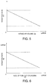
- Fig. 5 is a map stored by the TCS controller showing a relation between an intake air amount Qa and a variation rate K1 of air-fuel ratio.
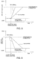
- Fig. 6 is a map stored by the TCS controller showing a relation between a number of fuel cut cylinders and a variation rate of air-fuel ratio.
- Fig. 7 is similar to Fig. 2, but showing a second embodiment of this invention.
- Fig. 8 is similar to Fig. 3, but showing the second embodiment of this invention.
- Fig. 9 is similar to Fig. 4, but showing the second embodiment of this invention.
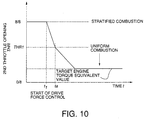
- Fig. 10 is a timing chart showing a variation of a throttle opening THR of a second throttle when drive force control starts in a control device according to the second embodiment.
- a drive force control device for a vehicle is provided with a TCS controller 1 and an engine controller 2 respectively comprising a micro computer.
- the engine controller 2 selectively applies an ordinary air-fuel ratio in the vicinity of the stoichiometric air-fuel ratio or a lean air-fuel ratio according to the running state of the vehicle, and performs air-fuel ratio control and ignition timing control of the engine 4 by outputting a fuel injection signal to a fuel injection valve 14 provided in each cylinder of the engine.
- the engine 4 transmits a drive force to the rear wheels RR, RL via a transmission.
- the left and right rear wheels RL, RR are the drive wheels
- the left and right front wheels FL, FR are the driven wheels.
- a first throttle 8 which is opened and closed according to the depression of an accelerator pedal 7 and a second throttle 10 controlled via actuator 9 by the TCS controller 1, are arranged in series in an intake passage of the engine 4.
- the opening TVO of the first throttle 8 is detected by a throttle opening sensor 11, and is output as a signal to the TCS controller 1 and engine controller 2.
- a depression amount of the accelerator pedal 7 may be detected instead of the throttle opening TVO .
- An air flow meter 13 is provided in the intake passage.
- the air flow meter 13 detects an intake air amount Qa of the intake passage, and this is input into the engine controller 2.
- An engine rotation speed Ne which is detected by a crank angle sensor 15 is input into the engine controller 2.
- the TCS controller 1 detects a slip of the drive wheels RR, RL based on wheel speeds VWFR , VWFL , VWRR , VWRL , and a drive force control request signal is output to the engine controller 2 when the drive wheels RR, RL slip.
- the engine controller 2 thereby controls the output of the engine 4 by performing fuel cut in a specific cylinder or cylinders and by performing air-fuel ratio control described hereafter as in the aforesaid prior art example.
- a second throttle opening THR is calculated, and the TCS controller 1 modifies the opening of the second throttle 10 via an actuator 9. Due to this, the intake air amount Qa is made to vary according to a target engine output torque.
- This process is performed at a predetermined interval, e.g. 10 milliseconds.
- the TCS controller 1 reads the output of the wheel speed sensors 12FR - 12RL, and calculates the wheel speeds VWFR , VWFL , VWRR , VWRL .
- the engine controller 2 reads the rotation speed Ne of the engine 4, opening TVO of the first throttle 8 and intake air amount Qa .
- an average velocity Vwf of a driven wheel is found as a mean of the wheel speeds VWFR and VWFL of the left and right front wheels FL and FR.
- an average velocity Vwr of the drive wheels is found as the average value of the wheel speeds VWRR , VWRL of the left and right rear wheels RL, RR.
- a target drive wheel speed Vws which is a target value of drive force control is found by adding a predetermined value ⁇ to a driven wheel average speed Vwf representing a current vehicle speed.
- Vws Vwf + ⁇ where, ⁇ is preferably set within the range of 2 - 5Km/hr.
- a step S5 it is determined whether or not the drive wheels are slipping by comparing the average drive wheel speed Vwr with the target drive wheel speed Vws .
- step S6 it is determined whether or not the present air-fuel ratio of the air-fuel mixture supplied by the engine controller 2 to the engine 4 is larger than the ordinary air-fuel ratio, i.e. it is determined whether or not the vehicle is being driven with a lean air-fuel ratio. This can be determined for example from the above-mentioned air-fuel ratio control data.
- the routine proceeds to a step S7 and then to a step S8 after setting a lean flag FLB to 1.
- the routine proceeds to a step S10.
- a parameter K for describing a variation rate from the present air-fuel ratio to the ordinary air-fuel ratio is calculated according to the engine rotation speed Ne .
- the variation rate K is set to be small the higher the engine rotation speed Ne as shown In Fig. 3.
- K is represented by the slopes of the solid lines.
- a map of this type is stored beforehand in the engine controller 2, and the engine controller 2 calculates this rate K by referring to the map based on the engine rotation speed Ne in the step S8.
- the routine proceeds to the step S10, it is determined whether or not the lean flag FLB set on the immediately preceding occasion that the process was performed, is set to 1.
- the routine proceeds to the step S8 in case of 1, and when the flag FLB is not 1, the lean flag is set to 0 in a step S11.
- the processing of the steps S6 - S8, S10 - S12 is performed by the engine controller 2.
- the TCS controller 1 calculates a slip rate S of the drive wheels by the following equation.
- S Vwr / Vwf
- the TCS controller 1 determines the second throttle opening THR according to this slip rate S .
- the engine controller 2 determines a number of cylinders FC in which fuel cut is performed corresponding to the drive force control request signal output by the TCS controller 1 according to this slip rate S .
- the number of fuel cut cylinders FC and the second throttle opening THR are respectively calculated by referring to preset maps. For this purpose, a map of the second throttle opening THR is prestored by the TCS controller 1, and a map of the number of fuel cut cylinders FC is prestored by the engine controller 2.
- the engine controller 2 After having performed drive force control in the step S9, the engine controller 2 makes the air-fuel ratio vary toward the ordinary air-fuel ratio based on the variation rate K in a step S13.
- step S5 it is determined whether or not the lean flag FLB is 1 in the step S14.
- FLB 1
- drive force control is not performed, and the variation rate - K is set in a step S15 to return the air-fuel ratio from the ordinary air-fuel ratio to the lean air-fuel ratio depending on the running conditions.
- a step S17 It is determined whether or not the air-fuel ratio is lean. When the air-fuel ratio is not lean, the routine immediately proceeds to a step S13. In the step S13, air-fuel ratio control tending to lean is performed based on the variation rate - K .
- the routine proceeds to the step S13.
- the variation rate K is 0 in this case, air-fuel ratio control is not actually performed in the step S13.
- the routine proceeds to the step S13.
- the variation rate K is 0 also in this case, air-fuel ratio control is not actually performed in the step S13.
- the output torque of the engine 4 increases as the air-fuel ratio varies from the lean air-fuel ratio to the ordinary air-fuel ratio in the vicinity of the stoichiometric air-fuel ratio. Excessive fluctuation of the output torque is suppressed by making the variation of air-fuel ratio smoother the higher the engine rotation speed Ne .
- drive force control is completed at a time t 2 when the slip of the drive wheels converges as shown in Fig. 4. If the air-fuel ratio before start of drive force control is lean, as the lean flag FLB is set to 1 in the step S7, the processing of the steps S14, S15, S17 is performed, and a change-over from the ordinary air-fuel ratio to the lean air-fuel ratio takes place.
- This change-over is performed at the variation rate - K according to the engine rotation speed Ne , and the air-fuel ratio which was temporarily changed over from lean to the ordinary air-fuel ratio due to drive force control, is smoothly returned to the lean air-fuel ratio.
- a variation rate K1 based on the intake air amount Qa shown in Fig. 5 may be used.
- a variation rate K2 based on the number of fuel cut cylinders shown in Fig. 6 may also be used.
- the variation rate K1 is set to decrease the larger the intake air amount Qa
- the variation rate K2 is set to decrease the larger the number of fuel cut cylinders.
- the engine rotation speed Ne , intake air amount Qa and number of fuel cut cylinders FC are all values concerned with engine load, and the air-fuel ratio is set to shift more gradually from the lean air-fuel ratio to the ordinary air-fuel ratio the larger the engine load.
- Figs. 7 - 10 show a second embodiment of this invention.
- This embodiment is applied to a lean burn, direct injection type engine.
- This engine selectively performs uniform combustion with an ordinary air-fuel ratio in the vicinity of the stoichiometric air-fuel ratio, and stratified combustion with a lean air-fuel ratio.
- the air-fuel ratio is even leaner than in an engine wherein fuel is injected into the intake passage as in the aforesaid first embodiment.
- the flowchart of Fig. 7 resembles the flowchart of Fig. 2 of the aforesaid first embodiment, but differs in the following respects.
- the steps S6 and S17 are replaced by steps S6', S17'.
- a step S20 for calculating the target engine torque is inserted between the step S5 and step S6'.
- the step S9 for performing drive force control is also replaced by a step S9'.
- the step S13 for air-fuel ratio control is replaced by a step S13'.
- the remaining steps are the same as those of the aforesaid first embodiment.
- step S5 When, as shown in Fig. 8, a slip of the drive wheels is detected at the timing t 1 during running at a lean air-fuel ratio in stratified combustion (step S5), the drive force control of the step S20 and subsequent steps starts.
- a target drive torque which can suppress slip of the drive wheels is calculated based on the intake air amount Qa assuming a uniform combustion state, i.e. the ordinary air-fuel ratio.
- a function or a map specifying a relation between the engine rotation speed Ne and intake air amount Qa in the uniform combustion state is prestored in the engine controller 2.
- step S6' it is determined whether or not stratified combustion is performed.
- the lean flag FLB is set to 1 in the step S7. Also in the step S8, the air-fuel ratio variation rate K is calculated.
- the air -fuel ratio variation rate K is set according to engine rotation speed or load as in the case of the aforesaid first embodiment as shown in Fig. 8.
- the variation rate K is set to a small value, and when rotation speed or load is small, the variation rate K is set to a large value.
- the second throttle opening THR corresponding to the target engine torque calculated in the step S20 is found from a map previously stored in the engine controller 2, and the second throttle 10 is driven in the closing direction via the actuator 9 based on the second throttle opening THR .
- the second throttle 10 is rapidly driven in the closing direction until an opening TR1 when the intake air amount becomes equal to an air amount according to the ordinary air-fuel ratio.
- the second throttle 10 is driven in the closing direction more gradually than before the timing ta until a target engine torque equivalent value is reached. Fuel cut as in the aforesaid first embodiment is also performed in parallel with the operation of this second throttle 10.
- step S13' the air-fuel ratio is controlled in the same manner as in the step S13 of the first embodiment. Fuel injection timing is also controlled in this step S13' to control the combustion state of the engine 4 toward uniform combustion or stratified combustion.
- the output torque starts to increase from when the air-fuel ratio changes from very lean in the stratified combustion state to the ordinary air-fuel ratio in the vicinity of the stoichiometric air-fuel ratio.
- the intake air volume of the second throttle 10 is reduced, an excessive change of the output torque is suppressed. In this way, smooth drive force control is achieved even in a direct injection type engine.
- the calculation of target engine torque need be performed only for the ordinary air-fuel ratio, so the calculation is simple, and it can be performed with speed and high precision.
- the air-fuel ratio variation rate - K is set according to engine rotation speed or load as in the case of the aforesaid first embodiment, and the air-fuel ratio shifts smoothly from an ordinary air-fuel ratio to a lean air-fuel ratio according to this variation rate - K .
Landscapes
- Engineering & Computer Science (AREA)
- Chemical & Material Sciences (AREA)
- Combustion & Propulsion (AREA)
- Mechanical Engineering (AREA)
- General Engineering & Computer Science (AREA)
- Transportation (AREA)
- Automation & Control Theory (AREA)
- Control Of Vehicle Engines Or Engines For Specific Uses (AREA)
- Electrical Control Of Air Or Fuel Supplied To Internal-Combustion Engine (AREA)
- Auxiliary Drives, Propulsion Controls, And Safety Devices (AREA)
Applications Claiming Priority (3)
| Application Number | Priority Date | Filing Date | Title |
|---|---|---|---|
| JP121993/97 | 1997-05-13 | ||
| JP12199397 | 1997-05-13 | ||
| JP12199397A JP3709652B2 (ja) | 1997-05-13 | 1997-05-13 | 車両用駆動力制御装置 |
Publications (3)
| Publication Number | Publication Date |
|---|---|
| EP0878340A2 true EP0878340A2 (fr) | 1998-11-18 |
| EP0878340A3 EP0878340A3 (fr) | 2000-04-05 |
| EP0878340B1 EP0878340B1 (fr) | 2003-12-10 |
Family
ID=14824916
Family Applications (1)
| Application Number | Title | Priority Date | Filing Date |
|---|---|---|---|
| EP98108555A Expired - Lifetime EP0878340B1 (fr) | 1997-05-13 | 1998-05-11 | Appareil de commande de la force motrice d'un véhicule |
Country Status (5)
| Country | Link |
|---|---|
| US (1) | US6079511A (fr) |
| EP (1) | EP0878340B1 (fr) |
| JP (1) | JP3709652B2 (fr) |
| KR (1) | KR100316357B1 (fr) |
| DE (1) | DE69820335T2 (fr) |
Families Citing this family (3)
| Publication number | Priority date | Publication date | Assignee | Title |
|---|---|---|---|---|
| JP3960339B2 (ja) * | 2005-01-11 | 2007-08-15 | トヨタ自動車株式会社 | 吸入空気量ばらつき検出装置 |
| JP2006348826A (ja) * | 2005-06-15 | 2006-12-28 | Yanmar Co Ltd | 燃料噴射制御装置 |
| JP6973111B2 (ja) * | 2018-01-23 | 2021-11-24 | マツダ株式会社 | エンジンの制御方法及びエンジンシステム |
Citations (1)
| Publication number | Priority date | Publication date | Assignee | Title |
|---|---|---|---|---|
| JPH08144803A (ja) | 1994-11-19 | 1996-06-04 | Mazda Motor Corp | エンジンの制御装置 |
Family Cites Families (7)
| Publication number | Priority date | Publication date | Assignee | Title |
|---|---|---|---|---|
| JP2813045B2 (ja) * | 1990-07-17 | 1998-10-22 | マツダ株式会社 | エンジンの出力制御装置 |
| DE4328835C2 (de) * | 1993-08-27 | 2002-09-05 | Bosch Gmbh Robert | Zylinderselektives Einspritzsystem |
| DE4400259B4 (de) * | 1994-01-07 | 2005-09-01 | Robert Bosch Gmbh | Steuereinrichtung für zylinderindividuelle Kraftstoffeinspritzung |
| DE4407475C2 (de) * | 1994-03-07 | 2002-11-14 | Bosch Gmbh Robert | Verfahren und Vorrichtung zur Steuerung eines Fahrzeugs |
| DE19546554C1 (de) * | 1995-12-13 | 1997-02-27 | Daimler Benz Ag | Verfahren und Vorrichtung zur Motormomentregelung |
| JP3563869B2 (ja) * | 1996-03-25 | 2004-09-08 | トヨタ自動車株式会社 | エンジン出力制御装置 |
| JP3536523B2 (ja) * | 1996-04-19 | 2004-06-14 | 日産自動車株式会社 | 車両用駆動力制御装置 |
-
1997
- 1997-05-13 JP JP12199397A patent/JP3709652B2/ja not_active Expired - Lifetime
-
1998
- 1998-04-06 KR KR1019980012019A patent/KR100316357B1/ko not_active Expired - Lifetime
- 1998-05-07 US US09/073,938 patent/US6079511A/en not_active Expired - Lifetime
- 1998-05-11 DE DE69820335T patent/DE69820335T2/de not_active Expired - Lifetime
- 1998-05-11 EP EP98108555A patent/EP0878340B1/fr not_active Expired - Lifetime
Patent Citations (1)
| Publication number | Priority date | Publication date | Assignee | Title |
|---|---|---|---|---|
| JPH08144803A (ja) | 1994-11-19 | 1996-06-04 | Mazda Motor Corp | エンジンの制御装置 |
Also Published As
| Publication number | Publication date |
|---|---|
| JPH10311233A (ja) | 1998-11-24 |
| JP3709652B2 (ja) | 2005-10-26 |
| US6079511A (en) | 2000-06-27 |
| EP0878340A3 (fr) | 2000-04-05 |
| EP0878340B1 (fr) | 2003-12-10 |
| KR100316357B1 (ko) | 2002-04-24 |
| DE69820335D1 (de) | 2004-01-22 |
| DE69820335T2 (de) | 2004-06-03 |
| KR19980086569A (ko) | 1998-12-05 |
Similar Documents
| Publication | Publication Date | Title |
|---|---|---|
| US6002979A (en) | Traction control system for automotive vehicles | |
| EP0294634B1 (fr) | Système anti-patinage des roues motrices pour véhicules | |
| US6199005B1 (en) | Vehicle drive force control device | |
| US5813936A (en) | Driving force controller in vehicle for forcibly upshifting in response to a driving force traction controller and a vehicle stopped detection means | |
| US5366039A (en) | Acceleration slip control device for a motor vehicle | |
| US5829544A (en) | Drive force reduction controller for vehicle | |
| US6115663A (en) | Drive power control device for vehicle | |
| JPH0693893A (ja) | 加速スリップ制御装置 | |
| EP0334371B1 (fr) | Système de commande de patinage de roue motrice pour véhicule | |
| US5311433A (en) | Acceleration slip control device for a vehicle | |
| EP0878340B1 (fr) | Appareil de commande de la force motrice d'un véhicule | |
| JP2913822B2 (ja) | 加速スリップ制御装置 | |
| US5899290A (en) | Engine output control apparatus | |
| JPS6223831A (ja) | 車両の加速スリツプ制御装置 | |
| JPH0942001A (ja) | 内燃機関の回転数制御装置 | |
| JPS61129432A (ja) | 車両の加速スリツプ制御装置 | |
| JP3204079B2 (ja) | 車両用駆動力制御装置 | |
| JPS61116033A (ja) | 車両の加速スリツプ制御装置 | |
| JP2820171B2 (ja) | 車両用内燃機関の燃料制御装置 | |
| KR100222879B1 (ko) | 자동 변속기 자동차의 기어 변속시 엔진 토오크 제어방법 | |
| JPH0654095B2 (ja) | 車両の加速スリツプ制御装置 | |
| EP0886059B1 (fr) | Contrôleur de force motrice pour véhicule | |
| JP2514545Y2 (ja) | 駆動力制御装置 | |
| JPS62121838A (ja) | 車両のスリツプ制御装置 | |
| JP2658559B2 (ja) | 車両のスリップ制御装置 |
Legal Events
| Date | Code | Title | Description |
|---|---|---|---|
| PUAI | Public reference made under article 153(3) epc to a published international application that has entered the european phase |
Free format text: ORIGINAL CODE: 0009012 |
|
| 17P | Request for examination filed |
Effective date: 19980511 |
|
| AK | Designated contracting states |
Kind code of ref document: A2 Designated state(s): DE FR GB |
|
| AX | Request for extension of the european patent |
Free format text: AL;LT;LV;MK;RO;SI |
|
| PUAL | Search report despatched |
Free format text: ORIGINAL CODE: 0009013 |
|
| AK | Designated contracting states |
Kind code of ref document: A3 Designated state(s): AT BE CH CY DE DK ES FI FR GB GR IE IT LI LU MC NL PT SE |
|
| AX | Request for extension of the european patent |
Free format text: AL;LT;LV;MK;RO;SI |
|
| RIC1 | Information provided on ipc code assigned before grant |
Free format text: 7B 60K 28/16 A, 7F 02D 41/14 B, 7F 02D 41/30 B, 7F 02D 41/36 B, 7F 02D 41/02 B |
|
| AKX | Designation fees paid |
Free format text: DE FR GB |
|
| 17Q | First examination report despatched |
Effective date: 20020529 |
|
| GRAH | Despatch of communication of intention to grant a patent |
Free format text: ORIGINAL CODE: EPIDOS IGRA |
|
| GRAS | Grant fee paid |
Free format text: ORIGINAL CODE: EPIDOSNIGR3 |
|
| GRAA | (expected) grant |
Free format text: ORIGINAL CODE: 0009210 |
|
| AK | Designated contracting states |
Kind code of ref document: B1 Designated state(s): DE FR GB |
|
| REG | Reference to a national code |
Ref country code: GB Ref legal event code: FG4D |
|
| REF | Corresponds to: |
Ref document number: 69820335 Country of ref document: DE Date of ref document: 20040122 Kind code of ref document: P |
|
| ET | Fr: translation filed | ||
| PLBE | No opposition filed within time limit |
Free format text: ORIGINAL CODE: 0009261 |
|
| STAA | Information on the status of an ep patent application or granted ep patent |
Free format text: STATUS: NO OPPOSITION FILED WITHIN TIME LIMIT |
|
| 26N | No opposition filed |
Effective date: 20040913 |
|
| REG | Reference to a national code |
Ref country code: FR Ref legal event code: PLFP Year of fee payment: 19 |
|
| REG | Reference to a national code |
Ref country code: FR Ref legal event code: PLFP Year of fee payment: 20 |
|
| PGFP | Annual fee paid to national office [announced via postgrant information from national office to epo] |
Ref country code: GB Payment date: 20170510 Year of fee payment: 20 Ref country code: FR Payment date: 20170413 Year of fee payment: 20 Ref country code: DE Payment date: 20170502 Year of fee payment: 20 |
|
| REG | Reference to a national code |
Ref country code: DE Ref legal event code: R071 Ref document number: 69820335 Country of ref document: DE |
|
| REG | Reference to a national code |
Ref country code: GB Ref legal event code: PE20 Expiry date: 20180510 |
|
| PG25 | Lapsed in a contracting state [announced via postgrant information from national office to epo] |
Ref country code: GB Free format text: LAPSE BECAUSE OF EXPIRATION OF PROTECTION Effective date: 20180510 |