EP0878351A1 - Dispositif et procédé pour la fixation des charges cylindriques - Google Patents
Dispositif et procédé pour la fixation des charges cylindriques Download PDFInfo
- Publication number
- EP0878351A1 EP0878351A1 EP97108050A EP97108050A EP0878351A1 EP 0878351 A1 EP0878351 A1 EP 0878351A1 EP 97108050 A EP97108050 A EP 97108050A EP 97108050 A EP97108050 A EP 97108050A EP 0878351 A1 EP0878351 A1 EP 0878351A1
- Authority
- EP
- European Patent Office
- Prior art keywords
- edge
- load
- cargo
- halves
- web
- Prior art date
- Legal status (The legal status is an assumption and is not a legal conclusion. Google has not performed a legal analysis and makes no representation as to the accuracy of the status listed.)
- Withdrawn
Links
- 238000000034 method Methods 0.000 title claims description 7
- 230000001012 protector Effects 0.000 claims description 31
- 238000004804 winding Methods 0.000 claims description 12
- 239000002131 composite material Substances 0.000 description 3
- 230000006378 damage Effects 0.000 description 3
- 210000002414 leg Anatomy 0.000 description 3
- 238000005452 bending Methods 0.000 description 2
- 238000002347 injection Methods 0.000 description 2
- 239000007924 injection Substances 0.000 description 2
- 239000004743 Polypropylene Substances 0.000 description 1
- 238000004873 anchoring Methods 0.000 description 1
- 230000000694 effects Effects 0.000 description 1
- 239000000463 material Substances 0.000 description 1
- 230000013011 mating Effects 0.000 description 1
- 230000002093 peripheral effect Effects 0.000 description 1
- 239000004033 plastic Substances 0.000 description 1
- -1 polypropylene Polymers 0.000 description 1
- 229920001155 polypropylene Polymers 0.000 description 1
- 230000002787 reinforcement Effects 0.000 description 1
- 230000000284 resting effect Effects 0.000 description 1
- 238000005096 rolling process Methods 0.000 description 1
- 239000000243 solution Substances 0.000 description 1
- 230000006641 stabilisation Effects 0.000 description 1
- 238000011105 stabilization Methods 0.000 description 1
- 210000002435 tendon Anatomy 0.000 description 1
- 210000000689 upper leg Anatomy 0.000 description 1
- 238000005303 weighing Methods 0.000 description 1
Images




Classifications
-
- B—PERFORMING OPERATIONS; TRANSPORTING
- B60—VEHICLES IN GENERAL
- B60P—VEHICLES ADAPTED FOR LOAD TRANSPORTATION OR TO TRANSPORT, TO CARRY, OR TO COMPRISE SPECIAL LOADS OR OBJECTS
- B60P7/00—Securing or covering of load on vehicles
- B60P7/06—Securing of load
- B60P7/08—Securing to the vehicle floor or sides
- B60P7/12—Securing to the vehicle floor or sides the load being tree-trunks, beams, drums, tubes, or the like
-
- B—PERFORMING OPERATIONS; TRANSPORTING
- B65—CONVEYING; PACKING; STORING; HANDLING THIN OR FILAMENTARY MATERIAL
- B65D—CONTAINERS FOR STORAGE OR TRANSPORT OF ARTICLES OR MATERIALS, e.g. BAGS, BARRELS, BOTTLES, BOXES, CANS, CARTONS, CRATES, DRUMS, JARS, TANKS, HOPPERS, FORWARDING CONTAINERS; ACCESSORIES, CLOSURES, OR FITTINGS THEREFOR; PACKAGING ELEMENTS; PACKAGES
- B65D71/00—Bundles of articles held together by packaging elements for convenience of storage or transport, e.g. portable segregating carrier for plural receptacles such as beer cans or pop bottles; Bales of material
- B65D71/02—Arrangements of flexible binders
- B65D71/04—Arrangements of flexible binders with protecting or supporting elements arranged between binder and articles or materials, e.g. for preventing chafing of binder
Definitions
- the invention relates to a method and a device for securing loads of essentially cylindrical piece goods with an opening at the front, ie for example paper rolls with a hollow winding core etc.
- paper rolls are preferably spoken of directly, although also sheet coils, barrel-shaped piece goods and the like in this way can be secured.
- Such cargo is due to the weight and the large anyway Dimensions directly on the loading areas of railway wagons or trucks put on, and must there against slipping, especially across the direction of travel, secured, which is usually done by tension belts by the Loading area, on which they are firmly anchored and tensioned, over the cargo, so the paper roll is tensioned.
- the Lashing straps mostly on the outer edges of the loading area, i.e. on Outer frame profile of the chassis or on corresponding lashing rails of the truck.
- two Rows can be arranged side by side, or the roles are offset, so along a zigzag line running in the direction of travel on the loading area arranged. Also an arrangement in two layers one above the other or standing, staggered or exactly one above the other is common, with the roles can be placed directly on top of one another and tensioning from the loading area only happens across the top layer of the rolls. Even in the direction of travel juxtaposed roles with a tension belt from left to right consistently stretched over all adjacent roles.
- Another mode of transport is the lying transport, in which the paper rolls rest with their outer surface on the loading surface.
- the axis of the Paper roll may be arranged transversely to the direction of travel or parallel to this.
- the paper rolls must be rolled away using appropriate wheel chocks etc. be reliably secured.
- the bracing takes place again across the highest point of each roll of paper using the usual Lashing straps.
- the device has edge protection on the one hand and on the other hand, an extension that fits into the front opening of the Loaded goods, usually the high winding core of a paper roll, the Diameter fluctuates between about 7 and just under 15 cm, engages, and the both parts are connected by a web, on the one hand, damage the edge of the paper roll prevented by the belt and on the other hand also a
- the tension belt slips away from the target position, which is particularly reliable caused by projections or other guide elements on the device is a change in position of the strap across its longitudinal direction prevent.
- the device is divided into two halves, which each extend from the center to the outer circumference of a paper roll, whereby for standing paper rolls the two halves together the same paper roll can be used if the Loading area is only a roll of paper.
- a positive connection between the halves on the one hand a simple Assembled to the overall device achieved and on the other hand a kink-resistant Forming the connection of the two halves, in particular one Pushing together an undercut shape, such as one Dovetail shape etc. across the length of the device is preferred, and also across the plane of the one to be placed on it Tension belt.
- the two halves of the device are preferably identical, to always combine any two parts together to form the entire device can.
- the individual half is in particular designed to be variable in length by the To be able to use the device with rolls of different diameters. It preferably consists of an upper part and a lower part are guided telescopically into each other, and being on the lower part the extension engaging in the winding core and on the upper part that on the The outer edge of the paper roll is preferably in one piece is molded. As a result, the lower and upper parts can each be injection molded be inexpensively made of plastic.
- the extensions are shaped and dimensioned so that one out of two Halves composite overall device the resulting Total extension from the extensions of the two halves in total the smallest winding core opening can be used.
- the tension belt which rests on the web, not only through it lateral extensions, but is led by tabs that are closed Form profile, completely encompassed.
- the tension belt with its free end through it Straps threaded through, and into the tensioning ratchet of the other belt part, the is in turn attached to the vehicle, inserted and tensioned.
- the edge of the paper roll is not only protected by the edge protection has a significantly greater width than the width of the tension belt, and thus the surface pressures on the paper roll decrease. Rather is additional an undercut is worked into the inside edge of the edge protector, which Outer edges of the outermost layers of paper can end freely.
- the The inside of the edge protector is concavely curved to rest on the convex Lateral surface of the paper roll, the curvature of the edge protector - in Viewing direction of the axis of the paper roll viewed - is less than the curvature the jacket length of the largest paper roll to be secured, so that always an attachment edge protection in the central area of the paper roll is guaranteed.
- the outside of the edge protector over which the tensioning belt runs, rounded as much as possible, i.e. with a radius of at least 7 mm, preferably more than 12 mm.
- - is under supervision looking at the device - the outer edge over which the tension belt is deflected, not crowned, but straight, so that the tension belt over its entire width rests on this outer radius and evenly over the presses the entire width of the tension belt.
- the tabs also serve on the one hand the passage and thus the lateral guidance of the tension belt, on the other hand, the sliding and telescopic connection of the upper part and lower part.
- one of the tabs is used, which is usually on the lower part are designed as a stop for a nose on the upper part to prevent the upper part can be pulled out completely from the lower part.
- the tabs are usually on the lower part are designed as a stop for a nose on the upper part to prevent the upper part can be pulled out completely from the lower part.
- the web protrude in the longitudinal direction at the edges Web walls on which a lateral sliding of the on the top of the web prevent the tension belt from being attached.
- the jetty can improve the Rigidity must be ribbed on the underside.
- the extension at the end of the device facing away from the edge protection, at two-part, telescopic design, preferably arranged on the lower part, is in the top view, i.e. in the direction of the central axis of the paper roll, approximately semicircular with the chord of the semicircle towards the free end. This tendon protrudes on one side of the center line of the web dovetail-shaped projection, and at the same distance on the other side is an equivalent dovetail shape Bulge arranged.
- the Edge protection is preferably arranged on the upper part, the outer edge of the Edge protection over which the tension belt is placed and its force on the Acts on the outer edge of the paper roll, not lower, but at least the same high, if not higher than that area of the device in which the Extension is arranged, which is then on the lower part. This is reliably ensures that the pressure of the tension belt is primary, especially exclusively, on the edge protection and thus the outer edges of the paper roll act, and no contact pressure on the central area, i.e. the central core, the Paper roll.
- the operator may have to do so first the two halves by plugging together the extensions connect one unit, next the resulting overall process the two halves in the front opening of the paper roll or of the other cargo.
- the edge protection in there Bring the system to the outer edge of the paper roll.
- the tensioning belt can now be inserted or threaded in afterwards take place or already after putting the two halves of the Device have happened.
- the free end of the tension belt is placed in a tensioning unit introduced and used this tensioning unit for tightening the tension belt, whereby the tension belt firmly on the outside of the device and in particular is pressed onto the outside of the edge protector of the device and thereby the paper roll presses reliably against the loading area.
- the two halves do not become one Entire device plugged together, but separately on each outside, so different paper rolls attached or on different end faces of the same, lying paper roll, in this Arrangement to pull the same lashing strap through both halves and to tighten.
- Fig. 1 shows a securing device with an edge protector 10 and Extension 11, which at the respective ends of an intermediate web 12th are molded.
- the web 12 can be made telescopic, so that the Distance between the edge protector 10 and the extension 11 at the respective Paper roll radius can be adjusted.
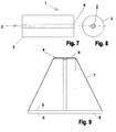
- This securing device is usually used on paper rolls 1, such as they are shown in Fig. 7. If the The edge protection device 10 is in the area of the edge 5 of the securing device Paper roll 1 applied, while the extension 11 in FIG. 1 pointing downward an end opening 2 in the core of the paper roll 1 through the hollow Winding core is formed, is used and the web 12 the wound Paper webs spanned in the radial direction on the front side.
- a safety device of this embodiment is particularly used when paper rolls lying flat, d. H. with its lateral surface 3 lying are transported as shown in Fig. 11.
- a tension belt 7 runs above the paper roll 1 horizontally along the lateral surface 3 and then over the edge protector 10 obliquely downwards to the outer edges of the loading area 6, on which it is braced is.
- FIG. 13 shows a paper roll 1, which, although also lying flat, however, with its longitudinal axis oriented in the direction of travel 18, on the loading surface 6 the truck 8 is.
- This paper roll 1 is laterally against rolling away secured by wedges 32 or other limitations, but must against Sliding forward - provided that it is not placed against a fixed front wall etc. can be - also secured by a strap 7.
- the tension belt 7 runs along this horizontally through the middle of the End face extending device, and from there, so from the respective the side edge protection 10 of the device from obliquely to the rear below, where anchoring to the vehicle by means of appropriate hooks etc. is available.
- this embodiment can be used advantageously if several paper rolls 1 standing on their end faces 4 in several rows are arranged side by side.
- Fig. 10 two standing on their end faces 4 paper rolls 1 are shown are each secured with a safety device a, b.
- the extensions 11 of the Safety devices are each in the front opening 2 of the Paper roll core used and the edge protector 10 is in the range of Outer edges 5 placed, the respective webs 12 starting from the Show extensions 11 in opposite directions radially outwards.
- the respective webs 12 are oriented transversely to the direction of travel 18 of the car, so that the two rollers 1 with the tension belt 7 transversely to the direction of travel 18th can be braced.
- the paper rolls 1 in two layers, saddled up, so to speak, on top of each other by placing the paper rolls of the second layer just above the joint between two paper rolls of the lower layer.
- the paper rolls of the lower one Layers are spaced from each other and are against each other Rolled apart secured, for example by resting on an end wall on one side and on the other side by means of an underlying wedge 32, if the axial direction of the paper rolls is oriented transversely to the direction of travel.
- the upper paper rolls 1 ' are secured by moving from the center above each, that is, in the two end faces of this upper paper roll 1 ', one Safety device a, b is inserted.
- Each of the securing devices a, b extends from the hollow winding core in Center of the upper paper roll 1 ', in which the extension 11 of the device is located vertically upwards, so that the edge protector 10 of the device on highest point of the peripheral edge of the end face of the upper paper roll 1 ' is present.
- the tension belt 7 usually runs vertically from the loading area above, ie over the center and along the web 2 of the device to Edge protection 10, where the deflection into the horizontal along the top Surface line of the upper roll of paper 1 'takes place, and on the opposite Analog face down.
- FIG. 2 Another embodiment of the securing device in FIG. 2 consists of two identical halves a, b, which on the extensions 11a, 11b with each other are connected. At least one of the webs 12a, 12b is telescopic (not shown) so that the two edge protectors 10a, 10b diametrically aligned opposite to the respective circumference of the paper roll 1 can be.
- the space requirement of the extensions 11 is such that they are also small usual roll cores can be used.
- connection of the two halves a, b is constructed so that their extensions can be connected to form a unit by plugging them together can also moderate forces in the transverse direction, for. B. buckling forces can and thereby stabilize the safety device.
- FIGS. 1-6 Constructional details of the device can be seen in FIGS. 1-6.
- a device is shown in side view, of which one in the length of the non-changeable web 12 in the same direction at one end of the Protect edge protector 10 and at the other end of the extension 11, which in the Opening 2 of the paper roll or the load can be inserted.
- FIG. 2 shown in the top view, namely in two coupled together Copies.
- These two halves a, b are on their extension 11 on the End face of the longitudinal direction of the device on one side of the longitudinal center with an undercut recess 28 'and on the other side with a analog positively shaped projection 28 equipped.
- the individual device as shown in FIG. 1 or in FIG. 2 as Designated half a and b, each in two parts for the purpose of Length variability can be formed, as shown in Figures 3-6 is.
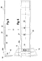
- Each of the devices consists of a lower part 16, as in Fig. 3 and 4 shown in side view and top view, and an upper part 17, as in Fig. 5 and 6 shown in side view and top view.
- the web 12 is divided into two, the lower part of Figures 3 and 4 on one end carries the extension 11 down from the plane of the web 12 protrudes.
- the web 12 consists essentially of a plate-shaped Material used to improve stabilization at the bottom Transverse ribs 22 and also on the outside, in the longitudinal direction 9 has longitudinal ribs, since the entire lower part - and that too Entire upper part 17 - can be produced as an injection molded part, preferably from polypropylene should be.
- the top of the web 12 on which the Upper part 17 should be performed is the top of the web 12 on which the Upper part 17 should be performed. This is done primarily through U-shaped tabs 23a, 23b, the outer edge to outer edge on the top of the plate-shaped web 12 sit and together with this on all sides form a closed contour. Since one of the tabs 23b is close to the extension side End is arranged and the other tab 23a at the other end is through these tabs 23a, 23b and those protruding along the longitudinal edges Web walls 29, between which the upper part 17 is then located, the upper part guided precisely in the longitudinal direction 9 on the lower part 16.
- the two Parts are displaceable in the longitudinal direction 9 with respect to one another and are nevertheless captive by a nose 30 is formed in the assembled state on the upper part 17, the is in the assembled state between the tabs 23a and 23b, and when pulling the upper part 17 and lower part 16 completely apart front tab 23a abuts. Because of a one-sided bevel on the nose 30 can be the top part 17 despite the nose 30 under the first assembly this tab 23a are pushed through, which is slightly deformed, pulling out, however, is only with active pre-deformation of this tab 23a, and therefore not possible in normal operation.
- the extension 11 protrudes from the plane of the web 12 in the direction opposite the tabs 23a, 23b. 4 that the extension 11 has a substantially semicircular outer contour, the chord of which forms the end of the web 11.
- an undercut recess 28 in particular in each case dovetail-shaped, is formed. Due to the same design and the same distance from the longitudinal center 31, two lower parts 16 can thus be coupled in a form-fitting manner, as in the example of the one-piece device of FIG. 1, as shown in the application of FIG. 2 using the example of FIG. 1.
- the upper part matching the lower part 16, at one end of which the edge protector 10 is formed, is shown in a side view in FIG. 5.
- the web 12 is again essentially configured as a plate-shaped component with transverse ribs 22 and longitudinal ribs on the underside.
- web walls 21 protrude upwards, but this time they have a different function, namely the lateral guidance of the tension belt 7 inserted in the assembled state on the top of this upper part 17.
- the clear distance between the web walls 21 on the top side is somewhat larger than that Width of a standard tension belt 7.
- a tab 23c protrudes again at the end on the edge protection side - similar to that above tabs 23a and 23b of the lower part 16 - upwards which also the tension belt 7 must be passed.
- the amount of Web 12 - including the web walls 21 - in the side view of FIG. 5 must be less than the clear height of the tabs 23a, 23b of the lower part 16, through which they must be led.
- the edge protector 10 itself, one from the plane of the web 12 in substantially downward at right angles, that is from the tab 23c from the Opposing direction, representing thighs, has special features: one is the edge protector 10 viewed in the supervision of FIG. 6 essential wider than the web 12.
- edge protector 10 points upward in its interior angle Undercut 15 directed to the outermost layers of the paper roll face not to damage.
- Edge protection 10 not straight, but at least on its against the Paper roll facing inside with a concave curvature 13, which is slightly less than the curvature of the largest paper roll to be secured.
- the edge protector 10 is always in contact with the respective one Paper roll in the middle, ie near the longitudinal center 31, guaranteed.
- edge protector 10 is close to the inner angle, that is edge protection-side end region of the web 12 for reinforcement with longitudinal ribs 24 equipped, which are lower than the bottom of the leg 12 in the rest Area, so that the rest of the area from the lower part 16 is passed.
- the outer edge of the edge protector 10 - 5 - over which the tension belt 7 is placed is rounded, with a radius 14 of at least 7, preferably at least 12, ideally about 15 mm.
- the web walls 21 on the top of the web 12 of the upper part 17 extend around this radius 14 around along the round strutting leg of the edge protector 10 in essentially to its lower, free end.
- the edge protector 10 is still - in line with the tab 23c - outside their width, ie outside the width of the web 12 - by Corresponding ribbing on the top is statically reinforced.
Landscapes
- Engineering & Computer Science (AREA)
- Mechanical Engineering (AREA)
- Transportation (AREA)
- Replacement Of Web Rolls (AREA)
Priority Applications (1)
| Application Number | Priority Date | Filing Date | Title |
|---|---|---|---|
| EP97108050A EP0878351A1 (fr) | 1997-05-16 | 1997-05-16 | Dispositif et procédé pour la fixation des charges cylindriques |
Applications Claiming Priority (1)
| Application Number | Priority Date | Filing Date | Title |
|---|---|---|---|
| EP97108050A EP0878351A1 (fr) | 1997-05-16 | 1997-05-16 | Dispositif et procédé pour la fixation des charges cylindriques |
Publications (1)
| Publication Number | Publication Date |
|---|---|
| EP0878351A1 true EP0878351A1 (fr) | 1998-11-18 |
Family
ID=8226801
Family Applications (1)
| Application Number | Title | Priority Date | Filing Date |
|---|---|---|---|
| EP97108050A Withdrawn EP0878351A1 (fr) | 1997-05-16 | 1997-05-16 | Dispositif et procédé pour la fixation des charges cylindriques |
Country Status (1)
| Country | Link |
|---|---|
| EP (1) | EP0878351A1 (fr) |
Cited By (3)
| Publication number | Priority date | Publication date | Assignee | Title |
|---|---|---|---|---|
| WO2001058718A1 (fr) * | 2000-02-11 | 2001-08-16 | Permar Oy | Procede et appareil de fixation de rouleaux de papier |
| EP1281570A1 (fr) * | 2001-08-01 | 2003-02-05 | Terje Thon Stenli | Dispositif de fixation de cargaison en forme de tonneau ou similaire |
| GB2537363B (en) * | 2015-04-12 | 2020-02-26 | Pulse Plastics Ltd | Protector |
Citations (6)
| Publication number | Priority date | Publication date | Assignee | Title |
|---|---|---|---|---|
| DE125969C (fr) * | ||||
| DE425314C (de) * | 1924-05-01 | 1926-02-15 | Aluminium Walzwerke Singen Fa | Verpackung fuer Metallfolie in Rollenform |
| US3637234A (en) * | 1969-09-10 | 1972-01-25 | Phillips Petroleum Co | Edge protector |
| DE8520270U1 (de) * | 1985-07-13 | 1985-10-03 | Thorwarth & Grebe oHG, 5927 Erndtebrück | Stützwange für auf rohrförmigen Trägerkernen sitzende Folienwickel |
| US5236087A (en) * | 1991-10-01 | 1993-08-17 | Morgan Royston P | Ferrous metal coil edge and lap protector |
| GB2267477A (en) * | 1992-06-05 | 1993-12-08 | Richard Allan Jones | Paper roll spacer |
-
1997
- 1997-05-16 EP EP97108050A patent/EP0878351A1/fr not_active Withdrawn
Patent Citations (6)
| Publication number | Priority date | Publication date | Assignee | Title |
|---|---|---|---|---|
| DE125969C (fr) * | ||||
| DE425314C (de) * | 1924-05-01 | 1926-02-15 | Aluminium Walzwerke Singen Fa | Verpackung fuer Metallfolie in Rollenform |
| US3637234A (en) * | 1969-09-10 | 1972-01-25 | Phillips Petroleum Co | Edge protector |
| DE8520270U1 (de) * | 1985-07-13 | 1985-10-03 | Thorwarth & Grebe oHG, 5927 Erndtebrück | Stützwange für auf rohrförmigen Trägerkernen sitzende Folienwickel |
| US5236087A (en) * | 1991-10-01 | 1993-08-17 | Morgan Royston P | Ferrous metal coil edge and lap protector |
| GB2267477A (en) * | 1992-06-05 | 1993-12-08 | Richard Allan Jones | Paper roll spacer |
Cited By (3)
| Publication number | Priority date | Publication date | Assignee | Title |
|---|---|---|---|---|
| WO2001058718A1 (fr) * | 2000-02-11 | 2001-08-16 | Permar Oy | Procede et appareil de fixation de rouleaux de papier |
| EP1281570A1 (fr) * | 2001-08-01 | 2003-02-05 | Terje Thon Stenli | Dispositif de fixation de cargaison en forme de tonneau ou similaire |
| GB2537363B (en) * | 2015-04-12 | 2020-02-26 | Pulse Plastics Ltd | Protector |
Similar Documents
| Publication | Publication Date | Title |
|---|---|---|
| DE2636160A1 (de) | Endlosfoerderer | |
| WO2017140549A1 (fr) | Support à roulettes et dispositif de transport | |
| WO1994005860A1 (fr) | Rail de guidage courbe | |
| EP0596219B1 (fr) | Procédé de jonction d'éxtremités de convoies transporteurs et élément de jonction correspondant | |
| EP3625153A2 (fr) | Module de transport, moyen de traction, convoyeur à plaques et procédé | |
| EP0314176A2 (fr) | Dispositif de chargement pour véhicule de transport | |
| EP0391247A2 (fr) | Convoyeur à bande portant des rouleaux d'accumulation | |
| EP1733955A1 (fr) | Dispositif d'immobilisation de charge | |
| DE202024104545U1 (de) | Ladungssicherungsvorrichtung für Kabeltrommeln | |
| DE69300265T2 (de) | Einrichtung an Planen. | |
| DE19815095C1 (de) | Spannkante | |
| DE4026157A1 (de) | Befestigungsvorrichtung | |
| EP0473953B1 (fr) | Transporteur de courroie | |
| EP2910418B1 (fr) | Dispositif de sécurisation de charge pour un véhicule utilitaire | |
| DE3817756C1 (en) | Guide rail for guide rollers of hoist installations | |
| EP0982188B1 (fr) | Système de sécurité pour véhicule de transport et dispositif de fixation sur rails dans un véhicule de transport | |
| DE4425572C2 (de) | Aufprallträger für Seitenteile von Fahrzeugen | |
| EP1510234A2 (fr) | Dispositif d'étayage | |
| AT407412B (de) | Vorrichtung mit einem schalschloss für die verbindung von verstärkungsträgern von schalplatten | |
| DE4304555C1 (de) | Verbindungsstück zur klemmenden Verbindung zweier senkrecht zueinander angeordneter Profilstücke eines Fördergestells | |
| EP3666567A1 (fr) | Rideau latéral pour camion-remorque, camion-remorque et camion avec camion-remorque | |
| DE2611175B2 (de) | Chlauchbefestigungsvorrichtung | |
| DE4130273C2 (fr) | ||
| DE202025103276U1 (de) | Anordnung zur Ladungssicherung in einem beweglichen Laderaum, und Fahrzeuganhänger | |
| CH696584A5 (de) | Fördervorrichtung für Regalkanäle von Regallageranlagen. |
Legal Events
| Date | Code | Title | Description |
|---|---|---|---|
| PUAI | Public reference made under article 153(3) epc to a published international application that has entered the european phase |
Free format text: ORIGINAL CODE: 0009012 |
|
| 17P | Request for examination filed |
Effective date: 19980518 |
|
| AK | Designated contracting states |
Kind code of ref document: A1 Designated state(s): AT BE DE FR IT LU NL |
|
| AKX | Designation fees paid |
Free format text: AT BE DE FR IT LU NL |
|
| 17Q | First examination report despatched |
Effective date: 19990816 |
|
| GRAG | Despatch of communication of intention to grant |
Free format text: ORIGINAL CODE: EPIDOS AGRA |
|
| GRAG | Despatch of communication of intention to grant |
Free format text: ORIGINAL CODE: EPIDOS AGRA |
|
| GRAG | Despatch of communication of intention to grant |
Free format text: ORIGINAL CODE: EPIDOS AGRA |
|
| GRAG | Despatch of communication of intention to grant |
Free format text: ORIGINAL CODE: EPIDOS AGRA |
|
| GRAH | Despatch of communication of intention to grant a patent |
Free format text: ORIGINAL CODE: EPIDOS IGRA |
|
| STAA | Information on the status of an ep patent application or granted ep patent |
Free format text: STATUS: THE APPLICATION IS DEEMED TO BE WITHDRAWN |
|
| 18D | Application deemed to be withdrawn |
Effective date: 20010923 |