EP0878885A1 - Vorrichtung zur elektrischen Aufladung eines bahnförmigen Substrats - Google Patents
Vorrichtung zur elektrischen Aufladung eines bahnförmigen Substrats Download PDFInfo
- Publication number
- EP0878885A1 EP0878885A1 EP98108556A EP98108556A EP0878885A1 EP 0878885 A1 EP0878885 A1 EP 0878885A1 EP 98108556 A EP98108556 A EP 98108556A EP 98108556 A EP98108556 A EP 98108556A EP 0878885 A1 EP0878885 A1 EP 0878885A1
- Authority
- EP
- European Patent Office
- Prior art keywords
- web
- grounded
- charging apparatus
- electrode
- wire electrodes
- Prior art date
- Legal status (The legal status is an assumption and is not a legal conclusion. Google has not performed a legal analysis and makes no representation as to the accuracy of the status listed.)
- Granted
Links
- 238000005421 electrostatic potential Methods 0.000 abstract description 37
- 238000000576 coating method Methods 0.000 description 37
- 239000011248 coating agent Substances 0.000 description 36
- 238000002474 experimental method Methods 0.000 description 10
- 239000007788 liquid Substances 0.000 description 8
- 230000005686 electrostatic field Effects 0.000 description 5
- 239000000463 material Substances 0.000 description 4
- 238000005259 measurement Methods 0.000 description 3
- 229920002284 Cellulose triacetate Polymers 0.000 description 2
- XEEYBQQBJWHFJM-UHFFFAOYSA-N Iron Chemical compound [Fe] XEEYBQQBJWHFJM-UHFFFAOYSA-N 0.000 description 2
- NNLVGZFZQQXQNW-ADJNRHBOSA-N [(2r,3r,4s,5r,6s)-4,5-diacetyloxy-3-[(2s,3r,4s,5r,6r)-3,4,5-triacetyloxy-6-(acetyloxymethyl)oxan-2-yl]oxy-6-[(2r,3r,4s,5r,6s)-4,5,6-triacetyloxy-2-(acetyloxymethyl)oxan-3-yl]oxyoxan-2-yl]methyl acetate Chemical compound O([C@@H]1O[C@@H]([C@H]([C@H](OC(C)=O)[C@H]1OC(C)=O)O[C@H]1[C@@H]([C@@H](OC(C)=O)[C@H](OC(C)=O)[C@@H](COC(C)=O)O1)OC(C)=O)COC(=O)C)[C@@H]1[C@@H](COC(C)=O)O[C@@H](OC(C)=O)[C@H](OC(C)=O)[C@H]1OC(C)=O NNLVGZFZQQXQNW-ADJNRHBOSA-N 0.000 description 2
- 229910052782 aluminium Inorganic materials 0.000 description 2
- XAGFODPZIPBFFR-UHFFFAOYSA-N aluminium Chemical compound [Al] XAGFODPZIPBFFR-UHFFFAOYSA-N 0.000 description 2
- 239000004020 conductor Substances 0.000 description 2
- 230000000694 effects Effects 0.000 description 2
- BASFCYQUMIYNBI-UHFFFAOYSA-N platinum Chemical compound [Pt] BASFCYQUMIYNBI-UHFFFAOYSA-N 0.000 description 2
- 238000007639 printing Methods 0.000 description 2
- WFKWXMTUELFFGS-UHFFFAOYSA-N tungsten Chemical compound [W] WFKWXMTUELFFGS-UHFFFAOYSA-N 0.000 description 2
- 229910052721 tungsten Inorganic materials 0.000 description 2
- 239000010937 tungsten Substances 0.000 description 2
- 229920000049 Carbon (fiber) Polymers 0.000 description 1
- RYGMFSIKBFXOCR-UHFFFAOYSA-N Copper Chemical compound [Cu] RYGMFSIKBFXOCR-UHFFFAOYSA-N 0.000 description 1
- 108010010803 Gelatin Proteins 0.000 description 1
- ZOKXTWBITQBERF-UHFFFAOYSA-N Molybdenum Chemical compound [Mo] ZOKXTWBITQBERF-UHFFFAOYSA-N 0.000 description 1
- 239000002390 adhesive tape Substances 0.000 description 1
- 238000005452 bending Methods 0.000 description 1
- 239000004917 carbon fiber Substances 0.000 description 1
- 230000000052 comparative effect Effects 0.000 description 1
- 238000010276 construction Methods 0.000 description 1
- 229910052802 copper Inorganic materials 0.000 description 1
- 239000010949 copper Substances 0.000 description 1
- 238000000151 deposition Methods 0.000 description 1
- 229920000159 gelatin Polymers 0.000 description 1
- 239000008273 gelatin Substances 0.000 description 1
- 235000019322 gelatine Nutrition 0.000 description 1
- 235000011852 gelatine desserts Nutrition 0.000 description 1
- 229910052742 iron Inorganic materials 0.000 description 1
- 238000004519 manufacturing process Methods 0.000 description 1
- 229910052751 metal Inorganic materials 0.000 description 1
- 239000002184 metal Substances 0.000 description 1
- VNWKTOKETHGBQD-UHFFFAOYSA-N methane Chemical compound C VNWKTOKETHGBQD-UHFFFAOYSA-N 0.000 description 1
- 238000012986 modification Methods 0.000 description 1
- 230000004048 modification Effects 0.000 description 1
- 229910052750 molybdenum Inorganic materials 0.000 description 1
- 239000011733 molybdenum Substances 0.000 description 1
- 238000007645 offset printing Methods 0.000 description 1
- 229910052697 platinum Inorganic materials 0.000 description 1
- 229910001220 stainless steel Inorganic materials 0.000 description 1
Images



Classifications
-
- H—ELECTRICITY
- H01—ELECTRIC ELEMENTS
- H01T—SPARK GAPS; OVERVOLTAGE ARRESTERS USING SPARK GAPS; SPARKING PLUGS; CORONA DEVICES; GENERATING IONS TO BE INTRODUCED INTO NON-ENCLOSED GASES
- H01T19/00—Devices providing for corona discharge
Definitions
- the present invention relates to a web charging apparatus that deposits electrostatic charges on a moving web and is provided preceding to a coating apparatus, which coats the web with a variety of coating solution in order to manufacture photographic film, photographic printing paper, printing photosensitive materials, medical photosensitive materials, microfilm, magnetic recording tape, adhesive tape, pressure sensitive paper, thermal paper, offset printing plate materials, etc.
- U.S. Patent No. 5,138,971 which corresponds to Japanese Patent Provisional Publication No. 4-65088 discloses that a web charging apparatus is provided preceding to a coating apparatus, so as to improve the affinity and adhesion of the coating solution to the web by depositing unipolar electrostatic charges on the surface of the web before the coating solution is applied on the surface.
- the web charging apparatus corona discharge is established between wire electrodes, which are extended in widthwise direction of the web, and the web that is supported on a grounded roller functioning as a grounded electrode relative to the wire electrodes, so that the unipolar electrostatic charges can be deposited on the web.
- the coating solution can be easily applied on the web at the start of the coating, and it is also possible to prevent the coating solution from being applied too thick.
- the coating method utilizing the electrostatic field has usually been adopted to a variety of coating apparatus.
- the web is coated with the coating solution while moving at high speed, and it has been found that the electrostatic potential at both widthwise ends of the web is lower than the electrostatic potential at the other area of the web when the unipolar electrostatic charges are deposited on the surface of the web that moves at the high speed.
- Both widthwise ends of the web with the low electrostatic potential will be referred to as "edge parts of the web”, and the other area of the web will be referred to as "the central part of the web”.
- the coating solution is applied on the web, the affinity and adhesion of the coating solution to the edge parts of the web are much worse than those to the central part of the web.
- U.S. Patent No. 5,138,971 discloses the web charging apparatus in which the distance between the wire electrode and each edge part of the web is shorter than the distance between the wire electrode and the central part of the web.
- the distance between the wire electrode and the web must be finely adjusted by less than 1mm. Even if the distance between the wire electrode and the web can be adjusted as desired, the wire electrode easily sag, and thereby, the electrostatic potential at the edge parts of the web becomes lower than the electrostatic potential at the central part of the web. Thus, so-called "liquid exhaustion at the edge parts of the web" arises in that the edge parts of the web cannot satisfactorily be coated compared with the central part of the web.
- the present invention has been developed in view of the above-described circumstances, and has as its object the provision of the web charging apparatus which is able to uniformly deposit the unipolar electrostatic charges on the whole width of the web, thereby equalizing the affinity and adhesion of the coating solution on the edge parts and the central part of the web.
- a web charging apparatus comprises: a first grounded electrode being in contact with a first surface of a moving web; a discharge electrode facing the first grounded electrode across the web; a second grounded electrode arranged behind the discharge electrode relative to the first grounded electrode; and is characterized in that corona discharge is established between the first grounded electrode and the discharge electrode via the web by which electrostatic charges are deposited on a second surface of the web.
- the second grounded electrode is arranged behind the discharge electrode relative to the first grounded electrode, so that the electrostatic charges can be uniformly deposited on the whole width of the web.
- the affinity and adhesion of the coating solution applied on the edge parts and the central part of the web so that the coating solution can be uniformly applied on the whole width of the web.
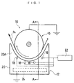
- Fig. 1 is a side view of assistance in explaining the first embodiment of a web charging apparatus according to the present invention.
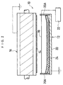
- Fig. 2 is a front sectional view taken along the line A-A of Fig. 1.
- the web charging apparatus 10 comprises a discharge electrode device 12 and a first grounded electrode or a roller 16 that is grounded and provided above the discharge electrode device 12.
- the roller 16 serves both as a counter electrode for corona discharge and a supporting roller for a moving web 14.
- the discharge electrode device 12 includes discharge electrodes or wire electrodes 18, which are supported in tension between side plates 20A of an electrode supporting frame 20 and are parallel to the axis of the roller 16.
- a plurality of (e.g. four) wire electrodes 18 are arranged in parallel to each other at regular intervals on a circle concentric with the roller 16, in other words, the wire electrodes 18 are arranged along the path of the web 14.
- the wire electrodes 18 are made from a conductive material, e.g. tungsten, molybdenum, platinum, and carbon fiber, and preferably have a diameter of about 100 ⁇ m to about 200 ⁇ m.
- Each side plate 20A of the electrode supporting frame 20 is provided with stretchers (not shown), each of which supports an end of one of the wire electrodes 18 and can adjust a tensile force of the wire electrode 18.
- the wire electrodes 18 are preferably stretched under a tensile force of about 10N.
- each side plate 20A has a curve along the periphery of the roller 16.
- the web 14 moves over the roller 16 while being in contact with the outer surface of the roller 16, which is grounded to function as the counter electrode.
- the distance between each wire electrode 18 and the web 14 supported on the roller 16 is about 10mm.
- the wire electrodes 18 are connected to a source 22 of direct voltage of about 6500V, and the corona discharge is established between the wire electrodes 18 and the roller 16 via the web 14.
- a second grounded electrode or a grounded plate 24 is arranged behind the wire electrodes 18 relative to the roller 16.
- the grounded plate 24 is grounded and is a rectangle whose length is substantially equal to the length of the wire electrodes 18 and whose width is substantially equal to the diameter of the roller 16.
- both lengthwise (widthwise of the web 14) end parts of the grounded plate 24, that is, the parts facing to the edge parts of the web 14 supported on the roller 16 are bent to be closer to the web 14.
- the grounded plate 24 is made from a metal, e.g. aluminum, copper, iron, and stainless steal, or a nonmetallic conductor.
- the web 14 passes through the web charging apparatus 10, and then, it reaches a coating apparatus 26.
- the source 22 applies a high voltage to the wire electrodes 18 so that the corona discharge is established between the wire electrodes 18 and the roller 16 via the web 14. Thereby, unipolar electrostatic charges are deposited on the surface of the web 14.
- the web 14 passes a surface electrometer 28, which measures and records a surface electrostatic potential on the web 14, and reaches the coating apparatus 26 via a pass roller 30.
- a coating head 34 of the coating apparatus 26 applies a coating solution 36 to the surface of the web 14 supported on a backup roller 32.
- the web 14 is coated with the coating solution 36.
- the web charging apparatus 10 deposits the unipolar electrostatic charges on the surface of the web 14, thereby improving the affinity and adhesion of the coating solution 36 to the web 14.
- the coating performance can be improved.
- a conventional web charging apparatus has the problem of the "liquid exhaustion at the edge parts of the web" in that the edge parts of the web cannot satisfactorily be coated with the coating solution, since the electrostatic potential at the edge parts of the web is lower than the electrostatic potential at the central part of the web.
- the web charging apparatus 10 is provided with the grounded plate 24 behind the wire electrodes 18 relative to the roller 16.
- the grounded plate 24 By bending the lengthwise ends of the grounded plate 24 toward the web 14, it is easy to equalize the electrostatic potential at the edge parts and the central part of the web 14. Even if they are not bent, a satisfactory effect can also be achieved.
- the grounded plate 24 is provided behind the wire electrodes 18 relative to the roller 16, thereby equalizing the electrostatic potential at the edge parts and the central part of the web 14. That is because the intensity of the electrostatic field that is formed in the space between the wire electrodes 18 and the roller 16, is uniform over the whole width of the web 14. Thus, it is possible to prevent the "liquid exhaustion at the edge parts of the web" by providing the grounded plate 24.
- the web charging apparatus 10 there is no necessity to finely adjust the distance between each wire electrode 18 and the web 14 by less than 1mm, unlike the conventional web charging apparatus. It is also possible to prevent the sag of the wire electrodes 18 from affecting the electrostatic potential on the web 14, thereby equalizing the electrostatic potential at the edge parts and the central part of the web 14.
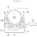
- Fig. 4 is a side view of assistance in explaining the second embodiment of the web charging apparatus 10 according to the present invention, and parts similar to those of the first embodiment will be denoted by the same reference numerals.
- the grounded plate 24 is curved along the periphery of the roller 16. Thereby, the distances between the grounded plate 24 and the wire electrodes 18, which are arranged in parallel at regular intervals along the path of the web 14, can be uniform.
- the intensity of the electrostatic field that is formed between the wire electrodes 18 and the web 14 can also be uniform in the direction in which the web 14 moves. Thus, it is possible to avoid a change in the electrostatic potential in the direction in which the web 14 moves, so that the web 14 can be uniformly coated in its moving direction.
- Fig. 5 is a side view of assistance in explaining the third embodiment of the web charging apparatus 10 according to the present invention, and parts similar to those of the first embodiment will be denoted by the same reference numerals.
- the central part of the grounded plate 24 is curved along the periphery of the roller 16, and both widthwise end parts of the grounded plate 24 are bent toward the roller 16 in a manner to enclose the wire electrodes 18.
- the third embodiment can achieve the same effects as the second embodiment, and besides, the wire electrodes 18 are enclosed by the grounded plate 24 to prevent the disturbance. Thus, the electrostatic field can be more stable.
- Fig. 6 is a front sectional view of assistance in explaining the fourth embodiment of the web charging apparatus 10 according to the present invention, and parts similar to those of the first embodiment will be denoted by the same reference numerals.
- the grounded plate 24 is separated into three grounded plates 24A and 24B.
- the grounded plate 24A is arranged to face the central part of the web 14, and the grounded plates 24B are arranged to face both edge parts of the web 14.
- Each of the grounded plates 24A and 24B is movable in the vertical direction in Fig. 6.
- the grounded plate 24 there is no necessity to bend both lengthwise ends of the grounded plate 24. Moreover, it is possible to adjust the distances between the web 14 and the grounded plates 24B and between the web 14 and the grounded plate 24A independently of one another. Thus, it is possible to equalize the electrostatic potential at the edge parts and the central part of the web 14, or to intentionally make the electrostatic potential at the edge parts of the web 14 lower than the electrostatic potential at the central part of the web 14 to thereby decrease the coating solution applied on the edge parts of the web 14.
- the grounded plate 24A facing the central part of the web 14 may be removed, so that the only grounded plates 24B are arranged to face the edge parts of the web 14.
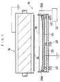
- Fig. 7 is a front sectional view of assistance in explaining the fifth embodiment of the web charging apparatus 10 according to the present invention, and parts similar to those of the first embodiment will be denoted by the same reference numerals.
- the grounded plate 24 is provided with a distance adjusting device or bolts 40 that adjust the distance between the grounded plate 24 and the wire electrodes 18.
- the ends of the bolts 40 which engage with a bottom plate of the electrode support frame 20, are in contact with the central part and the lengthwise end parts of the grounded plate 24.
- a material that elastically deforms easily is suitable for the grounded plate 24.
- the bolts 40 are pressed against the grounded plate 24, so that the distance between the grounded plate 24 and the web 14 can be finely adjusted so as to equalize the electrostatic potential at the edge parts and the central part of the web 14.
- the distance adjusting device for the grounded plate 24 are not restricted to the bolts 40, but air cylinders, etc. may be used.
- the number of the bolts 40 is not restricted to three.
- the first grounded electrode 16 functions as the supporting roller for the web 14, but the present invention should not be restricted to this.
- the first grounded electrode 16 may be an unrotative cylinder, a rod, a pipe, a plate, or a moving belt.
- the discharge electrode 18 should not be restricted to the wire, but may be a bristle blush.
- the number of the discharge electrode 18 may be one.
- the second grounded electrode 24 should not be necessarily the rectangular plate.
- the second grounded electrode 24 may be any shape that does not disturb the electrostatic field between the wire electrodes 18 and the web 14.
- the second grounded electrode 24 may be a plane as in the first embodiment and an arc as in the second embodiment.
- the second grounded electrode 24 may be a wire, a rod, a belt, or a grid.
- a web as the web 14 was made of TAC (triacetyl cellulose), coated with gelatin, 200mm in width, and ordinarily used for a photographic film.
- the web 14 was transported at a speed of 100m/min.
- four wires as the wire electrodes 18 were made of tungsten, 100 ⁇ m in diameter, and 200mm in length.
- the wire electrodes 18 were arranged in parallel so that each distance to the web 14 was 10mm.
- An aluminum plate was used as the grounded plate 24.
- the power supply 22 applied a direct voltage of 6300V to the wire electrodes 18, so that the corona discharge was established between the wire electrodes 18 and the web 14. Thereby, the unipolar electrostatic charges were deposited on the surface of the web 14. Then, the surface electrometer 28 measured the electrostatic potential on the charged surface of the web 14. After the measurement, the coating apparatus 26 applied the coating solution 36 on the web 14.
- the surface electrostatic potential on the web 14 was measured at the central part and the edge part, specifically, the point positioned inside by 20mm from the widthwise end of the web 14.
- the measurement was also performed in the case where no grounded plate was provided.
- the surface electrostatic potential ratio was approximately 1 when the grounded plate 24 was provided, whereas the ratio was 0.42 when the grounded plate 24 was not provided. There may be some fluctuations in the ratios according to conditions such as the shape of the grounded plate 24 and the voltage applied to the wire electrodes 18.
- the surface electrostatic potential ratio was 1, and the electrostatic potential at the edge parts and the central part of the web 14 was perfectly uniform. Thus, it was proved that it is possible to uniformly deposit the unipolar electrostatic charges on the whole width of the web 14 by providing the grounded plate 24.
- the unipolar electrostatic charges can be uniformly deposited on the whole width of the web, and thus, it is possible to equalize the affinity and adhesion of the coating solution applied on the edge parts and the central part of the web.
- the coating apparatus utilizing the web charging apparatus according to the present invention can intentionally coat the edge parts of the web thicker than the central part.
Landscapes
- Physics & Mathematics (AREA)
- Engineering & Computer Science (AREA)
- Plasma & Fusion (AREA)
- Coating Apparatus (AREA)
- Application Of Or Painting With Fluid Materials (AREA)
- Shaping Of Tube Ends By Bending Or Straightening (AREA)
- Fixing For Electrophotography (AREA)
- Charge And Discharge Circuits For Batteries Or The Like (AREA)
- Elimination Of Static Electricity (AREA)
Priority Applications (2)
| Application Number | Priority Date | Filing Date | Title |
|---|---|---|---|
| EP04017014A EP1465306A3 (de) | 1997-05-13 | 1998-05-11 | Vorrichtung zur elektrischen Aufladung eines bahnförmigen Substrats. |
| EP04017013A EP1465305A3 (de) | 1997-05-13 | 1998-05-11 | Vorrichtung zur elektrischen Aufladung eines bahnförmigen Substrats |
Applications Claiming Priority (3)
| Application Number | Priority Date | Filing Date | Title |
|---|---|---|---|
| JP122621/97 | 1997-05-13 | ||
| JP12262197A JP3944889B2 (ja) | 1997-05-13 | 1997-05-13 | ウエブ帯電用装置 |
| JP12262197 | 1997-05-13 |
Related Child Applications (2)
| Application Number | Title | Priority Date | Filing Date |
|---|---|---|---|
| EP04017013A Division EP1465305A3 (de) | 1997-05-13 | 1998-05-11 | Vorrichtung zur elektrischen Aufladung eines bahnförmigen Substrats |
| EP04017014A Division EP1465306A3 (de) | 1997-05-13 | 1998-05-11 | Vorrichtung zur elektrischen Aufladung eines bahnförmigen Substrats. |
Publications (2)
| Publication Number | Publication Date |
|---|---|
| EP0878885A1 true EP0878885A1 (de) | 1998-11-18 |
| EP0878885B1 EP0878885B1 (de) | 2004-07-28 |
Family
ID=14840503
Family Applications (3)
| Application Number | Title | Priority Date | Filing Date |
|---|---|---|---|
| EP04017014A Withdrawn EP1465306A3 (de) | 1997-05-13 | 1998-05-11 | Vorrichtung zur elektrischen Aufladung eines bahnförmigen Substrats. |
| EP04017013A Withdrawn EP1465305A3 (de) | 1997-05-13 | 1998-05-11 | Vorrichtung zur elektrischen Aufladung eines bahnförmigen Substrats |
| EP98108556A Expired - Lifetime EP0878885B1 (de) | 1997-05-13 | 1998-05-11 | Vorrichtung zur elektrischen Aufladung eines bahnförmigen Substrats |
Family Applications Before (2)
| Application Number | Title | Priority Date | Filing Date |
|---|---|---|---|
| EP04017014A Withdrawn EP1465306A3 (de) | 1997-05-13 | 1998-05-11 | Vorrichtung zur elektrischen Aufladung eines bahnförmigen Substrats. |
| EP04017013A Withdrawn EP1465305A3 (de) | 1997-05-13 | 1998-05-11 | Vorrichtung zur elektrischen Aufladung eines bahnförmigen Substrats |
Country Status (5)
| Country | Link |
|---|---|
| US (1) | US6086675A (de) |
| EP (3) | EP1465306A3 (de) |
| JP (1) | JP3944889B2 (de) |
| AT (1) | ATE272261T1 (de) |
| DE (1) | DE69825210T2 (de) |
Families Citing this family (6)
| Publication number | Priority date | Publication date | Assignee | Title |
|---|---|---|---|---|
| US6436191B1 (en) * | 1997-12-01 | 2002-08-20 | Eastman Kodak Company | Corona discharge treatment roller and surface finishing process |
| US7339778B1 (en) * | 2003-06-11 | 2008-03-04 | Ion Systems | Corona discharge static neutralizing apparatus |
| US7483255B2 (en) * | 2003-06-11 | 2009-01-27 | Ion Systems | Ionizing electrode structure and apparatus |
| DE102009058208A1 (de) * | 2009-12-15 | 2011-06-16 | Eisenmann Anlagenbau Gmbh & Co. Kg | Verfahren und Vorrichtung zum Abscheiden von Overspray sowie Anlage mit einer solchen |
| JP6543992B2 (ja) * | 2015-03-26 | 2019-07-17 | 富士ゼロックス株式会社 | 粉体塗装装置、及び粉体塗装方法 |
| CN110039756A (zh) * | 2019-03-26 | 2019-07-23 | 宁波太古新材料科技有限公司 | 一种智能化保护膜电晕处理装置 |
Citations (7)
| Publication number | Priority date | Publication date | Assignee | Title |
|---|---|---|---|---|
| US3390266A (en) * | 1964-11-05 | 1968-06-25 | Epping Reinhold Hermann | Apparatus for charging the surface of photoelectric layers using corona discharge |
| FR2073907A5 (de) * | 1969-12-17 | 1971-10-01 | Kalle Ag | |
| US3612864A (en) * | 1968-01-13 | 1971-10-12 | Yasuo Tamai | Imaging system utilizing an electrode treated with a mixture of a hygroscopic material and a hydrophilic binder |
| US3783283A (en) * | 1972-09-26 | 1974-01-01 | Sperry Rand Corp | Corona charging device with semiconductive shield |
| US4486808A (en) * | 1982-12-03 | 1984-12-04 | Polaroid Corporation | Apparatus for controlling random charges on a moving web |
| US5018045A (en) * | 1989-04-14 | 1991-05-21 | Minolta Camera Kabushiki Kaisha | Corona discharger for use in electrophotographic copying machine |
| US5138971A (en) * | 1990-07-03 | 1992-08-18 | Fuji Photo Film Co., Ltd. | Web charging apparatus |
Family Cites Families (5)
| Publication number | Priority date | Publication date | Assignee | Title |
|---|---|---|---|---|
| US3937960A (en) * | 1972-02-22 | 1976-02-10 | Rank Xerox, Ltd. | Charging device for electrophotography |
| US4322156A (en) * | 1979-08-14 | 1982-03-30 | Tokyo Shibaura Denki Kabushiki Kaisha | Charging apparatus for copying machine |
| JPS5664359A (en) * | 1979-10-31 | 1981-06-01 | Toshiba Corp | Charging device in electrophotographic copying machine |
| JP3207877B2 (ja) * | 1991-07-22 | 2001-09-10 | 株式会社日立製作所 | 静電記録装置 |
| DE69701060T2 (de) * | 1992-06-04 | 2000-06-08 | Sharp K.K., Osaka | Ladegerät |
-
1997
- 1997-05-13 JP JP12262197A patent/JP3944889B2/ja not_active Expired - Fee Related
-
1998
- 1998-05-08 US US09/074,387 patent/US6086675A/en not_active Expired - Fee Related
- 1998-05-11 DE DE1998625210 patent/DE69825210T2/de not_active Expired - Lifetime
- 1998-05-11 AT AT98108556T patent/ATE272261T1/de not_active IP Right Cessation
- 1998-05-11 EP EP04017014A patent/EP1465306A3/de not_active Withdrawn
- 1998-05-11 EP EP04017013A patent/EP1465305A3/de not_active Withdrawn
- 1998-05-11 EP EP98108556A patent/EP0878885B1/de not_active Expired - Lifetime
Patent Citations (7)
| Publication number | Priority date | Publication date | Assignee | Title |
|---|---|---|---|---|
| US3390266A (en) * | 1964-11-05 | 1968-06-25 | Epping Reinhold Hermann | Apparatus for charging the surface of photoelectric layers using corona discharge |
| US3612864A (en) * | 1968-01-13 | 1971-10-12 | Yasuo Tamai | Imaging system utilizing an electrode treated with a mixture of a hygroscopic material and a hydrophilic binder |
| FR2073907A5 (de) * | 1969-12-17 | 1971-10-01 | Kalle Ag | |
| US3783283A (en) * | 1972-09-26 | 1974-01-01 | Sperry Rand Corp | Corona charging device with semiconductive shield |
| US4486808A (en) * | 1982-12-03 | 1984-12-04 | Polaroid Corporation | Apparatus for controlling random charges on a moving web |
| US5018045A (en) * | 1989-04-14 | 1991-05-21 | Minolta Camera Kabushiki Kaisha | Corona discharger for use in electrophotographic copying machine |
| US5138971A (en) * | 1990-07-03 | 1992-08-18 | Fuji Photo Film Co., Ltd. | Web charging apparatus |
Also Published As
| Publication number | Publication date |
|---|---|
| JPH10312878A (ja) | 1998-11-24 |
| EP1465305A2 (de) | 2004-10-06 |
| EP0878885B1 (de) | 2004-07-28 |
| JP3944889B2 (ja) | 2007-07-18 |
| EP1465306A3 (de) | 2005-03-30 |
| DE69825210T2 (de) | 2004-11-18 |
| US6086675A (en) | 2000-07-11 |
| DE69825210D1 (de) | 2004-09-02 |
| EP1465306A2 (de) | 2004-10-06 |
| EP1465305A3 (de) | 2005-03-30 |
| ATE272261T1 (de) | 2004-08-15 |
Similar Documents
| Publication | Publication Date | Title |
|---|---|---|
| US5138971A (en) | Web charging apparatus | |
| US5414500A (en) | Image recording apparatus | |
| US4984024A (en) | Image transfer unit for image recording apparatus | |
| EP0878885B1 (de) | Vorrichtung zur elektrischen Aufladung eines bahnförmigen Substrats | |
| US6146805A (en) | Printing method, printer, printed object, and optical disk | |
| US5295039A (en) | Method of applying single polar electro-static charges to continuously travelling long web support, and apparatus practicing same | |
| CA1282107C (en) | Flat comb-like scorotron charging device | |
| JPS62503200A (ja) | 静電荷除去装置 | |
| JP2000019854A (ja) | 画像形成装置 | |
| US4527177A (en) | Ion projection printer with virtual back electrode | |
| US5988794A (en) | Aperture electrode assembly for an image forming device | |
| JP3315218B2 (ja) | 画像形成装置 | |
| JPH04233561A (ja) | 静電印刷装置の帯電装置 | |
| JPH05134590A (ja) | 圧力定着方式の画像記録装置 | |
| JPH01288879A (ja) | 転写型画像形成装置 | |
| JPH01257873A (ja) | 交流コロナ放電装置 | |
| JPH01288880A (ja) | 転写ローラ機構 | |
| JP3276774B2 (ja) | 記録装置 | |
| JPS63315437A (ja) | 転写材送り装置 | |
| JPH0740577A (ja) | 画像形成装置 | |
| JPH0789119A (ja) | 画像形成装置 | |
| JPH07108706A (ja) | 画像形成装置 | |
| JPH03230969A (ja) | 静電記録装置 | |
| JPH06286203A (ja) | 記録用電極 | |
| JPH04162053A (ja) | 画像記録装置 |
Legal Events
| Date | Code | Title | Description |
|---|---|---|---|
| PUAI | Public reference made under article 153(3) epc to a published international application that has entered the european phase |
Free format text: ORIGINAL CODE: 0009012 |
|
| AK | Designated contracting states |
Kind code of ref document: A1 Designated state(s): AT BE CH CY DE DK ES FI FR GB GR IE IT LI LU MC NL PT SE |
|
| AX | Request for extension of the european patent |
Free format text: AL;LT;LV;MK;RO;SI |
|
| 17P | Request for examination filed |
Effective date: 19990330 |
|
| AKX | Designation fees paid |
Free format text: AT BE CH CY DE DK ES FI FR GB GR IE IT LI LU MC NL PT SE |
|
| 17Q | First examination report despatched |
Effective date: 20020917 |
|
| GRAP | Despatch of communication of intention to grant a patent |
Free format text: ORIGINAL CODE: EPIDOSNIGR1 |
|
| GRAS | Grant fee paid |
Free format text: ORIGINAL CODE: EPIDOSNIGR3 |
|
| GRAA | (expected) grant |
Free format text: ORIGINAL CODE: 0009210 |
|
| AK | Designated contracting states |
Kind code of ref document: B1 Designated state(s): AT BE CH CY DE DK ES FI FR GB GR IE IT LI LU MC NL PT SE |
|
| PG25 | Lapsed in a contracting state [announced via postgrant information from national office to epo] |
Ref country code: NL Free format text: LAPSE BECAUSE OF FAILURE TO SUBMIT A TRANSLATION OF THE DESCRIPTION OR TO PAY THE FEE WITHIN THE PRESCRIBED TIME-LIMIT Effective date: 20040728 Ref country code: LI Free format text: LAPSE BECAUSE OF FAILURE TO SUBMIT A TRANSLATION OF THE DESCRIPTION OR TO PAY THE FEE WITHIN THE PRESCRIBED TIME-LIMIT Effective date: 20040728 Ref country code: IT Free format text: LAPSE BECAUSE OF FAILURE TO SUBMIT A TRANSLATION OF THE DESCRIPTION OR TO PAY THE FEE WITHIN THE PRESCRIBED TIME-LIMIT;WARNING: LAPSES OF ITALIAN PATENTS WITH EFFECTIVE DATE BEFORE 2007 MAY HAVE OCCURRED AT ANY TIME BEFORE 2007. THE CORRECT EFFECTIVE DATE MAY BE DIFFERENT FROM THE ONE RECORDED. Effective date: 20040728 Ref country code: FR Free format text: LAPSE BECAUSE OF FAILURE TO SUBMIT A TRANSLATION OF THE DESCRIPTION OR TO PAY THE FEE WITHIN THE PRESCRIBED TIME-LIMIT Effective date: 20040728 Ref country code: FI Free format text: LAPSE BECAUSE OF FAILURE TO SUBMIT A TRANSLATION OF THE DESCRIPTION OR TO PAY THE FEE WITHIN THE PRESCRIBED TIME-LIMIT Effective date: 20040728 Ref country code: CH Free format text: LAPSE BECAUSE OF FAILURE TO SUBMIT A TRANSLATION OF THE DESCRIPTION OR TO PAY THE FEE WITHIN THE PRESCRIBED TIME-LIMIT Effective date: 20040728 Ref country code: BE Free format text: LAPSE BECAUSE OF FAILURE TO SUBMIT A TRANSLATION OF THE DESCRIPTION OR TO PAY THE FEE WITHIN THE PRESCRIBED TIME-LIMIT Effective date: 20040728 Ref country code: AT Free format text: LAPSE BECAUSE OF FAILURE TO SUBMIT A TRANSLATION OF THE DESCRIPTION OR TO PAY THE FEE WITHIN THE PRESCRIBED TIME-LIMIT Effective date: 20040728 |
|
| REG | Reference to a national code |
Ref country code: GB Ref legal event code: FG4D |
|
| REG | Reference to a national code |
Ref country code: CH Ref legal event code: EP |
|
| REG | Reference to a national code |
Ref country code: IE Ref legal event code: FG4D |
|
| REF | Corresponds to: |
Ref document number: 69825210 Country of ref document: DE Date of ref document: 20040902 Kind code of ref document: P |
|
| PG25 | Lapsed in a contracting state [announced via postgrant information from national office to epo] |
Ref country code: SE Free format text: LAPSE BECAUSE OF FAILURE TO SUBMIT A TRANSLATION OF THE DESCRIPTION OR TO PAY THE FEE WITHIN THE PRESCRIBED TIME-LIMIT Effective date: 20041028 Ref country code: GR Free format text: LAPSE BECAUSE OF FAILURE TO SUBMIT A TRANSLATION OF THE DESCRIPTION OR TO PAY THE FEE WITHIN THE PRESCRIBED TIME-LIMIT Effective date: 20041028 Ref country code: DK Free format text: LAPSE BECAUSE OF FAILURE TO SUBMIT A TRANSLATION OF THE DESCRIPTION OR TO PAY THE FEE WITHIN THE PRESCRIBED TIME-LIMIT Effective date: 20041028 |
|
| PG25 | Lapsed in a contracting state [announced via postgrant information from national office to epo] |
Ref country code: ES Free format text: LAPSE BECAUSE OF FAILURE TO SUBMIT A TRANSLATION OF THE DESCRIPTION OR TO PAY THE FEE WITHIN THE PRESCRIBED TIME-LIMIT Effective date: 20041108 |
|
| NLV1 | Nl: lapsed or annulled due to failure to fulfill the requirements of art. 29p and 29m of the patents act | ||
| REG | Reference to a national code |
Ref country code: CH Ref legal event code: PL |
|
| PG25 | Lapsed in a contracting state [announced via postgrant information from national office to epo] |
Ref country code: LU Free format text: LAPSE BECAUSE OF NON-PAYMENT OF DUE FEES Effective date: 20050511 Ref country code: IE Free format text: LAPSE BECAUSE OF NON-PAYMENT OF DUE FEES Effective date: 20050511 Ref country code: GB Free format text: LAPSE BECAUSE OF NON-PAYMENT OF DUE FEES Effective date: 20050511 Ref country code: CY Free format text: LAPSE BECAUSE OF FAILURE TO SUBMIT A TRANSLATION OF THE DESCRIPTION OR TO PAY THE FEE WITHIN THE PRESCRIBED TIME-LIMIT Effective date: 20050511 |
|
| PG25 | Lapsed in a contracting state [announced via postgrant information from national office to epo] |
Ref country code: MC Free format text: LAPSE BECAUSE OF NON-PAYMENT OF DUE FEES Effective date: 20050531 |
|
| PLBE | No opposition filed within time limit |
Free format text: ORIGINAL CODE: 0009261 |
|
| STAA | Information on the status of an ep patent application or granted ep patent |
Free format text: STATUS: NO OPPOSITION FILED WITHIN TIME LIMIT |
|
| 26N | No opposition filed |
Effective date: 20050429 |
|
| EN | Fr: translation not filed | ||
| GBPC | Gb: european patent ceased through non-payment of renewal fee |
Effective date: 20050511 |
|
| REG | Reference to a national code |
Ref country code: IE Ref legal event code: MM4A |
|
| PG25 | Lapsed in a contracting state [announced via postgrant information from national office to epo] |
Ref country code: PT Free format text: LAPSE BECAUSE OF NON-PAYMENT OF DUE FEES Effective date: 20041228 |
|
| PGFP | Annual fee paid to national office [announced via postgrant information from national office to epo] |
Ref country code: DE Payment date: 20100415 Year of fee payment: 13 |
|
| REG | Reference to a national code |
Ref country code: DE Ref legal event code: R119 Ref document number: 69825210 Country of ref document: DE |
|
| REG | Reference to a national code |
Ref country code: DE Ref legal event code: R119 Ref document number: 69825210 Country of ref document: DE |
|
| PG25 | Lapsed in a contracting state [announced via postgrant information from national office to epo] |
Ref country code: DE Free format text: LAPSE BECAUSE OF NON-PAYMENT OF DUE FEES Effective date: 20111130 |