EP0878899A1 - Linearmotor mit leichtem montierbaren Stator - Google Patents
Linearmotor mit leichtem montierbaren Stator Download PDFInfo
- Publication number
- EP0878899A1 EP0878899A1 EP98108643A EP98108643A EP0878899A1 EP 0878899 A1 EP0878899 A1 EP 0878899A1 EP 98108643 A EP98108643 A EP 98108643A EP 98108643 A EP98108643 A EP 98108643A EP 0878899 A1 EP0878899 A1 EP 0878899A1
- Authority
- EP
- European Patent Office
- Prior art keywords
- permanent magnets
- stator
- linear motor
- screw portion
- center shaft
- Prior art date
- Legal status (The legal status is an assumption and is not a legal conclusion. Google has not performed a legal analysis and makes no representation as to the accuracy of the status listed.)
- Pending
Links
- 239000000696 magnetic material Substances 0.000 claims abstract description 11
- 239000000463 material Substances 0.000 claims description 4
- 229910052761 rare earth metal Inorganic materials 0.000 claims description 2
- 150000002910 rare earth metals Chemical class 0.000 claims description 2
- 229910000859 α-Fe Inorganic materials 0.000 claims description 2
- 230000004907 flux Effects 0.000 description 7
- 239000000853 adhesive Substances 0.000 description 6
- 230000001070 adhesive effect Effects 0.000 description 6
- 238000000034 method Methods 0.000 description 4
- 238000005259 measurement Methods 0.000 description 3
- 229910001220 stainless steel Inorganic materials 0.000 description 3
- 239000010935 stainless steel Substances 0.000 description 3
- 238000010276 construction Methods 0.000 description 2
- 238000004519 manufacturing process Methods 0.000 description 2
- 229910001369 Brass Inorganic materials 0.000 description 1
- XAGFODPZIPBFFR-UHFFFAOYSA-N aluminium Chemical compound [Al] XAGFODPZIPBFFR-UHFFFAOYSA-N 0.000 description 1
- 229910052782 aluminium Inorganic materials 0.000 description 1
- 239000010951 brass Substances 0.000 description 1
- 230000000694 effects Effects 0.000 description 1
- 230000003993 interaction Effects 0.000 description 1
- 238000003801 milling Methods 0.000 description 1
Images


Classifications
-
- H—ELECTRICITY
- H02—GENERATION; CONVERSION OR DISTRIBUTION OF ELECTRIC POWER
- H02K—DYNAMO-ELECTRIC MACHINES
- H02K41/00—Propulsion systems in which a rigid body is moved along a path due to dynamo-electric interaction between the body and a magnetic field travelling along the path
- H02K41/02—Linear motors; Sectional motors
- H02K41/03—Synchronous motors; Motors moving step by step; Reluctance motors
- H02K41/031—Synchronous motors; Motors moving step by step; Reluctance motors of the permanent magnet type
Definitions
- the present invention relates to a linear motor, particularly to an improvement in a stator which is constructed by combining a plurality of permanent magnets.
- the linear motor has a stator in which a plurality of permanent magnets are combined in series so that their opposite magnetic poles may face to each other, and a movable part which is disposed outside the stator so as to surround the stator and which includes a coil capable of sliding in the axial direction of the stator.
- a stator in which a plurality of permanent magnets are combined in series so that their opposite magnetic poles may face to each other
- a movable part which is disposed outside the stator so as to surround the stator and which includes a coil capable of sliding in the axial direction of the stator.
- the positioning accuracy of the movable part is affected by the assembling accuracy of the plurality of permanent magnets in the stator.
- the plurality of permanent magnets are fixed to a bar-shaped supporting member by adhesion as described later in detail.
- a linear motor according to the present invention includes a stator which is constructed by assembling a plurality of permanent magnets in series so that their opposite magnetic poles may face to each other.
- each permanent magnet has a cylindrical base shape.
- the stator includes a center shaft of non-magnetic material inserted in the plurality of permanent magnets.
- the plurality of permanent magnets are tightened from both sides thereof so that the adjacent permanent magnets may be close to each other.
- a stator 1 in a prior art linear motor will be described with reference to Fig. 1.
- a stator 1 includes a bar-shaped supporting member 2 made of non-magnetic material and block-shaped permanent magnets 3.
- the permanent magnets 3 are disposed in series on both sides of the supporting member 2 and mounted to each other with adhesion so that their opposite magnetic poles face to each other.
- the length of each permanent magnet 3 is in the extent of several cm.
- the length of the stator 1 is less than 1 m. Therefore, more than scores of permanent magnets 3 must be adhered to the supporting member 2.
- a linear motor according to this embodiment includes a stator 10 and a movable part 20.
- the stator 10 includes a bracket 11 made of non-magnetic material and a pipe 12 made of non-magnetic material and including a large number of permanent magnets, as described later in detail.
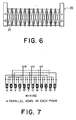
- the movable part 20 has coils (here, twelve coils) 21 as shown in Fig. 6.
- the pipe 12 penetrates those coils 21.
- the movable part 20 can slide in the axial direction of the pipe 12 in contact or non-contact with the pipe 12.
- a three-phase alternating current source is connected to the twelve coils 21 and the coils 21 are connected to the phases W, U and V as shown in Fig. 7.
- the stator 10 which is the most characteristic part in the present invention, will be described with reference to Fig. 5.
- the stator 10 has cylindrical or ring-shaped permanent magnets 13, a center shaft 14 inserted in the permanent magnets 13, and a nut 15 for tightening in addition to the bracket 11 and the pipe 12.
- a male screw portion 14-1 is provided on one end portion of the center shaft 14.
- the male screw portion 14-1 is relatively screwed in a female screw portion provided in the bracket 11.
- Another male portion 14-2 having a predetermined length is provided on the other end side of the center shaft 14.
- the nut 15 is engaged with the male portion 14-2 so that the permanent magnets 13 are brought into close contact with each other between the bracket 11 and the nut 15.
- the permanent magnets 13 are disposed in series so that those opposite magnetic poles face to each other.
- the pipe 12 having a circular cross-section covers the outer peripheries of the permanent magnets 13.
- the bracket 11 is provided with holes 11-1 for inserting screws to mount the stator 10 to an apparatus in which this linear motor is equipped.
- the permanent magnets 13 rare-earth material or ferrite material having large magnetic flux density is preferable, but other magnetic material may be used.
- any of non-magnetic materials such as aluminum, brass and stainless steel can be used.
- the center shaft 14 non-magnetic material such as stainless steel is used.
- the center shaft 14 is designed to obtain sufficient mechanical strength for assembling the permanent magnets 13.
- the pipe 12 is as thin as possible so as not to decrease the magnetic field acting on the movable part 20 which is disposed outside the pipe 12.
- the pipe 12 is made of stainless steel of 1 mm thickness.
- the pipe 12 has an inside diameter to be in close contact with the outer peripheries of the permanent magnets 13. The pipe 12 thus prevents the permanent magnets 13 from being rusted.
- the pipe 12 serves as a guide for the movable part 20 if the movable part 20 is slid in contact with the pipe 12.
- the male screw portion 14-1 of the center shaft 14 is relatively screwed in the female screw portion of the bracket 11.
- the pipe 12 is disposed around the center shaft 14 and the permanent magnets 13 are put on the center shaft 14 one by one and inserted in the pipe 12.
- the nut 15 is engaged with the male screw portion 14-2 and the permanent magnets 13 are tightened so that the adjacent permanent magnets 13 may be close to each other.
- the nut 15 In the case of the pipe 12 having a length longer than the total length of the predetermined number of the assembled permanent magnets 13 as shown in Fig. 5, the nut 15 must be turned in the pipe 12. In that case, the nut 15 can be turned with a specific jig.
- the opening of the pipe 12 is closed with a cap 16.
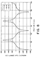
- a measurement result of the magnetic flux density around the stator 10 is shown in Fig. 8.
- each permanent magnet 13 is not limited to ring but may be polygonal. In any case, the pipe 12 must have the cross-sectional shape corresponding to that of each permanent magnet 13.
- Application of the linear motor according to the present invention is not limited to a relatively small-sized apparatus such as an office automation apparatus but the linear motor according to the present invention can also be applied to a part having need of linear movement in a large-sized industrial machine, for instance, to a transfer table in a large-sized machine tool such as a milling machine.
Landscapes
- Engineering & Computer Science (AREA)
- Physics & Mathematics (AREA)
- Chemical & Material Sciences (AREA)
- Combustion & Propulsion (AREA)
- Electromagnetism (AREA)
- Power Engineering (AREA)
- Linear Motors (AREA)
Applications Claiming Priority (2)
| Application Number | Priority Date | Filing Date | Title |
|---|---|---|---|
| JP120830/97 | 1997-05-12 | ||
| JP9120830A JPH10313566A (ja) | 1997-05-12 | 1997-05-12 | リニアモータ |
Publications (1)
| Publication Number | Publication Date |
|---|---|
| EP0878899A1 true EP0878899A1 (de) | 1998-11-18 |
Family
ID=14796026
Family Applications (1)
| Application Number | Title | Priority Date | Filing Date |
|---|---|---|---|
| EP98108643A Pending EP0878899A1 (de) | 1997-05-12 | 1998-05-12 | Linearmotor mit leichtem montierbaren Stator |
Country Status (3)
| Country | Link |
|---|---|
| US (1) | US6040642A (de) |
| EP (1) | EP0878899A1 (de) |
| JP (1) | JPH10313566A (de) |
Cited By (4)
| Publication number | Priority date | Publication date | Assignee | Title |
|---|---|---|---|---|
| DE19853250A1 (de) * | 1998-11-18 | 2000-05-25 | Siemens Linear Motor Systems G | Linearmotor und Sekundärteil für einen Linearmotor |
| US6313551B1 (en) | 2000-02-04 | 2001-11-06 | Nikon Corporation | Magnet array for a shaft-type linear motor |
| WO2004071793A1 (de) * | 2003-02-17 | 2004-08-26 | Bayerische Motoren Werke | Aktive fahrzeug-radaufhängung mit einem linearmotor |
| WO2005085780A1 (de) | 2004-03-01 | 2005-09-15 | Applied Materials Gmbh & Co. Kg | Substrat mit einem fabry-perot-filter und verfahren zum aufbringen des filters auf das substrat |
Families Citing this family (44)
| Publication number | Priority date | Publication date | Assignee | Title |
|---|---|---|---|---|
| GB2343997B (en) * | 1998-11-23 | 2003-06-25 | Linear Drives Ltd | Coaxial linear motor for extended travel |
| US6323567B1 (en) | 1999-12-24 | 2001-11-27 | Nikon Corporation | Circulating system for shaft-type linear motors |
| JP4527826B2 (ja) * | 2000-01-28 | 2010-08-18 | Thk株式会社 | 高推力リニアモータ及びその製造方法 |
| JP3470293B2 (ja) * | 2001-12-17 | 2003-11-25 | 山崎 恒彦 | リニアモータ |
| ATE472808T1 (de) * | 2001-12-21 | 2010-07-15 | Custom Sensors & Technologies | Linear-schwingspulenbetätigungsglied mit planarspulen |
| WO2004038741A1 (en) * | 2002-10-21 | 2004-05-06 | Bei Sensors And Systems Company, Inc. | Flat linear voice coil actuator with planar coils and a spring-type characteristic |
| JP2004335492A (ja) * | 2003-03-07 | 2004-11-25 | Junji Kido | 有機電子材料の塗布装置およびそれを使用した有機電子素子の製造方法 |
| JP4105586B2 (ja) * | 2003-05-14 | 2008-06-25 | ヤマハ発動機株式会社 | リニアモータ式単軸ロボット |
| KR100520072B1 (ko) * | 2003-06-19 | 2005-10-11 | 삼성전자주식회사 | 리니어 압축기 |
| US6956308B2 (en) | 2003-07-15 | 2005-10-18 | Nikon Corporation | Dual flow circulation system for a mover |
| US7221433B2 (en) | 2004-01-28 | 2007-05-22 | Nikon Corporation | Stage assembly including a reaction assembly having a connector assembly |
| US6979920B2 (en) | 2004-01-30 | 2005-12-27 | Nikon Corporation | Circulation housing for a mover |
| WO2005124981A1 (ja) * | 2004-06-21 | 2005-12-29 | Konica Minolta Medical & Graphic, Inc. | リニアモータ及びリニアモータの製造方法 |
| DE112006002332B4 (de) * | 2005-08-31 | 2025-05-22 | Thk Co., Ltd. | Linearmotor |
| US20070210653A1 (en) * | 2006-03-13 | 2007-09-13 | Scanlon Matthew J | Moving magnet actuator with counter-cogging end-ring and asymmetrical armature stroke |
| JP4803252B2 (ja) | 2006-07-26 | 2011-10-26 | 株式会社安川電機 | 円筒形リニアモータおよび搬送装置 |
| JP2008048565A (ja) | 2006-08-21 | 2008-02-28 | Murata Mach Ltd | リニアモータおよびそれを搭載した工作機械 |
| JP2008086144A (ja) | 2006-09-28 | 2008-04-10 | Murata Mach Ltd | リニアモータおよびそれを搭載した工作機械 |
| JP5100073B2 (ja) | 2006-09-28 | 2012-12-19 | 村田機械株式会社 | リニアモータ装置およびそれを搭載した工作機械 |
| JP5390109B2 (ja) * | 2007-04-05 | 2014-01-15 | 株式会社ワコー技研 | リニアモータの原点設定方法 |
| JP2009189091A (ja) * | 2008-02-04 | 2009-08-20 | Hoya Corp | 直線型アクチュエータ |
| JP2009189092A (ja) * | 2008-02-04 | 2009-08-20 | Hoya Corp | 直線型揺動アクチュエータ |
| US8174347B2 (en) | 2010-07-12 | 2012-05-08 | Correlated Magnetics Research, Llc | Multilevel correlated magnetic system and method for using the same |
| US8816805B2 (en) | 2008-04-04 | 2014-08-26 | Correlated Magnetics Research, Llc. | Magnetic structure production |
| US8760250B2 (en) | 2009-06-02 | 2014-06-24 | Correlated Magnetics Rsearch, LLC. | System and method for energy generation |
| JP5315766B2 (ja) | 2008-04-17 | 2013-10-16 | ペンタックスリコーイメージング株式会社 | レンズ交換式カメラの絞り駆動装置 |
| JP5358823B2 (ja) | 2008-06-25 | 2013-12-04 | リコーイメージング株式会社 | 回転型アクチュエータ |
| JP2010104093A (ja) * | 2008-10-21 | 2010-05-06 | Kayaba Ind Co Ltd | リニアアクチュエータ |
| JP5346199B2 (ja) * | 2008-10-21 | 2013-11-20 | カヤバ工業株式会社 | リニアアクチュエータ |
| JP5554913B2 (ja) * | 2008-10-21 | 2014-07-23 | カヤバ工業株式会社 | リニアアクチュエータ |
| JP5515310B2 (ja) | 2009-02-05 | 2014-06-11 | リコーイメージング株式会社 | 直線型アクチュエータ |
| US9275783B2 (en) | 2012-10-15 | 2016-03-01 | Correlated Magnetics Research, Llc. | System and method for demagnetization of a magnetic structure region |
| US9257219B2 (en) | 2012-08-06 | 2016-02-09 | Correlated Magnetics Research, Llc. | System and method for magnetization |
| JP5532898B2 (ja) * | 2009-12-15 | 2014-06-25 | 日亜化学工業株式会社 | 棒状ボンド磁石およびその製造方法 |
| JP5418485B2 (ja) * | 2010-12-08 | 2014-02-19 | スミダコーポレーション株式会社 | 振動発電機 |
| US8963380B2 (en) | 2011-07-11 | 2015-02-24 | Correlated Magnetics Research LLC. | System and method for power generation system |
| JP5964633B2 (ja) * | 2012-03-29 | 2016-08-03 | 山洋電気株式会社 | 筒形リニアモータ |
| US8629572B1 (en) * | 2012-10-29 | 2014-01-14 | Reed E. Phillips | Linear faraday induction generator for the generation of electrical power from ocean wave kinetic energy and arrangements thereof |
| US9298281B2 (en) | 2012-12-27 | 2016-03-29 | Correlated Magnetics Research, Llc. | Magnetic vector sensor positioning and communications system |
| JP6458514B2 (ja) * | 2015-01-30 | 2019-01-30 | 日本パルスモーター株式会社 | リニアモータのシャフト、およびその製造方法 |
| EP3093966B1 (de) | 2015-05-13 | 2019-03-27 | Airbus Defence and Space Limited | Erzeugung elektrischer leistung aus einem plasma geringer dichte |
| KR20180004252A (ko) * | 2015-06-11 | 2018-01-10 | 유젠 서스테이너블 에너지 컴파니, 엘티디. | 전자기 장치 |
| EP3322075B1 (de) | 2016-11-11 | 2021-08-11 | Agie Charmilles SA | Linearer wellenmotor |
| JP3233211U (ja) * | 2018-02-09 | 2021-07-29 | コンプ−アクト・エスエイKomp−Act Sa | リニアモータ |
Citations (5)
| Publication number | Priority date | Publication date | Assignee | Title |
|---|---|---|---|---|
| GB1135765A (en) * | 1965-03-17 | 1968-12-04 | Plessey Uk Ltd | Improvements relating to electric motors |
| GB2079068A (en) * | 1980-05-19 | 1982-01-13 | Kelly H P G | Linear motor |
| JPS61150661A (ja) * | 1984-12-25 | 1986-07-09 | Matsushita Electric Works Ltd | リニアパルスモ−タの固定子 |
| EP0280743A1 (de) * | 1986-09-02 | 1988-09-07 | Fanuc Ltd. | Elektrische spritzgiessmaschine |
| EP0774826A1 (de) * | 1995-11-15 | 1997-05-21 | Oswald Elektromotoren GmbH | Synchronmotor |
-
1997
- 1997-05-12 JP JP9120830A patent/JPH10313566A/ja active Pending
-
1998
- 1998-05-12 EP EP98108643A patent/EP0878899A1/de active Pending
- 1998-05-12 US US09/075,872 patent/US6040642A/en not_active Expired - Lifetime
Patent Citations (5)
| Publication number | Priority date | Publication date | Assignee | Title |
|---|---|---|---|---|
| GB1135765A (en) * | 1965-03-17 | 1968-12-04 | Plessey Uk Ltd | Improvements relating to electric motors |
| GB2079068A (en) * | 1980-05-19 | 1982-01-13 | Kelly H P G | Linear motor |
| JPS61150661A (ja) * | 1984-12-25 | 1986-07-09 | Matsushita Electric Works Ltd | リニアパルスモ−タの固定子 |
| EP0280743A1 (de) * | 1986-09-02 | 1988-09-07 | Fanuc Ltd. | Elektrische spritzgiessmaschine |
| EP0774826A1 (de) * | 1995-11-15 | 1997-05-21 | Oswald Elektromotoren GmbH | Synchronmotor |
Non-Patent Citations (1)
| Title |
|---|
| PATENT ABSTRACTS OF JAPAN vol. 010, no. 352 (E - 458) 27 November 1986 (1986-11-27) * |
Cited By (6)
| Publication number | Priority date | Publication date | Assignee | Title |
|---|---|---|---|---|
| DE19853250A1 (de) * | 1998-11-18 | 2000-05-25 | Siemens Linear Motor Systems G | Linearmotor und Sekundärteil für einen Linearmotor |
| DE19853250B4 (de) * | 1998-11-18 | 2012-02-02 | Siemens Ag | Sekundärteil für einen Linearmotor |
| US6313551B1 (en) | 2000-02-04 | 2001-11-06 | Nikon Corporation | Magnet array for a shaft-type linear motor |
| WO2004071793A1 (de) * | 2003-02-17 | 2004-08-26 | Bayerische Motoren Werke | Aktive fahrzeug-radaufhängung mit einem linearmotor |
| WO2005085780A1 (de) | 2004-03-01 | 2005-09-15 | Applied Materials Gmbh & Co. Kg | Substrat mit einem fabry-perot-filter und verfahren zum aufbringen des filters auf das substrat |
| US8323734B2 (en) | 2004-03-01 | 2012-12-04 | Applied Materials Gmbh & Co. Kg | Method for the application of a filter on a web |
Also Published As
| Publication number | Publication date |
|---|---|
| JPH10313566A (ja) | 1998-11-24 |
| US6040642A (en) | 2000-03-21 |
Similar Documents
| Publication | Publication Date | Title |
|---|---|---|
| US6040642A (en) | Linear motor equipped with a stator which is easily assembled | |
| US6137195A (en) | Rotary-linear actuator | |
| KR910005203B1 (ko) | 전동식 사출 성형기 | |
| US6094119A (en) | Permanent magnet apparatus for magnetizing multipole magnets | |
| EP0302116A1 (de) | Verfahren zum einbringen des motorrotors und dazu geeigneter motor | |
| CA2223158A1 (en) | Electromagnetic actuator | |
| KR100224117B1 (ko) | 자기나사장치 및 자기나사장치의 제조방법 및 자기나사반송장치 | |
| JPS604663B2 (ja) | 密実な非磁性電機子を有する永久磁石電動機 | |
| US4110645A (en) | Electric motor | |
| US6980072B2 (en) | Linear actuator, and pump and compressor devices using the actuator | |
| US20160365763A1 (en) | Rotor, motor, and method of manufacturing rotor | |
| JP2533475Y2 (ja) | ステッピングモータ | |
| KR102845775B1 (ko) | 전자기 액추에이터 및 그 용도 | |
| US4648004A (en) | Methods for detecting a magnetic preorientation in mechanical parts and for magnetizing the parts utilizing such detection method, and an associated device for magnetizing the parts in accordance with these methods | |
| JPH0817625A (ja) | 磁気ネジ及び磁気ネジの製造方法 | |
| US20070234552A1 (en) | Method for Manufacturing Linear Motor | |
| JPH07170712A (ja) | アクチュエータ | |
| JPH08190999A (ja) | 多極磁場測定装置 | |
| US20070205672A1 (en) | Linear Motor And Manufacturing Method Of Linear Motor | |
| JPH053650A (ja) | 2自由度アクチユエータ | |
| JPH06189518A (ja) | リニアモータ | |
| JP3685835B2 (ja) | マグネットの着磁方法及びこれにより着磁されたマグネットを用いる直流モータ | |
| US20020195899A1 (en) | Moving magnet torque motor | |
| JPH0729726A (ja) | マグネットロールの製造方法 | |
| JP7232388B2 (ja) | 回転子の製造方法及び製造装置 |
Legal Events
| Date | Code | Title | Description |
|---|---|---|---|
| PUAI | Public reference made under article 153(3) epc to a published international application that has entered the european phase |
Free format text: ORIGINAL CODE: 0009012 |
|
| AK | Designated contracting states |
Kind code of ref document: A1 Designated state(s): CH DE FR GB LI NL SE |
|
| AX | Request for extension of the european patent |
Free format text: AL;LT;LV;MK;RO;SI |
|
| 17P | Request for examination filed |
Effective date: 19990514 |
|
| AKX | Designation fees paid |
Free format text: CH DE FR GB LI NL SE |
|
| 17Q | First examination report despatched |
Effective date: 20020620 |
|
| STAA | Information on the status of an ep patent application or granted ep patent |
Free format text: STATUS: EXAMINATION IS IN PROGRESS |