EP0878928B1 - Transmetteur AMRT avec moyens pour la réduction d'interférences - Google Patents
Transmetteur AMRT avec moyens pour la réduction d'interférences Download PDFInfo
- Publication number
- EP0878928B1 EP0878928B1 EP19970303255 EP97303255A EP0878928B1 EP 0878928 B1 EP0878928 B1 EP 0878928B1 EP 19970303255 EP19970303255 EP 19970303255 EP 97303255 A EP97303255 A EP 97303255A EP 0878928 B1 EP0878928 B1 EP 0878928B1
- Authority
- EP
- European Patent Office
- Prior art keywords
- predetermined
- interference
- frame
- transmitted
- frames
- Prior art date
- Legal status (The legal status is an assumption and is not a legal conclusion. Google has not performed a legal analysis and makes no representation as to the accuracy of the status listed.)
- Expired - Lifetime
Links
- 238000000034 method Methods 0.000 claims description 25
- 230000005540 biological transmission Effects 0.000 description 22
- 238000004891 communication Methods 0.000 description 7
- 230000009467 reduction Effects 0.000 description 6
- 230000001413 cellular effect Effects 0.000 description 4
- 230000003321 amplification Effects 0.000 description 3
- 230000000747 cardiac effect Effects 0.000 description 3
- 230000002452 interceptive effect Effects 0.000 description 3
- 238000003199 nucleic acid amplification method Methods 0.000 description 3
- 238000010586 diagram Methods 0.000 description 2
- 238000001228 spectrum Methods 0.000 description 2
- 230000007704 transition Effects 0.000 description 2
- 230000008901 benefit Effects 0.000 description 1
- 230000008859 change Effects 0.000 description 1
- 230000001419 dependent effect Effects 0.000 description 1
- 230000006698 induction Effects 0.000 description 1
- 238000010295 mobile communication Methods 0.000 description 1
- 230000003071 parasitic effect Effects 0.000 description 1
- 230000004044 response Effects 0.000 description 1
- 239000004065 semiconductor Substances 0.000 description 1
Images


Classifications
-
- H—ELECTRICITY
- H04—ELECTRIC COMMUNICATION TECHNIQUE
- H04B—TRANSMISSION
- H04B15/00—Suppression or limitation of noise or interference
- H04B15/02—Reducing interference from electric apparatus by means located at or near the interfering apparatus
Definitions
- This invention relates to methods for operating a time division multiple access (TDMA) transmitter, and to TDMA transmitters.
- TDMA time division multiple access
- Baseband envelope interference caused by radio transmissions is a well-known problem. It differs from conventional radio interference in that the device that is interfered with is not intended to receive radio signals at the frequency of the signal causing the interference. It occurs because virtually all electronic devices contain wires that can act as antennas, and semiconductors that can act as rectifiers or detectors. A spurious antenna can pick up a radio signal and a spurious rectifier can convert it into a voltage (or current) proportional to the instantaneous power of the radio signal. This spurious voltage (or current) signal has the potential to disrupt the operation of the electronic device if it resembles the signals normally handled by the device.
- the interfering radio signal if it exhibits envelope variations at frequencies within the audible range, it can interfere with devices such as hearing aids and audio tape recorders. Similarly, if the envelope variations occur at frequencies in the range of a few Hertz, which are typical of the signals handled by cardiac pacemakers, or fire and burglar alarms, the radio signal has the potential to interfere with such devices.
- baseband envelope interference is an old problem, it has recently become particularly important because of two factors: a) the ubiquity of portable communication devices capable of transmitting at high RF power levels (most notably, cellular telephones); and b) the advent of digital communication standards based on time division multiple access.
- the second factor is important because the major cause of disruption comes from the time variations in the transmitted RF power.
- a transmitted radio signal with a constant envelope is relatively harmless. Therefore, conventional analog cellular telephones, which use frequency modulation (FM) with a frequency division multiples access (FDMA) scheme are not a major source of baseband interference because they transmit a signal whose instantaneous power level is substantially constant in time.
- TDMA is characterized by short bursts of powerful radio transmission separated by longer gaps during which no transmission takes place.
- a mobile radio transmitter in a TDMA system transmits a burst of an information-bearing signal, such as a coded speech signal, at a carrier frequency within a designated time slot within a defined frame of fixed duration.
- the successive bursts of the information-bearing signal are transmitted in the same time slot in successive frames.
- Both the time slot and the frequency used by the transmitter are assigned by a system controller. While one transmitter in a system is transmitting in one specific time slot, other transmitters are simultaneously operating at the same frequency using the other time slots within the frame. Other transmitters within the system are also simultaneously operating in a similar manner at other carrier frequencies.
- TDMA transmission techniques are used in various systems such as the Global Systems for Mobile Communication (GSM), IS-54 of the Telecommunications Industry Association (TIA), Japanese Digital Cordless (JDC).
- GSM Global Systems for Mobile Communication
- TIA Telecommunications Industry Association
- JDC Japanese Digital Cordless
- Other similar types of time division techniques are time division duplexing (TDD) (used, for example, in CT-2), and hybrid TDMA/TDD systems such as the personal handy phone (PHP) and digital European cordless telephone (DECT).
- TDD time division duplexing
- PDP personal handy phone
- DECT digital European cordless telephone
- TDMA, TDD and TDMA/TDD systems shall all be referred to as TDMA systems.
- FIG. 1 shows the steady-state output power versus time relationship for TDMA transmission as might occur in a portable radio transmitter that complies with the GSM standard.
- time is subdivided into TDMA frames, which are then further subdivided into eight transmission time slots.
- a particular radio transmitter transmits at a particular power level (P 0 for example), in a particular time slot (slot #3, for example), and at a particular frequency (f n , for example).
- P 0 power level
- slot #3 for example
- f n frequency
- the frequency spectrum of the baseband envelope interference caused by a TDMA mobile radio that complies with the GSM standard can be calculated.
- TDMA frame rate which is approximately 217 Hz for GSM.
- the second harmonic frequency equal to twice the TDMA frame rate, and progressively weaker components at all the harmonic multiples of the TDMA frame rate.
- the tunable oscillator (or frequency synthesizer) in the TDMA transmitter would need to switch quickly between the frequency of the information-bearing burst during the assigned slot and the frequency used for transmission during the rest of the frame. This requirement may greatly increase the cost of the oscillator and thus the transmitter. For these reasons, such a method for reducing the signal components at the fundamental frequency and its harmonics is thus not likely to find widespread adoption in such TDMA radio transmitters.
- EP-A-0 765 043 describes an energy efficient time-division radio that reduces the induction of baseband interference.
- Baseband interference from an information-bearing signal sent from a transmitter is reduced using energy-reducing pulses sent periodically or sporadically during other idle time slots of the same frame.
- the idle time slots being those allocated to other transmitters of the system.
- the transmission of these additional energy-reducing pulses alters the periodicity of the average RF power envelope thereby reducing baseband interference.
- interference at 217 Hz and its multiples may cause interference with certain devices such as hearing aids and audio tape recorders.
- Interference at much lower frequencies in the order of a few Hertz also as previously noted, may cause interference with devices such as cardiac pacemakers and burglar and fire alarms.
- TDMA transmission under the GSM standard during steady-state communication conditions does not have signal components at such low-frequencies.
- the GSM protocol prescribes that the mobile transmitter not transmit in certain occurrences of the TDMA frame.
- the frequency spectrum of the baseband envelope interference exhibits components at frequencies lower than the TDMA frame rate.
- a mobile radio terminal complying with the GSM standard can, at times, cause baseband envelope interference at low frequencies around 2 Hz and 8 Hz. These frequencies are known to cause disruption in the operation of cardiac pacemakers and sensors of various types. (see, e.g. V. Barbaro et al., "Do European GSM Mobile Cellular Phones Pose a Potential Risk to Pacemaker Patients?", Pace , June 1995, pp. 1218-1224).
- An object of the present invention is to reduce the potentially interfering low-frequency signal components caused by TDMA mobile radio transmitters.
- TDMA transmitter as claimed in claim 11.
- a TDMA portable radio transmitter selectively transmits within at least one time slot, but in less than all the time slots, a non-information-bearing interference-compensating signal at a predetermined compensation frequency designated for such purposes that is other than the transmitting frequency assigned to the transmitter, in order to compensate for variations in the signal power in the transmitter's designated time slot imposed by a communications protocol of the radio system.
- the communications protocol requires, for example, that the radio transmitter omit or skip transmitting an information-bearing signal burst in one or more TDMA frames, the transmitter transmits in such frames the non-information-bearing interference-compensating signal at the compensation frequency and at the same signal power used in the other frames to transmit information bursts.
- the communications protocol requires that the radio transmitter transmit an information-bearing signal burst that is shorter than the time slot during its designated time slot in one or more TDMA frames, then the interference-compensating signal is transmitted adjacent to the information-bearing burst within the same or a nearby time slot at the compensation frequency and at the power of the information-bearing signal burst.
- information-bearing signals are transmitted during time slot 3 of frames 1, 3 and 4 of a mobile TDMA radio transmitter operating under the GSM protocol.
- the transmitter transmits at a particular power level (P 0 ) and at a particular frequency (f n ).
- the protocol may require that no information-bearing signal be transmitted at frequency f n in certain frames, such as frame 2 in FIG. 2.
- the transmitter is modified to transmit during each of such time slots a non-information-bearing interference-compensating signal at substantially the same signal power, P 0 , but at a compensation frequency, f c , designated for such transmissions.
- a non-information-bearing interference-compensating signal at substantially the same signal power, P 0 , but at a compensation frequency, f c , designated for such transmissions.
- the radio instead transmits in those frames at substantially the same signal power as in the other frames where it is required to transmit an information-bearing signal, using the same time slot but at the frequency of the interference-compensating channel.
- a particular frequency channel is designated as a communal interference-compensating channel that is shared by all TDMA radio transmitters on a system.
- the frequency of the interference-compensating channel is sufficiently close (within a few percent, for example) to that of the information-bearing channel such that the behavior of the transmitting antenna and the parasitic receiving antenna in a unit suffering the interference are essentially the same.
- the amount of baseband envelope interference will be substantially the same and there will be no frequency components below the TDMA frame rate.
- the need to sacrifice one frequency channel for use as an interference-compensating channel means that the total system capacity is somewhat reduced. Since the interference-compensating channel is shared among all transmitters and all cells of a cellular system, however, only one interference-compensating channel is required. For example, in the GSM standard there are 124 frequency channels. If a single channel is designated as an interference-compensating channel, the reduction in system capacity is only 0.8%. If an entire frequency channel is not designated as the interference-compensating channel, in another embodiment of the present invention a subset of the TDMA frame time slots are designated as interference-compensating time slots to be used at a particular compensation frequency, f c . Thus, only certain TDMA time slots in the interference-compensating channel are designated for compensation purposes.
- the TDMA radio transmits a burst in each and every TDMA frame.
- an interference-compensating burst is transmitted in the interference-compensating slot nearest the position of the slot carrying the information-bearing bursts at the compensation frequency.
- the desired reduction in frequency components below the TDMA frame is not as great. The extent of the reduction is dependent upon how many slots in the TDMA frame are designated as interference-compensating time slots, with more being better.
- the technique might be implemented as an option in the transmitters used by wearers of pacemakers.
- the system controller would instruct these select transmitters to use a particular compensating frequency that can be assigned dynamically, as needed. Most of the time, when only phones that do not require the technique are in use, the compensating frequency is available for normal communications use.
- an interference-compensating burst is transmitted during such frames at the compensation frequency in one or more adjacent or near-by time slot at a power level that compensates for the reduced power level of the information-bearing burst.
- the output power of the information-bearing-burst transmitted in slot 3 is reduced by half to P 0 /2 in frame 2 in accordance with a protocol.
- an interference-compensating signal is transmitted at the compensation frequency f c in time slots 2 and 4 at the power level P 0 /4.
- the transmitter needs to quickly switch from the frequency f c of the compensating signal to the frequency f n of the information-bearing burst between slots 2 and 3, and again from the frequency f n of the information-bearing burst, to the frequency f c of the compensating signal between slots 3 and 4.
- a small gap (shown somewhat exaggerated in FIG. 3), during which no transmission occurs, is therefore required at each transition in order to avoid spurious transmission at unwanted frequencies while the transmitter switches from the compensating signal to the information-bearing burst and from the information-bearing burst to the compensating signal.
- This gap can be made as long as necessary to allow the tunable oscillator (or frequency synthesizer) in the transmitter to switch frequencies.
- the advantageous reduction of baseband envelope interference will be substantially the same.
- the compensating signal is extended beyond the slot boundaries to compensate for the necessary gap.
- the compensating signal in slot 2 commences in slot 1, and in slot 4, extends into slot 5.
- the interference-compensating signal may have a higher instantaneous power over a shorter duration of time than the power and duration, respectively, of the information-bearing burst it is replacing. Similarly, the interference-compensating signal may have a lower instantaneous power over a longer duration of time than the power and duration, respectively, of the information-bearing burst it is replacing. Essentially, the energy of the interference-compensating signal should substantially equal the energy of the information-bearing burst it is intended to replace.
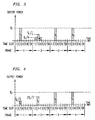
- an interference-compensating signal is transmitted at the compensation frequency in the initial frames, at increasing power levels in successive frames, prior to the commencement of transmission of the information-bearing bursts.
- an interference-compensating signal is transmitted at the power level of P 0 /3 at compensation frequency f c during time slot 3 of frame 1, and at power level 2P 0 /3 at frequency f c during time slot 3 of frame 2.
- the information-bearing burst is transmitted at full power, P 0 , at its assigned frequency f n during its assigned time slot 3. The gradual introduction of transmitted power thus reduces the low- frequency signal components produced.
- the duration of the interference-compensating burst is adjusted to match the duration of the corresponding information-bearing bursts.
- the protocol requires the simultaneous use of several bursts of different sizes and power levels in the same TDMA frame.
- the omitted bursts are replaced with interference-compensating bursts at the compensating frequency that match the energy contents of the corresponding missing information-bearing bursts.
- information-bearing bursts that are shorter than others are extended in length so that all bursts become equal in size.
- the extension can be accomplished by transmitting at the compensating frequency, f c , at substantially the same power level, P 0 , as that of the burst being extended, for a period of time equal in duration to the desired extension, immediately following (or preceding) the burst being extended.
- FIG. 5 illustrates this embodiment.
- the transmitter needs to quickly switch from the frequency f n of the information-bearing burst, to the frequency f c of the compensating signal during the extension period.
- the invention can be applied as previously discussed to achieve the advantageous reduction in baseband envelope interference.
- the advantage of this second more complicated technique rather than the first technique described above in a system with variable burst lengths is that, by effectively making the length of all bursts the same, the reduction of the unwanted low-frequency components of the baseband envelope interference can be made more complete. This is particularly important if the protocol requires frequent, rapid switching from bursts of one length to bursts of a different length.
- the embodiment of the invention in FIG. 6 can also be used if signal components at the fundamental frequency of the frame rate cause interference with certain devices, but which devices are not susceptible to signal components at multiples of the frame rate.
- a compensating signal is transmitted at frequency f c within a time slot in every frame.
- the compensating signal at the same power level, P 0 of the information-bearing signal, is transmitted in slot 7 of each frame.
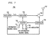
- an information-bearing signal to be transmitted is inputted on lead 701 through a selector 702, controlled by a controller 705, to a modulator 704, which modulates the signal for transmission with a carrier frequency outputted by a controllable oscillator 703.
- Oscillator 603 is controlled in frequency by the controller 705, which determines from a system controller (not shown) the frequency f n at which the transmitter 700 is to transmit its bursts of information.
- Controller 705 also controls the timing at which the unmodulated carrier output of oscillator 703 changes frequency to the frequency f c of the interference-compensating signal.
- Bursts of the modulated information-bearing signal are amplified an amplifier 706, controlled by the controller 705, and passed to an antenna 707.
- the interference-compensating signal, outputted by the oscillator 703 at the compensation frequency f c may be modulated by modulator 704 by a non-information-bearing signal inputted on lead 708 to selector 702.
- the oscillator output at compensation frequency f c may pass unmodulated by modulator 704, in response to a "no modulation" signal on input lead 709 to selector 702.
- the output of selector 702 of the information-bearing signal on lead 701, the non-information-bearing signal on lead 708, or the "no modulation" signal on lead 709 are determined by controller 705.
- Controller 705 has stored in an associated memory (not shown) timing and frame pattern information associated with terminal 700. Accordingly, it "knows" for each time slot of each frame whether the transmitter is in a mode to be 1) transmitting a burst of an information-bearing signal, 2) transmitting an interference-compensating signal, or 3) is in a quiet mode during which no transmission is to take place. Thus it controls oscillator 703 to output a carrier frequency appropriate to the each of the three modes and controls selector 702 to provide the appropriate modulating or non-modulating signal to modulator 704.
- Controller 705 further controls amplifier 706 to turn-off amplification to produce a zero output during the quiet mode and to amplify its input signal at other times with the amount of amplification being adjusted to achieve the desired transmitted power level.
- the interference-compensating signal is selected for output during those frames in which the usual steady-state power level of the information-bearing signal is not transmitted at all, is transmitted at a reduced power level, and/or is transmitted for less than its usual time slot duration.
- the frequency of oscillator 703 is adjusted to f c and the interference-compensating signal is transmitted in place of the information-bearing burst in either the same or a nearby time slot within the frame. If the protocol requires the information-bearing signal be transmitted at a reduced power level, then controller 705 adjusts the amplification of amplifier 706 during the time slot of the information-bearing burst, adjusts the frequency of oscillator 703 to f c , and selects the interference-compensating signal for transmission during the frame at another time slot and at an appropriate power level necessary to compensate for the reduced-power burst.
- controller 705 adjusts the frequency of oscillator 703 and transmits the interference-compensating signal as an extension of the burst during a duration necessary to compensate for the shortened burst.
Landscapes
- Engineering & Computer Science (AREA)
- Computer Networks & Wireless Communication (AREA)
- Signal Processing (AREA)
- Mobile Radio Communication Systems (AREA)
- Time-Division Multiplex Systems (AREA)
Claims (20)
- Procédé d'exploitation d'un émetteur à accès multiple à répartition dans le temps (700), comprenant les étapes de :CARACTERISE PARémission de rafales d'un signal porteur d'informations (701) dans des trames prédéterminées de trames (figure 2 - Trame 1) qui consistent chacune en un nombre prédéterminé de tranches de temps, la rafale dans chacune desdites trames prédéterminées étant émise à une fréquence porteuse prédéterminée (fn) dans une ou plusieurs premières tranches de temps numérotées prédéterminées desdites tranches de temps (figure 2 - Trame 1-Tranche de Temps 3) pendant une durée prédéterminée à un niveau de puissance prédéterminé,
dans des trames autres que lesdites trames prédéterminées desdites trames (figure 2 - Trame 2), lesdites autres trames étant celles dans lesquelles une rafale dudit signal porteur d'informations n'est pas émise (figure 2) ou est émise non audit niveau de puissance prédéterminé (figure 3) et/ou non pendant ladite durée prédéterminée (figure 5), l'émission d'un signal compensateur d'interférence (708) à une fréquence de compensation (fc) différente de ladite fréquence porteuse, ledit signal compensateur d'interférence étant émis durant une ou plusieurs desdites premières tranches de temps prédéterminées desdites autres trames, mais dans moins que toutes les tranches de temps desdites autres trames. - Procédé selon la revendication 1, dans lequel dans lesdites autres trames ledit signal compensateur d'interférence est émis dans la tranche de temps de même numéro que la tranche de temps dans laquelle des rafales dudit signal porteur d'informations sont émises dans lesdites trames prédéterminées.
- Procédé selon la revendication 1, dans lequel ledit signal compensateur d'interférence est émis dans au moins une tranche de temps numérotée qui est adjacente à la tranche de temps dans laquelle une rafale de niveau de puissance réduit est émise.
- Procédé selon la revendication 3, dans lequel la durée dudit signal compensateur d'interférence est égale à ladite durée prédéterminée de ladite rafale.
- Procédé selon la revendication 4, dans lequel le niveau de puissance dudit signal compensateur d'interférence est égal à la différence entre ledit niveau de puissance prédéterminé et le niveau de puissance réduit.
- Procédé selon la revendication 1, dans lequel dans chacune desdites autres trames dans laquelle la durée de la rafale est inférieure à la durée de ladite tranche de temps prédéterminée desdites tranches de temps, la durée dudit signal compensateur d'interférence dans chaque telle trame est approximativement égale à la différence entre la durée d'une dite tranche de temps prédéterminée desdites tranches de temps et la durée de la rafale dans ladite même trame.
- Procédé selon la revendication 6, dans lequel le niveau de puissance dudit signal compensateur d'interférence est égal audit niveau de puissance prédéterminé.
- Procédé d'exploitation d'un émetteur à accès multiple à répartition dans le temps (700), comprenant les étapes de :CARACTERISE PARémission de rafales d'un signal porteur d'informations (701) dans des trames (figure 2) qui consistent chacune en un nombre prédéterminé de tranches de temps, la rafale étant émise à une fréquence porteuse prédéterminée (fn) dans une ou plusieurs premières tranches de temps numérotées prédéterminées desdites tranches de temps (figure 2 - Trame 1-Tranche de Temps 3) pendant une durée prédéterminée à un niveau de puissance prédéterminé,
à la mise en marche de l'émetteur, dans au moins une trame antérieure (figure 4 - Trame 1) à une trame dans laquelle une rafale d'un signal porteur d'informations est émise la première fois à la mise en marche (figure 4 - Trame 3), l'émission d'un signal compensateur d'interférence (fc) à une fréquence de compensation différente de ladite fréquence porteuse dans une ou plusieurs deuxièmes tranches de temps numérotées prédéterminées desdites tanches de temps, d'au moins une trame antérieure, à un niveau de puissance inférieur audit niveau de puissance prédéterminé. - Procédé selon la revendication 8, dans lequel ladite deuxième tranche de temps prédéterminée numérotée desdites tranches de temps est la tranche de temps de même numéro que ladite première tranche de temps numérotée prédéterminée.
- Procédé selon la revendication 9, dans lequel un signal compensateur d'interférence est émis dans une pluralité de tranches de temps successives antérieures à une trame dans laquelle une rafale d'un signal porteur d'informations est émise la première fois, le niveau de puissance du signal compensateur d'interférence dans chacune de telles trames étant accru d'une trame successive à la suivante.
- Emetteur à accès multiple à répartition dans le temps (700), comprenant :CARACTERISE PARun moyen pour émettre des rafales d'un signal porteur d'informations (701) dans des trames prédéterminées de trames (figure 2 - Trame 1) qui consistent chacune en un nombre prédéterminé de tranches de temps, la rafale dans chacune desdites trames prédéterminées de trames étant émise à une fréquence porteuse prédéterminée (fn) dans une ou plusieurs premières tranches de temps numérotées prédéterminées desdites tranches de temps (figure 2 - Trame 1-Tranche de Temps 3) pendant une durée prédéterminée à un niveau de puissance prédéterminé, et
un moyen pour émettre un signal compensateur d'interférence (fc) à une fréquence de compensation différente de ladite fréquence porteuse dans des trames autres que lesdites trames prédéterminées desdites trames (figure 2 - Trame 2), lesdites autres trames étant celles dans lesquelles une rafale dudit signal porteur d'informations n'est pas émise (figure 2) ou est émise non audit niveau de puissance prédéterminé (figure 3) et/ou non pendant ladite durée prédéterminée (figure 5), ledit signal compensateur d'interférence étant émis durant une ou plusieurs desdites premières tranches de temps prédéterminées desdites autres trames, mais dans moins que toutes les tranches de temps desdites autres trames. - Emetteur selon la revendication 11, dans lequel dans lesdites autres trames ledit signal compensateur d'interférence est émis dans la tranche de temps de même numéro que la tranche de temps dans laquelle des rafales dudit signal porteur d'informations sont émises dans lesdites trames prédéterminées de trames.
- Emetteur selon la revendication 11, dans lequel ledit signal compensateur d'interférence est émis dans au moins une tranche de temps numérotée qui est adjacente à la tranche de temps dans laquelle une rafale de niveau de puissance réduit est émise.
- Emetteur selon la revendication 13, dans lequel la durée dudit signal compensateur d'interférence est égale à ladite durée prédéterminée de chacune desdites rafales.
- Emetteur selon la revendication 14, dans lequel le niveau de puissance dudit signal compensateur d'interférence est approximativement égal à la différence entre ledit niveau de puissance prédéterminé et le niveau de puissance réduit.
- Emetteur selon la revendication 11, dans lequel dans chacune desdites autres trames dans laquelle la durée de la rafale est inférieure à la durée de ladite tranche de temps prédéterminée desdites tranches de temps, la durée dudit signal compensateur d'interférence dans chaque telle trame est approximativement égale à la différence entre la durée d'une tranche de temps prédéterminée desdites tranches de temps et la durée de la rafale dans ladite même trame.
- Emetteur selon la revendication 16, dans lequel le niveau de puissance dudit signal compensateur d'interférence est égal audit niveau de puissance prédéterminé.
- Emetteur à accès multiple par répartition à répartition dans le temps (700), comprenant :CARACTERISE PARun moyen pour émettre des rafales d'un signal porteur d'informations (701) dans des trames (figure 2 - Trame 1) qui consistent chacune en un nombre prédéterminé de tranches de temps, chaque rafale étant émise à une fréquence porteuse prédéterminée (fn) dans une ou plusieurs premières tranches de temps numérotées prédéterminées desdites tranches de temps (figure 2 - Trame 1-Tranche de Temps 3) pendant une durée prédéterminée à un niveau de puissance prédéterminé, et
un moyen pour émettre (708) un signal compensateur d'interférence à une fréquence de compensation (fc) différente de ladite fréquence porteuse dans une ou plusieurs deuxièmes tranches de temps numérotées prédéterminées desdites tranches de temps à un niveau de puissance inférieur audit niveau de puissance prédéterminé à la mise en marche de l'émetteur, ledit signal compensateur d'interférence étant émis dans au moins une trame antérieure (figure 4 - Trame 1) à une trame dans laquelle une rafale d'un signal porteur d'informations est émise la première fois à la mise en marche (figure 4 - Trame 3), - Emetteur selon la revendication 18, dans lequel ladite deuxième tranche de temps numérotée prédéterminée desdites tranches de temps est la tranche de temps de même numéro que ladite première tranche de temps numérotée prédéterminée.
- Emetteur selon la revendication 19, dans lequel ledit moyen d'émission d'un signal compensateur d'interférence émet dans une pluralité de tranches de temps successives antérieures à une trame dans laquelle une rafale d'un signal porteur d'informations est émise la première fois, le niveau de puissance du signal compensateur d'interférence dans chacune de telles trames étant accru d'une trame successive à la suivante.
Priority Applications (2)
| Application Number | Priority Date | Filing Date | Title |
|---|---|---|---|
| EP19970303255 EP0878928B1 (fr) | 1997-05-13 | 1997-05-13 | Transmetteur AMRT avec moyens pour la réduction d'interférences |
| DE1997614706 DE69714706T2 (de) | 1997-05-13 | 1997-05-13 | TDMA Funksender mit Interferenzbegrenzung |
Applications Claiming Priority (1)
| Application Number | Priority Date | Filing Date | Title |
|---|---|---|---|
| EP19970303255 EP0878928B1 (fr) | 1997-05-13 | 1997-05-13 | Transmetteur AMRT avec moyens pour la réduction d'interférences |
Publications (2)
| Publication Number | Publication Date |
|---|---|
| EP0878928A1 EP0878928A1 (fr) | 1998-11-18 |
| EP0878928B1 true EP0878928B1 (fr) | 2002-08-14 |
Family
ID=8229329
Family Applications (1)
| Application Number | Title | Priority Date | Filing Date |
|---|---|---|---|
| EP19970303255 Expired - Lifetime EP0878928B1 (fr) | 1997-05-13 | 1997-05-13 | Transmetteur AMRT avec moyens pour la réduction d'interférences |
Country Status (2)
| Country | Link |
|---|---|
| EP (1) | EP0878928B1 (fr) |
| DE (1) | DE69714706T2 (fr) |
Cited By (3)
| Publication number | Priority date | Publication date | Assignee | Title |
|---|---|---|---|---|
| US7929723B2 (en) | 1997-01-13 | 2011-04-19 | Micro Ear Technology, Inc. | Portable system for programming hearing aids |
| US8300862B2 (en) | 2006-09-18 | 2012-10-30 | Starkey Kaboratories, Inc | Wireless interface for programming hearing assistance devices |
| US9344817B2 (en) | 2000-01-20 | 2016-05-17 | Starkey Laboratories, Inc. | Hearing aid systems |
Families Citing this family (2)
| Publication number | Priority date | Publication date | Assignee | Title |
|---|---|---|---|---|
| WO2001037439A2 (fr) * | 1999-11-03 | 2001-05-25 | Telefonaktiebolaget L M Ericsson (Publ) | Systeme et procede de suppression du bruit dans un signal de communication |
| US7130288B2 (en) | 2001-01-24 | 2006-10-31 | Qualcomm Incorporated | Method for power control for mixed voice and data transmission |
Family Cites Families (2)
| Publication number | Priority date | Publication date | Assignee | Title |
|---|---|---|---|---|
| GB2238449B (en) * | 1989-11-10 | 1993-11-24 | Trade And Industry Secretary O | Improvements in or relating to TDMA systems |
| US5812936A (en) * | 1995-09-19 | 1998-09-22 | Lucent Technologies, Inc. | Energy-efficient time-division radio that reduces the induction of baseband interference |
-
1997
- 1997-05-13 DE DE1997614706 patent/DE69714706T2/de not_active Expired - Fee Related
- 1997-05-13 EP EP19970303255 patent/EP0878928B1/fr not_active Expired - Lifetime
Cited By (4)
| Publication number | Priority date | Publication date | Assignee | Title |
|---|---|---|---|---|
| US7929723B2 (en) | 1997-01-13 | 2011-04-19 | Micro Ear Technology, Inc. | Portable system for programming hearing aids |
| US9344817B2 (en) | 2000-01-20 | 2016-05-17 | Starkey Laboratories, Inc. | Hearing aid systems |
| US9357317B2 (en) | 2000-01-20 | 2016-05-31 | Starkey Laboratories, Inc. | Hearing aid systems |
| US8300862B2 (en) | 2006-09-18 | 2012-10-30 | Starkey Kaboratories, Inc | Wireless interface for programming hearing assistance devices |
Also Published As
| Publication number | Publication date |
|---|---|
| DE69714706T2 (de) | 2003-04-10 |
| DE69714706D1 (de) | 2002-09-19 |
| EP0878928A1 (fr) | 1998-11-18 |
Similar Documents
| Publication | Publication Date | Title |
|---|---|---|
| US5740165A (en) | Wireless TDMA transmitter with reduced interference | |
| KR100390125B1 (ko) | 시분할라디오의작동방법 | |
| JP4024859B2 (ja) | デジタル通信装置によって生成された干渉を減少させるシステムおよび方法 | |
| US5745842A (en) | Method and apparatus for controlling operation of a portable or mobile battery-operated radios | |
| JP3192839B2 (ja) | 初期送信電力の決定方法 | |
| US5809017A (en) | Method of minimizing undersirable RF emissions within a TDMA system | |
| US5933418A (en) | Method for increasing control channel capacity in a communication system | |
| US6693885B1 (en) | Method, mobile station and base station for transmitting signals | |
| EP1104119B1 (fr) | Emetteur avec reglage de la puissance de sortie | |
| EP0878928B1 (fr) | Transmetteur AMRT avec moyens pour la réduction d'interférences | |
| AU773521B2 (en) | Method for cell extension in a TDMA cellular telephone system | |
| KR20020014839A (ko) | 기지국 송신 장치와 그것을 이용한 cdma 이동 통신시스템 | |
| GB2331203A (en) | Defining transmission power according to previous transmission powers | |
| GB2238449A (en) | TDMA systems | |
| EP0765042A2 (fr) | Radioémetteur/-récepteur à multiplexage temporel avec une interférence de bande de base reduite | |
| JP3321025B2 (ja) | 時分割多元アクセス送信器 | |
| JPH08191224A (ja) | 移動通信装置 | |
| CN1201298A (zh) | 干扰被减低的无线时分多址发射机 | |
| HK1017527A (en) | Wireless tdma transmitter with reduced interference | |
| KR100456118B1 (ko) | 이동통신단말기의고출력증폭기출력조절장치 | |
| KR100231156B1 (ko) | 시디엠에이 방식 이동통신 단말기의 수신능력 개선장치 | |
| JPH0591010A (ja) | 通信方式 | |
| JPH1168655A (ja) | 移動機 | |
| KR20000027036A (ko) | 휴대용 무선 단말기와 무선 이어폰/마이크로폰사이의 통화채널 할당 장치 및 방법 | |
| JPH06244652A (ja) | 無線機用ブースタ |
Legal Events
| Date | Code | Title | Description |
|---|---|---|---|
| PUAI | Public reference made under article 153(3) epc to a published international application that has entered the european phase |
Free format text: ORIGINAL CODE: 0009012 |
|
| AK | Designated contracting states |
Kind code of ref document: A1 Designated state(s): DE ES FI FR GB SE |
|
| 17P | Request for examination filed |
Effective date: 19990510 |
|
| AKX | Designation fees paid |
Free format text: DE ES FI FR GB SE |
|
| 17Q | First examination report despatched |
Effective date: 20010404 |
|
| GRAG | Despatch of communication of intention to grant |
Free format text: ORIGINAL CODE: EPIDOS AGRA |
|
| GRAG | Despatch of communication of intention to grant |
Free format text: ORIGINAL CODE: EPIDOS AGRA |
|
| GRAH | Despatch of communication of intention to grant a patent |
Free format text: ORIGINAL CODE: EPIDOS IGRA |
|
| GRAH | Despatch of communication of intention to grant a patent |
Free format text: ORIGINAL CODE: EPIDOS IGRA |
|
| GRAA | (expected) grant |
Free format text: ORIGINAL CODE: 0009210 |
|
| AK | Designated contracting states |
Kind code of ref document: B1 Designated state(s): DE ES FI FR GB SE |
|
| PG25 | Lapsed in a contracting state [announced via postgrant information from national office to epo] |
Ref country code: FI Free format text: LAPSE BECAUSE OF FAILURE TO SUBMIT A TRANSLATION OF THE DESCRIPTION OR TO PAY THE FEE WITHIN THE PRESCRIBED TIME-LIMIT Effective date: 20020814 |
|
| REG | Reference to a national code |
Ref country code: GB Ref legal event code: FG4D |
|
| REF | Corresponds to: |
Ref document number: 69714706 Country of ref document: DE Date of ref document: 20020919 |
|
| PG25 | Lapsed in a contracting state [announced via postgrant information from national office to epo] |
Ref country code: SE Free format text: LAPSE BECAUSE OF FAILURE TO SUBMIT A TRANSLATION OF THE DESCRIPTION OR TO PAY THE FEE WITHIN THE PRESCRIBED TIME-LIMIT Effective date: 20021114 |
|
| ET | Fr: translation filed | ||
| PG25 | Lapsed in a contracting state [announced via postgrant information from national office to epo] |
Ref country code: ES Free format text: LAPSE BECAUSE OF FAILURE TO SUBMIT A TRANSLATION OF THE DESCRIPTION OR TO PAY THE FEE WITHIN THE PRESCRIBED TIME-LIMIT Effective date: 20030228 |
|
| PLBE | No opposition filed within time limit |
Free format text: ORIGINAL CODE: 0009261 |
|
| STAA | Information on the status of an ep patent application or granted ep patent |
Free format text: STATUS: NO OPPOSITION FILED WITHIN TIME LIMIT |
|
| 26N | No opposition filed |
Effective date: 20030515 |
|
| PGFP | Annual fee paid to national office [announced via postgrant information from national office to epo] |
Ref country code: DE Payment date: 20070522 Year of fee payment: 11 |
|
| PGFP | Annual fee paid to national office [announced via postgrant information from national office to epo] |
Ref country code: GB Payment date: 20070522 Year of fee payment: 11 |
|
| PGFP | Annual fee paid to national office [announced via postgrant information from national office to epo] |
Ref country code: FR Payment date: 20070516 Year of fee payment: 11 |
|
| GBPC | Gb: european patent ceased through non-payment of renewal fee |
Effective date: 20080513 |
|
| REG | Reference to a national code |
Ref country code: FR Ref legal event code: ST Effective date: 20090119 |
|
| PG25 | Lapsed in a contracting state [announced via postgrant information from national office to epo] |
Ref country code: FR Free format text: LAPSE BECAUSE OF NON-PAYMENT OF DUE FEES Effective date: 20080602 Ref country code: DE Free format text: LAPSE BECAUSE OF NON-PAYMENT OF DUE FEES Effective date: 20081202 |
|
| PG25 | Lapsed in a contracting state [announced via postgrant information from national office to epo] |
Ref country code: GB Free format text: LAPSE BECAUSE OF NON-PAYMENT OF DUE FEES Effective date: 20080513 |