EP0879131B1 - Appareil et procede d'extrusion, produit tubulaire et tuyau - Google Patents
Appareil et procede d'extrusion, produit tubulaire et tuyau Download PDFInfo
- Publication number
- EP0879131B1 EP0879131B1 EP96918716A EP96918716A EP0879131B1 EP 0879131 B1 EP0879131 B1 EP 0879131B1 EP 96918716 A EP96918716 A EP 96918716A EP 96918716 A EP96918716 A EP 96918716A EP 0879131 B1 EP0879131 B1 EP 0879131B1
- Authority
- EP
- European Patent Office
- Prior art keywords
- extrusion apparatus
- rotor
- plastic
- stator
- extruded
- Prior art date
- Legal status (The legal status is an assumption and is not a legal conclusion. Google has not performed a legal analysis and makes no representation as to the accuracy of the status listed.)
- Expired - Lifetime
Links
Images


Classifications
-
- B—PERFORMING OPERATIONS; TRANSPORTING
- B32—LAYERED PRODUCTS
- B32B—LAYERED PRODUCTS, i.e. PRODUCTS BUILT-UP OF STRATA OF FLAT OR NON-FLAT, e.g. CELLULAR OR HONEYCOMB, FORM
- B32B1/00—Layered products having a non-planar shape
- B32B1/08—Tubular products
-
- B—PERFORMING OPERATIONS; TRANSPORTING
- B29—WORKING OF PLASTICS; WORKING OF SUBSTANCES IN A PLASTIC STATE IN GENERAL
- B29C—SHAPING OR JOINING OF PLASTICS; SHAPING OF MATERIAL IN A PLASTIC STATE, NOT OTHERWISE PROVIDED FOR; AFTER-TREATMENT OF THE SHAPED PRODUCTS, e.g. REPAIRING
- B29C44/00—Shaping by internal pressure generated in the material, e.g. swelling or foaming ; Producing porous or cellular expanded plastics articles
- B29C44/20—Shaping by internal pressure generated in the material, e.g. swelling or foaming ; Producing porous or cellular expanded plastics articles for articles of indefinite length
- B29C44/22—Shaping by internal pressure generated in the material, e.g. swelling or foaming ; Producing porous or cellular expanded plastics articles for articles of indefinite length consisting of at least two parts of chemically or physically different materials, e.g. having different densities
-
- B—PERFORMING OPERATIONS; TRANSPORTING
- B29—WORKING OF PLASTICS; WORKING OF SUBSTANCES IN A PLASTIC STATE IN GENERAL
- B29C—SHAPING OR JOINING OF PLASTICS; SHAPING OF MATERIAL IN A PLASTIC STATE, NOT OTHERWISE PROVIDED FOR; AFTER-TREATMENT OF THE SHAPED PRODUCTS, e.g. REPAIRING
- B29C48/00—Extrusion moulding, i.e. expressing the moulding material through a die or nozzle which imparts the desired form; Apparatus therefor
- B29C48/03—Extrusion moulding, i.e. expressing the moulding material through a die or nozzle which imparts the desired form; Apparatus therefor characterised by the shape of the extruded material at extrusion
- B29C48/09—Articles with cross-sections having partially or fully enclosed cavities, e.g. pipes or channels
-
- B—PERFORMING OPERATIONS; TRANSPORTING
- B29—WORKING OF PLASTICS; WORKING OF SUBSTANCES IN A PLASTIC STATE IN GENERAL
- B29C—SHAPING OR JOINING OF PLASTICS; SHAPING OF MATERIAL IN A PLASTIC STATE, NOT OTHERWISE PROVIDED FOR; AFTER-TREATMENT OF THE SHAPED PRODUCTS, e.g. REPAIRING
- B29C48/00—Extrusion moulding, i.e. expressing the moulding material through a die or nozzle which imparts the desired form; Apparatus therefor
- B29C48/15—Extrusion moulding, i.e. expressing the moulding material through a die or nozzle which imparts the desired form; Apparatus therefor incorporating preformed parts or layers, e.g. extrusion moulding around inserts
- B29C48/151—Coating hollow articles
- B29C48/152—Coating hollow articles the inner surfaces thereof
-
- B—PERFORMING OPERATIONS; TRANSPORTING
- B29—WORKING OF PLASTICS; WORKING OF SUBSTANCES IN A PLASTIC STATE IN GENERAL
- B29C—SHAPING OR JOINING OF PLASTICS; SHAPING OF MATERIAL IN A PLASTIC STATE, NOT OTHERWISE PROVIDED FOR; AFTER-TREATMENT OF THE SHAPED PRODUCTS, e.g. REPAIRING
- B29C48/00—Extrusion moulding, i.e. expressing the moulding material through a die or nozzle which imparts the desired form; Apparatus therefor
- B29C48/16—Articles comprising two or more components, e.g. co-extruded layers
- B29C48/18—Articles comprising two or more components, e.g. co-extruded layers the components being layers
- B29C48/21—Articles comprising two or more components, e.g. co-extruded layers the components being layers the layers being joined at their surfaces
-
- B—PERFORMING OPERATIONS; TRANSPORTING
- B29—WORKING OF PLASTICS; WORKING OF SUBSTANCES IN A PLASTIC STATE IN GENERAL
- B29C—SHAPING OR JOINING OF PLASTICS; SHAPING OF MATERIAL IN A PLASTIC STATE, NOT OTHERWISE PROVIDED FOR; AFTER-TREATMENT OF THE SHAPED PRODUCTS, e.g. REPAIRING
- B29C48/00—Extrusion moulding, i.e. expressing the moulding material through a die or nozzle which imparts the desired form; Apparatus therefor
- B29C48/25—Component parts, details or accessories; Auxiliary operations
- B29C48/30—Extrusion nozzles or dies
- B29C48/32—Extrusion nozzles or dies with annular openings, e.g. for forming tubular articles
- B29C48/33—Extrusion nozzles or dies with annular openings, e.g. for forming tubular articles with parts rotatable relative to each other
-
- B—PERFORMING OPERATIONS; TRANSPORTING
- B29—WORKING OF PLASTICS; WORKING OF SUBSTANCES IN A PLASTIC STATE IN GENERAL
- B29C—SHAPING OR JOINING OF PLASTICS; SHAPING OF MATERIAL IN A PLASTIC STATE, NOT OTHERWISE PROVIDED FOR; AFTER-TREATMENT OF THE SHAPED PRODUCTS, e.g. REPAIRING
- B29C48/00—Extrusion moulding, i.e. expressing the moulding material through a die or nozzle which imparts the desired form; Apparatus therefor
- B29C48/25—Component parts, details or accessories; Auxiliary operations
- B29C48/30—Extrusion nozzles or dies
- B29C48/32—Extrusion nozzles or dies with annular openings, e.g. for forming tubular articles
- B29C48/335—Multiple annular extrusion nozzles in coaxial arrangement, e.g. for making multi-layered tubular articles
- B29C48/336—Multiple annular extrusion nozzles in coaxial arrangement, e.g. for making multi-layered tubular articles the components merging one by one down streams in the die
- B29C48/3366—Multiple annular extrusion nozzles in coaxial arrangement, e.g. for making multi-layered tubular articles the components merging one by one down streams in the die using a die with concentric parts, e.g. rings, cylinders
-
- B—PERFORMING OPERATIONS; TRANSPORTING
- B29—WORKING OF PLASTICS; WORKING OF SUBSTANCES IN A PLASTIC STATE IN GENERAL
- B29C—SHAPING OR JOINING OF PLASTICS; SHAPING OF MATERIAL IN A PLASTIC STATE, NOT OTHERWISE PROVIDED FOR; AFTER-TREATMENT OF THE SHAPED PRODUCTS, e.g. REPAIRING
- B29C48/00—Extrusion moulding, i.e. expressing the moulding material through a die or nozzle which imparts the desired form; Apparatus therefor
- B29C48/25—Component parts, details or accessories; Auxiliary operations
- B29C48/36—Means for plasticising or homogenising the moulding material or forcing it through the nozzle or die
- B29C48/465—Means for plasticising or homogenising the moulding material or forcing it through the nozzle or die using rollers
- B29C48/467—Means for plasticising or homogenising the moulding material or forcing it through the nozzle or die using rollers using single rollers, e.g. provided with protrusions, closely surrounded by a housing with movement of the material in the axial direction
- B29C48/468—Cavity transfer mixing devices, i.e. a roller and surrounding barrel both provided with cavities; Barrels and rollers therefor
-
- B—PERFORMING OPERATIONS; TRANSPORTING
- B29—WORKING OF PLASTICS; WORKING OF SUBSTANCES IN A PLASTIC STATE IN GENERAL
- B29C—SHAPING OR JOINING OF PLASTICS; SHAPING OF MATERIAL IN A PLASTIC STATE, NOT OTHERWISE PROVIDED FOR; AFTER-TREATMENT OF THE SHAPED PRODUCTS, e.g. REPAIRING
- B29C48/00—Extrusion moulding, i.e. expressing the moulding material through a die or nozzle which imparts the desired form; Apparatus therefor
- B29C48/25—Component parts, details or accessories; Auxiliary operations
- B29C48/36—Means for plasticising or homogenising the moulding material or forcing it through the nozzle or die
- B29C48/50—Details of extruders
- B29C48/695—Flow dividers, e.g. breaker plates
- B29C48/70—Flow dividers, e.g. breaker plates comprising means for dividing, distributing and recombining melt flows
- B29C48/705—Flow dividers, e.g. breaker plates comprising means for dividing, distributing and recombining melt flows in the die zone, e.g. to create flow homogeneity
-
- B—PERFORMING OPERATIONS; TRANSPORTING
- B29—WORKING OF PLASTICS; WORKING OF SUBSTANCES IN A PLASTIC STATE IN GENERAL
- B29C—SHAPING OR JOINING OF PLASTICS; SHAPING OF MATERIAL IN A PLASTIC STATE, NOT OTHERWISE PROVIDED FOR; AFTER-TREATMENT OF THE SHAPED PRODUCTS, e.g. REPAIRING
- B29C48/00—Extrusion moulding, i.e. expressing the moulding material through a die or nozzle which imparts the desired form; Apparatus therefor
- B29C48/25—Component parts, details or accessories; Auxiliary operations
- B29C48/36—Means for plasticising or homogenising the moulding material or forcing it through the nozzle or die
- B29C48/50—Details of extruders
- B29C48/76—Venting, drying means; Degassing means
-
- B—PERFORMING OPERATIONS; TRANSPORTING
- B29—WORKING OF PLASTICS; WORKING OF SUBSTANCES IN A PLASTIC STATE IN GENERAL
- B29C—SHAPING OR JOINING OF PLASTICS; SHAPING OF MATERIAL IN A PLASTIC STATE, NOT OTHERWISE PROVIDED FOR; AFTER-TREATMENT OF THE SHAPED PRODUCTS, e.g. REPAIRING
- B29C48/00—Extrusion moulding, i.e. expressing the moulding material through a die or nozzle which imparts the desired form; Apparatus therefor
- B29C48/25—Component parts, details or accessories; Auxiliary operations
- B29C48/88—Thermal treatment of the stream of extruded material, e.g. cooling
- B29C48/90—Thermal treatment of the stream of extruded material, e.g. cooling with calibration or sizing, i.e. combined with fixing or setting of the final dimensions of the extruded article
- B29C48/901—Thermal treatment of the stream of extruded material, e.g. cooling with calibration or sizing, i.e. combined with fixing or setting of the final dimensions of the extruded article of hollow bodies
- B29C48/903—Thermal treatment of the stream of extruded material, e.g. cooling with calibration or sizing, i.e. combined with fixing or setting of the final dimensions of the extruded article of hollow bodies externally
-
- B—PERFORMING OPERATIONS; TRANSPORTING
- B29—WORKING OF PLASTICS; WORKING OF SUBSTANCES IN A PLASTIC STATE IN GENERAL
- B29C—SHAPING OR JOINING OF PLASTICS; SHAPING OF MATERIAL IN A PLASTIC STATE, NOT OTHERWISE PROVIDED FOR; AFTER-TREATMENT OF THE SHAPED PRODUCTS, e.g. REPAIRING
- B29C55/00—Shaping by stretching, e.g. drawing through a die; Apparatus therefor
- B29C55/22—Shaping by stretching, e.g. drawing through a die; Apparatus therefor of tubes
- B29C55/24—Shaping by stretching, e.g. drawing through a die; Apparatus therefor of tubes radial
-
- B—PERFORMING OPERATIONS; TRANSPORTING
- B29—WORKING OF PLASTICS; WORKING OF SUBSTANCES IN A PLASTIC STATE IN GENERAL
- B29C—SHAPING OR JOINING OF PLASTICS; SHAPING OF MATERIAL IN A PLASTIC STATE, NOT OTHERWISE PROVIDED FOR; AFTER-TREATMENT OF THE SHAPED PRODUCTS, e.g. REPAIRING
- B29C63/00—Lining or sheathing, i.e. applying preformed layers or sheathings of plastics; Apparatus therefor
- B29C63/26—Lining or sheathing of internal surfaces
- B29C63/34—Lining or sheathing of internal surfaces using tubular layers or sheathings
-
- B—PERFORMING OPERATIONS; TRANSPORTING
- B29—WORKING OF PLASTICS; WORKING OF SUBSTANCES IN A PLASTIC STATE IN GENERAL
- B29C—SHAPING OR JOINING OF PLASTICS; SHAPING OF MATERIAL IN A PLASTIC STATE, NOT OTHERWISE PROVIDED FOR; AFTER-TREATMENT OF THE SHAPED PRODUCTS, e.g. REPAIRING
- B29C70/00—Shaping composites, i.e. plastics material comprising reinforcements, fillers or preformed parts, e.g. inserts
- B29C70/04—Shaping composites, i.e. plastics material comprising reinforcements, fillers or preformed parts, e.g. inserts comprising reinforcements only, e.g. self-reinforcing plastics
- B29C70/28—Shaping operations therefor
- B29C70/40—Shaping or impregnating by compression not applied
- B29C70/50—Shaping or impregnating by compression not applied for producing articles of indefinite length, e.g. prepregs, sheet moulding compounds [SMC] or cross moulding compounds [XMC]
-
- B—PERFORMING OPERATIONS; TRANSPORTING
- B32—LAYERED PRODUCTS
- B32B—LAYERED PRODUCTS, i.e. PRODUCTS BUILT-UP OF STRATA OF FLAT OR NON-FLAT, e.g. CELLULAR OR HONEYCOMB, FORM
- B32B15/00—Layered products comprising a layer of metal
- B32B15/04—Layered products comprising a layer of metal comprising metal as the main or only constituent of a layer, which is next to another layer of the same or of a different material
- B32B15/08—Layered products comprising a layer of metal comprising metal as the main or only constituent of a layer, which is next to another layer of the same or of a different material of synthetic resin
-
- B—PERFORMING OPERATIONS; TRANSPORTING
- B32—LAYERED PRODUCTS
- B32B—LAYERED PRODUCTS, i.e. PRODUCTS BUILT-UP OF STRATA OF FLAT OR NON-FLAT, e.g. CELLULAR OR HONEYCOMB, FORM
- B32B7/00—Layered products characterised by the relation between layers; Layered products characterised by the relative orientation of features between layers, or by the relative values of a measurable parameter between layers, i.e. products comprising layers having different physical, chemical or physicochemical properties; Layered products characterised by the interconnection of layers
- B32B7/04—Interconnection of layers
- B32B7/12—Interconnection of layers using interposed adhesives or interposed materials with bonding properties
-
- F—MECHANICAL ENGINEERING; LIGHTING; HEATING; WEAPONS; BLASTING
- F16—ENGINEERING ELEMENTS AND UNITS; GENERAL MEASURES FOR PRODUCING AND MAINTAINING EFFECTIVE FUNCTIONING OF MACHINES OR INSTALLATIONS; THERMAL INSULATION IN GENERAL
- F16L—PIPES; JOINTS OR FITTINGS FOR PIPES; SUPPORTS FOR PIPES, CABLES OR PROTECTIVE TUBING; MEANS FOR THERMAL INSULATION IN GENERAL
- F16L11/00—Hoses, i.e. flexible pipes
- F16L11/14—Hoses, i.e. flexible pipes made of rigid material, e.g. metal or hard plastics
- F16L11/15—Hoses, i.e. flexible pipes made of rigid material, e.g. metal or hard plastics corrugated
-
- F—MECHANICAL ENGINEERING; LIGHTING; HEATING; WEAPONS; BLASTING
- F16—ENGINEERING ELEMENTS AND UNITS; GENERAL MEASURES FOR PRODUCING AND MAINTAINING EFFECTIVE FUNCTIONING OF MACHINES OR INSTALLATIONS; THERMAL INSULATION IN GENERAL
- F16L—PIPES; JOINTS OR FITTINGS FOR PIPES; SUPPORTS FOR PIPES, CABLES OR PROTECTIVE TUBING; MEANS FOR THERMAL INSULATION IN GENERAL
- F16L55/00—Devices or appurtenances for use in, or in connection with, pipes or pipe systems
- F16L55/16—Devices for covering leaks in pipes or hoses, e.g. hose-menders
- F16L55/162—Devices for covering leaks in pipes or hoses, e.g. hose-menders from inside the pipe
-
- F—MECHANICAL ENGINEERING; LIGHTING; HEATING; WEAPONS; BLASTING
- F16—ENGINEERING ELEMENTS AND UNITS; GENERAL MEASURES FOR PRODUCING AND MAINTAINING EFFECTIVE FUNCTIONING OF MACHINES OR INSTALLATIONS; THERMAL INSULATION IN GENERAL
- F16L—PIPES; JOINTS OR FITTINGS FOR PIPES; SUPPORTS FOR PIPES, CABLES OR PROTECTIVE TUBING; MEANS FOR THERMAL INSULATION IN GENERAL
- F16L9/00—Rigid pipes
- F16L9/12—Rigid pipes of plastics with or without reinforcement
- F16L9/121—Rigid pipes of plastics with or without reinforcement with three layers
-
- F—MECHANICAL ENGINEERING; LIGHTING; HEATING; WEAPONS; BLASTING
- F16—ENGINEERING ELEMENTS AND UNITS; GENERAL MEASURES FOR PRODUCING AND MAINTAINING EFFECTIVE FUNCTIONING OF MACHINES OR INSTALLATIONS; THERMAL INSULATION IN GENERAL
- F16L—PIPES; JOINTS OR FITTINGS FOR PIPES; SUPPORTS FOR PIPES, CABLES OR PROTECTIVE TUBING; MEANS FOR THERMAL INSULATION IN GENERAL
- F16L9/00—Rigid pipes
- F16L9/14—Compound tubes, i.e. made of materials not wholly covered by any one of the preceding groups
- F16L9/147—Compound tubes, i.e. made of materials not wholly covered by any one of the preceding groups comprising only layers of metal and plastics with or without reinforcement
-
- F—MECHANICAL ENGINEERING; LIGHTING; HEATING; WEAPONS; BLASTING
- F16—ENGINEERING ELEMENTS AND UNITS; GENERAL MEASURES FOR PRODUCING AND MAINTAINING EFFECTIVE FUNCTIONING OF MACHINES OR INSTALLATIONS; THERMAL INSULATION IN GENERAL
- F16L—PIPES; JOINTS OR FITTINGS FOR PIPES; SUPPORTS FOR PIPES, CABLES OR PROTECTIVE TUBING; MEANS FOR THERMAL INSULATION IN GENERAL
- F16L9/00—Rigid pipes
- F16L9/21—Rigid pipes made of sound-absorbing materials or with sound-absorbing structure
-
- G—PHYSICS
- G01—MEASURING; TESTING
- G01M—TESTING STATIC OR DYNAMIC BALANCE OF MACHINES OR STRUCTURES; TESTING OF STRUCTURES OR APPARATUS, NOT OTHERWISE PROVIDED FOR
- G01M3/00—Investigating fluid-tightness of structures
- G01M3/02—Investigating fluid-tightness of structures by using fluid or vacuum
- G01M3/04—Investigating fluid-tightness of structures by using fluid or vacuum by detecting the presence of fluid at the leakage point
- G01M3/16—Investigating fluid-tightness of structures by using fluid or vacuum by detecting the presence of fluid at the leakage point using electric detection means
- G01M3/18—Investigating fluid-tightness of structures by using fluid or vacuum by detecting the presence of fluid at the leakage point using electric detection means for pipes, cables or tubes; for pipe joints or seals; for valves; for welds; for containers, e.g. radiators
-
- B—PERFORMING OPERATIONS; TRANSPORTING
- B29—WORKING OF PLASTICS; WORKING OF SUBSTANCES IN A PLASTIC STATE IN GENERAL
- B29C—SHAPING OR JOINING OF PLASTICS; SHAPING OF MATERIAL IN A PLASTIC STATE, NOT OTHERWISE PROVIDED FOR; AFTER-TREATMENT OF THE SHAPED PRODUCTS, e.g. REPAIRING
- B29C48/00—Extrusion moulding, i.e. expressing the moulding material through a die or nozzle which imparts the desired form; Apparatus therefor
- B29C48/001—Combinations of extrusion moulding with other shaping operations
- B29C48/0018—Combinations of extrusion moulding with other shaping operations combined with shaping by orienting, stretching or shrinking, e.g. film blowing
-
- B—PERFORMING OPERATIONS; TRANSPORTING
- B29—WORKING OF PLASTICS; WORKING OF SUBSTANCES IN A PLASTIC STATE IN GENERAL
- B29C—SHAPING OR JOINING OF PLASTICS; SHAPING OF MATERIAL IN A PLASTIC STATE, NOT OTHERWISE PROVIDED FOR; AFTER-TREATMENT OF THE SHAPED PRODUCTS, e.g. REPAIRING
- B29C48/00—Extrusion moulding, i.e. expressing the moulding material through a die or nozzle which imparts the desired form; Apparatus therefor
- B29C48/03—Extrusion moulding, i.e. expressing the moulding material through a die or nozzle which imparts the desired form; Apparatus therefor characterised by the shape of the extruded material at extrusion
- B29C48/13—Articles with a cross-section varying in the longitudinal direction, e.g. corrugated pipes
-
- B—PERFORMING OPERATIONS; TRANSPORTING
- B29—WORKING OF PLASTICS; WORKING OF SUBSTANCES IN A PLASTIC STATE IN GENERAL
- B29C—SHAPING OR JOINING OF PLASTICS; SHAPING OF MATERIAL IN A PLASTIC STATE, NOT OTHERWISE PROVIDED FOR; AFTER-TREATMENT OF THE SHAPED PRODUCTS, e.g. REPAIRING
- B29C48/00—Extrusion moulding, i.e. expressing the moulding material through a die or nozzle which imparts the desired form; Apparatus therefor
- B29C48/25—Component parts, details or accessories; Auxiliary operations
- B29C48/88—Thermal treatment of the stream of extruded material, e.g. cooling
- B29C48/885—External treatment, e.g. by using air rings for cooling tubular films
-
- B—PERFORMING OPERATIONS; TRANSPORTING
- B29—WORKING OF PLASTICS; WORKING OF SUBSTANCES IN A PLASTIC STATE IN GENERAL
- B29C—SHAPING OR JOINING OF PLASTICS; SHAPING OF MATERIAL IN A PLASTIC STATE, NOT OTHERWISE PROVIDED FOR; AFTER-TREATMENT OF THE SHAPED PRODUCTS, e.g. REPAIRING
- B29C48/00—Extrusion moulding, i.e. expressing the moulding material through a die or nozzle which imparts the desired form; Apparatus therefor
- B29C48/25—Component parts, details or accessories; Auxiliary operations
- B29C48/88—Thermal treatment of the stream of extruded material, e.g. cooling
- B29C48/911—Cooling
- B29C48/9115—Cooling of hollow articles
- B29C48/912—Cooling of hollow articles of tubular films
-
- B—PERFORMING OPERATIONS; TRANSPORTING
- B29—WORKING OF PLASTICS; WORKING OF SUBSTANCES IN A PLASTIC STATE IN GENERAL
- B29C—SHAPING OR JOINING OF PLASTICS; SHAPING OF MATERIAL IN A PLASTIC STATE, NOT OTHERWISE PROVIDED FOR; AFTER-TREATMENT OF THE SHAPED PRODUCTS, e.g. REPAIRING
- B29C48/00—Extrusion moulding, i.e. expressing the moulding material through a die or nozzle which imparts the desired form; Apparatus therefor
- B29C48/25—Component parts, details or accessories; Auxiliary operations
- B29C48/88—Thermal treatment of the stream of extruded material, e.g. cooling
- B29C48/911—Cooling
- B29C48/9135—Cooling of flat articles, e.g. using specially adapted supporting means
-
- B—PERFORMING OPERATIONS; TRANSPORTING
- B29—WORKING OF PLASTICS; WORKING OF SUBSTANCES IN A PLASTIC STATE IN GENERAL
- B29C—SHAPING OR JOINING OF PLASTICS; SHAPING OF MATERIAL IN A PLASTIC STATE, NOT OTHERWISE PROVIDED FOR; AFTER-TREATMENT OF THE SHAPED PRODUCTS, e.g. REPAIRING
- B29C49/00—Blow-moulding, i.e. blowing a preform or parison to a desired shape within a mould; Apparatus therefor
- B29C49/42—Component parts, details or accessories; Auxiliary operations
- B29C49/64—Heating or cooling preforms, parisons or blown articles
- B29C49/68—Ovens specially adapted for heating preforms or parisons
- B29C49/6835—Ovens specially adapted for heating preforms or parisons using reflectors
-
- B—PERFORMING OPERATIONS; TRANSPORTING
- B29—WORKING OF PLASTICS; WORKING OF SUBSTANCES IN A PLASTIC STATE IN GENERAL
- B29C—SHAPING OR JOINING OF PLASTICS; SHAPING OF MATERIAL IN A PLASTIC STATE, NOT OTHERWISE PROVIDED FOR; AFTER-TREATMENT OF THE SHAPED PRODUCTS, e.g. REPAIRING
- B29C53/00—Shaping by bending, folding, twisting, straightening or flattening; Apparatus therefor
- B29C53/56—Winding and joining, e.g. winding spirally
- B29C53/58—Winding and joining, e.g. winding spirally helically
-
- B—PERFORMING OPERATIONS; TRANSPORTING
- B29—WORKING OF PLASTICS; WORKING OF SUBSTANCES IN A PLASTIC STATE IN GENERAL
- B29K—INDEXING SCHEME ASSOCIATED WITH SUBCLASSES B29B, B29C OR B29D, RELATING TO MOULDING MATERIALS OR TO MATERIALS FOR MOULDS, REINFORCEMENTS, FILLERS OR PREFORMED PARTS, e.g. INSERTS
- B29K2023/00—Use of polyalkenes or derivatives thereof as moulding material
- B29K2023/04—Polymers of ethylene
- B29K2023/06—PE, i.e. polyethylene
- B29K2023/0691—PEX, i.e. crosslinked polyethylene
-
- B—PERFORMING OPERATIONS; TRANSPORTING
- B29—WORKING OF PLASTICS; WORKING OF SUBSTANCES IN A PLASTIC STATE IN GENERAL
- B29K—INDEXING SCHEME ASSOCIATED WITH SUBCLASSES B29B, B29C OR B29D, RELATING TO MOULDING MATERIALS OR TO MATERIALS FOR MOULDS, REINFORCEMENTS, FILLERS OR PREFORMED PARTS, e.g. INSERTS
- B29K2023/00—Use of polyalkenes or derivatives thereof as moulding material
- B29K2023/10—Polymers of propylene
- B29K2023/12—PP, i.e. polypropylene
-
- B—PERFORMING OPERATIONS; TRANSPORTING
- B29—WORKING OF PLASTICS; WORKING OF SUBSTANCES IN A PLASTIC STATE IN GENERAL
- B29K—INDEXING SCHEME ASSOCIATED WITH SUBCLASSES B29B, B29C OR B29D, RELATING TO MOULDING MATERIALS OR TO MATERIALS FOR MOULDS, REINFORCEMENTS, FILLERS OR PREFORMED PARTS, e.g. INSERTS
- B29K2071/00—Use of polyethers, e.g. PEEK, i.e. polyether-etherketone or PEK, i.e. polyetherketone or derivatives thereof, as moulding material
-
- B—PERFORMING OPERATIONS; TRANSPORTING
- B29—WORKING OF PLASTICS; WORKING OF SUBSTANCES IN A PLASTIC STATE IN GENERAL
- B29K—INDEXING SCHEME ASSOCIATED WITH SUBCLASSES B29B, B29C OR B29D, RELATING TO MOULDING MATERIALS OR TO MATERIALS FOR MOULDS, REINFORCEMENTS, FILLERS OR PREFORMED PARTS, e.g. INSERTS
- B29K2077/00—Use of PA, i.e. polyamides, e.g. polyesteramides or derivatives thereof, as moulding material
-
- B—PERFORMING OPERATIONS; TRANSPORTING
- B29—WORKING OF PLASTICS; WORKING OF SUBSTANCES IN A PLASTIC STATE IN GENERAL
- B29K—INDEXING SCHEME ASSOCIATED WITH SUBCLASSES B29B, B29C OR B29D, RELATING TO MOULDING MATERIALS OR TO MATERIALS FOR MOULDS, REINFORCEMENTS, FILLERS OR PREFORMED PARTS, e.g. INSERTS
- B29K2995/00—Properties of moulding materials, reinforcements, fillers, preformed parts or moulds
- B29K2995/0037—Other properties
- B29K2995/005—Oriented
- B29K2995/0051—Oriented mono-axially
-
- B—PERFORMING OPERATIONS; TRANSPORTING
- B29—WORKING OF PLASTICS; WORKING OF SUBSTANCES IN A PLASTIC STATE IN GENERAL
- B29K—INDEXING SCHEME ASSOCIATED WITH SUBCLASSES B29B, B29C OR B29D, RELATING TO MOULDING MATERIALS OR TO MATERIALS FOR MOULDS, REINFORCEMENTS, FILLERS OR PREFORMED PARTS, e.g. INSERTS
- B29K2995/00—Properties of moulding materials, reinforcements, fillers, preformed parts or moulds
- B29K2995/0037—Other properties
- B29K2995/005—Oriented
- B29K2995/0053—Oriented bi-axially
-
- B—PERFORMING OPERATIONS; TRANSPORTING
- B29—WORKING OF PLASTICS; WORKING OF SUBSTANCES IN A PLASTIC STATE IN GENERAL
- B29K—INDEXING SCHEME ASSOCIATED WITH SUBCLASSES B29B, B29C OR B29D, RELATING TO MOULDING MATERIALS OR TO MATERIALS FOR MOULDS, REINFORCEMENTS, FILLERS OR PREFORMED PARTS, e.g. INSERTS
- B29K2995/00—Properties of moulding materials, reinforcements, fillers, preformed parts or moulds
- B29K2995/0037—Other properties
- B29K2995/0072—Roughness, e.g. anti-slip
-
- B—PERFORMING OPERATIONS; TRANSPORTING
- B29—WORKING OF PLASTICS; WORKING OF SUBSTANCES IN A PLASTIC STATE IN GENERAL
- B29L—INDEXING SCHEME ASSOCIATED WITH SUBCLASS B29C, RELATING TO PARTICULAR ARTICLES
- B29L2009/00—Layered products
-
- B—PERFORMING OPERATIONS; TRANSPORTING
- B29—WORKING OF PLASTICS; WORKING OF SUBSTANCES IN A PLASTIC STATE IN GENERAL
- B29L—INDEXING SCHEME ASSOCIATED WITH SUBCLASS B29C, RELATING TO PARTICULAR ARTICLES
- B29L2023/00—Tubular articles
-
- B—PERFORMING OPERATIONS; TRANSPORTING
- B29—WORKING OF PLASTICS; WORKING OF SUBSTANCES IN A PLASTIC STATE IN GENERAL
- B29L—INDEXING SCHEME ASSOCIATED WITH SUBCLASS B29C, RELATING TO PARTICULAR ARTICLES
- B29L2023/00—Tubular articles
- B29L2023/005—Hoses, i.e. flexible
- B29L2023/006—Flexible liners
-
- B—PERFORMING OPERATIONS; TRANSPORTING
- B29—WORKING OF PLASTICS; WORKING OF SUBSTANCES IN A PLASTIC STATE IN GENERAL
- B29L—INDEXING SCHEME ASSOCIATED WITH SUBCLASS B29C, RELATING TO PARTICULAR ARTICLES
- B29L2023/00—Tubular articles
- B29L2023/18—Pleated or corrugated hoses
-
- B—PERFORMING OPERATIONS; TRANSPORTING
- B32—LAYERED PRODUCTS
- B32B—LAYERED PRODUCTS, i.e. PRODUCTS BUILT-UP OF STRATA OF FLAT OR NON-FLAT, e.g. CELLULAR OR HONEYCOMB, FORM
- B32B2597/00—Tubular articles, e.g. hoses, pipes
-
- Y—GENERAL TAGGING OF NEW TECHNOLOGICAL DEVELOPMENTS; GENERAL TAGGING OF CROSS-SECTIONAL TECHNOLOGIES SPANNING OVER SEVERAL SECTIONS OF THE IPC; TECHNICAL SUBJECTS COVERED BY FORMER USPC CROSS-REFERENCE ART COLLECTIONS [XRACs] AND DIGESTS
- Y10—TECHNICAL SUBJECTS COVERED BY FORMER USPC
- Y10T—TECHNICAL SUBJECTS COVERED BY FORMER US CLASSIFICATION
- Y10T428/00—Stock material or miscellaneous articles
- Y10T428/13—Hollow or container type article [e.g., tube, vase, etc.]
- Y10T428/1352—Polymer or resin containing [i.e., natural or synthetic]
- Y10T428/1355—Elemental metal containing [e.g., substrate, foil, film, coating, etc.]
- Y10T428/1359—Three or more layers [continuous layer]
-
- Y—GENERAL TAGGING OF NEW TECHNOLOGICAL DEVELOPMENTS; GENERAL TAGGING OF CROSS-SECTIONAL TECHNOLOGIES SPANNING OVER SEVERAL SECTIONS OF THE IPC; TECHNICAL SUBJECTS COVERED BY FORMER USPC CROSS-REFERENCE ART COLLECTIONS [XRACs] AND DIGESTS
- Y10—TECHNICAL SUBJECTS COVERED BY FORMER USPC
- Y10T—TECHNICAL SUBJECTS COVERED BY FORMER US CLASSIFICATION
- Y10T428/00—Stock material or miscellaneous articles
- Y10T428/13—Hollow or container type article [e.g., tube, vase, etc.]
- Y10T428/1352—Polymer or resin containing [i.e., natural or synthetic]
- Y10T428/1376—Foam or porous material containing
-
- Y—GENERAL TAGGING OF NEW TECHNOLOGICAL DEVELOPMENTS; GENERAL TAGGING OF CROSS-SECTIONAL TECHNOLOGIES SPANNING OVER SEVERAL SECTIONS OF THE IPC; TECHNICAL SUBJECTS COVERED BY FORMER USPC CROSS-REFERENCE ART COLLECTIONS [XRACs] AND DIGESTS
- Y10—TECHNICAL SUBJECTS COVERED BY FORMER USPC
- Y10T—TECHNICAL SUBJECTS COVERED BY FORMER US CLASSIFICATION
- Y10T428/00—Stock material or miscellaneous articles
- Y10T428/13—Hollow or container type article [e.g., tube, vase, etc.]
- Y10T428/1352—Polymer or resin containing [i.e., natural or synthetic]
- Y10T428/139—Open-ended, self-supporting conduit, cylinder, or tube-type article
- Y10T428/1393—Multilayer [continuous layer]
-
- Y—GENERAL TAGGING OF NEW TECHNOLOGICAL DEVELOPMENTS; GENERAL TAGGING OF CROSS-SECTIONAL TECHNOLOGIES SPANNING OVER SEVERAL SECTIONS OF THE IPC; TECHNICAL SUBJECTS COVERED BY FORMER USPC CROSS-REFERENCE ART COLLECTIONS [XRACs] AND DIGESTS
- Y10—TECHNICAL SUBJECTS COVERED BY FORMER USPC
- Y10T—TECHNICAL SUBJECTS COVERED BY FORMER US CLASSIFICATION
- Y10T428/00—Stock material or miscellaneous articles
- Y10T428/249921—Web or sheet containing structurally defined element or component
- Y10T428/249953—Composite having voids in a component [e.g., porous, cellular, etc.]
- Y10T428/249955—Void-containing component partially impregnated with adjacent component
- Y10T428/249958—Void-containing component is synthetic resin or natural rubbers
-
- Y—GENERAL TAGGING OF NEW TECHNOLOGICAL DEVELOPMENTS; GENERAL TAGGING OF CROSS-SECTIONAL TECHNOLOGIES SPANNING OVER SEVERAL SECTIONS OF THE IPC; TECHNICAL SUBJECTS COVERED BY FORMER USPC CROSS-REFERENCE ART COLLECTIONS [XRACs] AND DIGESTS
- Y10—TECHNICAL SUBJECTS COVERED BY FORMER USPC
- Y10T—TECHNICAL SUBJECTS COVERED BY FORMER US CLASSIFICATION
- Y10T428/00—Stock material or miscellaneous articles
- Y10T428/249921—Web or sheet containing structurally defined element or component
- Y10T428/249953—Composite having voids in a component [e.g., porous, cellular, etc.]
- Y10T428/249982—With component specified as adhesive or bonding agent
- Y10T428/249984—Adhesive or bonding component contains voids
-
- Y—GENERAL TAGGING OF NEW TECHNOLOGICAL DEVELOPMENTS; GENERAL TAGGING OF CROSS-SECTIONAL TECHNOLOGIES SPANNING OVER SEVERAL SECTIONS OF THE IPC; TECHNICAL SUBJECTS COVERED BY FORMER USPC CROSS-REFERENCE ART COLLECTIONS [XRACs] AND DIGESTS
- Y10—TECHNICAL SUBJECTS COVERED BY FORMER USPC
- Y10T—TECHNICAL SUBJECTS COVERED BY FORMER US CLASSIFICATION
- Y10T428/00—Stock material or miscellaneous articles
- Y10T428/249921—Web or sheet containing structurally defined element or component
- Y10T428/249953—Composite having voids in a component [e.g., porous, cellular, etc.]
- Y10T428/249987—With nonvoid component of specified composition
- Y10T428/24999—Inorganic
-
- Y—GENERAL TAGGING OF NEW TECHNOLOGICAL DEVELOPMENTS; GENERAL TAGGING OF CROSS-SECTIONAL TECHNOLOGIES SPANNING OVER SEVERAL SECTIONS OF THE IPC; TECHNICAL SUBJECTS COVERED BY FORMER USPC CROSS-REFERENCE ART COLLECTIONS [XRACs] AND DIGESTS
- Y10—TECHNICAL SUBJECTS COVERED BY FORMER USPC
- Y10T—TECHNICAL SUBJECTS COVERED BY FORMER US CLASSIFICATION
- Y10T428/00—Stock material or miscellaneous articles
- Y10T428/249921—Web or sheet containing structurally defined element or component
- Y10T428/249953—Composite having voids in a component [e.g., porous, cellular, etc.]
- Y10T428/249987—With nonvoid component of specified composition
- Y10T428/249991—Synthetic resin or natural rubbers
- Y10T428/249992—Linear or thermoplastic
- Y10T428/249993—Hydrocarbon polymer
Definitions
- the invention relates to an extrusion apparatus for processing plastic material to be extruded and for extruding hollow products, the extrusion apparatus comprising
- Document CH-A-0 568 148 discloses such an assembly and forms the basis for the preambles of the independent claims.
- the invention further relates to an extrusion method wherein a hollow product is extruded with an extrusion apparatus comprising at least one stator, at least one rotatable rotor that is at least partly conical, whereupon at least the surface of the stator situated on the side of the rotor is conical at the conical section of the rotor, so that there is between the stator and the rotor an annular feed gap into which the plastic material to be extruded is fed and the diameter of which feed gap decreases at least partly continuously in the direction of flow of the plastic material to be extruded, the feed gap being substantially annular throughout the extrusion.
- the invention also relates to a tubular product made of several different materials.
- the purpose of the present invention is to eliminate this drawback.
- This object is achieved with the extrusion apparatus arrangement according to the invention, which is mainly characterized in that the diameter of the feed gap increases continuously at least at a section of its length in the direction of flow of the plastic material to be extruded.
- the extrusion method according to the invention is characterized in that the diameter of the feed gap increases continuously at least at a section of its length in the direction of flow of the plastic material to be extruded, whereupon the plastic material is extruded at least at a section of the way outwards under the control of the feed gap.
- the tubular product according to the invention is characterized in that the outer layer of the product is made of metal or plastic-coated metal, inside which outer layer there is at least one layer of plastic, and between the outer layer and at least one plastic layer there is adhesion plastic which is foamed at least in one intermediate layer.
- the pressure acting on the structures of the extrusion apparatus can be considerably balanced, i.e. the apparatus can be made more durable.
- an actuator provided for each rotor and the means of the actuator driving the rotor are placed at the back of the extrusion apparatus in such a way that the actuator is positioned in the radial direction of the extrusion apparatus within the outlines determined by the other components of the extrusion apparatus.
- the extrusion apparatus can be easily made such that the nozzle section determines the outer dimensions of the entire extrusion apparatus in the radial direction, whereupon the possibilities of use of the apparatus increase considerably.
- the extrusion apparatus is connected to operate together with a corrugator used for preparing for example corrugated pipes, and the extrusion apparatus can be placed inside the corrugator altogether.
- material must be fed into the corrugator with a long nozzle, so that the material travels in the apparatus for a long time and a great amount of stabilizer is needed.
- the extrusion apparatus can also be formed with a double cone structure in order to manufacture a two-layer corrugated pipe.
- the actuator(s) at the back of the extrusion apparatus also enables the use of the apparatus at the rear of a hole-making machine for example underground, whereupon the extrusion apparatus is arranged to prepare a plastic pipe in the hole made by the machine.
- the extrusion apparatus can also be used for coating e.g. steel pipes from the inside.
- the inner surface of a steel pipe can be simultaneously coated with thermally insulating adhesion plastic and with an inner layer made of for example PEX placed inside the adhesion plastic.
- Such pipes can be joined for example with a cross-linked plastic sleeve.
- the supply of the plastic material to the apparatus must naturally also be arranged from the rear.
- FIG 1 shows a simple extrusion apparatus for extruding plastic material, in which case the plastic material is fed into the apparatus either in a fixed, preferably powdery or granular, form or either entirely or partly melted.
- This extrusion apparatus comprises an outer stator 1, a rotor 2, an inner stator 6, an annular feed gap 3 situated between the outer stator 1 and the rotor 2, and correspondingly another annular feed gap 3 situated between the inner stator 6 and the rotor 2 for the plastic material to be extruded, and an actuator 5 for rotating the rotor 2.
- the rotor 2 is conical, and the surfaces of the stators 1 and 6 are conical at least on the side of the rotor 2, i.e. at least the inner surface of the outer stator 1 and the outer surface of the inner stator 6 are conical.
- the actuator 5 comprises a motor and for example a pinion system or a gear system.
- the motor may be for example a hydraulic motor, an electric motor or some other motor that is known per se and that is suitable for the purpose. Hydraulic drive is particularly advantageous for example when the extrusion apparatus is used in connection with an underground hole-making machine, in which case the hole-making machine and the extrusion apparatus may share the power supply.
- the speed of rotation of the rotor 2 can be adjusted with the system in a desired manner.
- the gear system is not necessary, since the speed of rotation of the rotor 2 can be regulated easily by adjusting the speed of rotation of the motor in a manner known per se.
- the extruder further comprises a supply conduit 7 along which the material to be extruded can be fed into the feed gap 3.
- the material to be fed into the supply conduit 7 is supplied by a feeding device 8.
- the feeding device 8 can be for example a feed screw, a pump or some other device known per se. With the feeding device, the flow rate of the material to be fed into the supply conduit can be adjusted.
- the material to be supplied can be conducted from the supply conduit 7 to the feed gap 3 between the outer stator 1 and the rotor 2.
- the rotor 2 further comprises openings 9 via which some of the material situated in the supply conduit 7 can flow into the interior of the rotor 2 into the feed gap 3 between the inner stator 6 and the rotor 2.
- the diameter of the annular feed gap 3 decreases at first continuously in the direction of flow A of the plastic material to be extruded, and the feed gap comprises firstly a feed zone 3a, then a melting zone 3b and at the end a compression zone 3c in the aforementioned direction of flow A.
- the feed gaps 3 provided on different sides of the rotor 2 come together as one feed gap 3.
- the diameter of the central feed gap 3 correspondingly increases continuously at a section of the length of the gap in the direction of flow A of the plastic material to be extruded after the feed gaps 3 from the different sides of the rotor 2 have come together as one feed gap 3.
- the diameter of the feed gap 3 increases linearly immediately after the rotor 2, and the end section of the gap has a constant diameter, i.e. the gap is parallel with the central axis of the extrusion apparatus.
- Figure 2 is a cross-sectional side view of a second extrusion apparatus according to the invention.
- the reference numerals in Figure 2 correspond to those in Figure 1.
- the extruder according to Figure 2 comprises two conical rotors, an outer rotor 2a being placed between an outer stator 1 and an intermediate stator 10 and an inner rotor 2b being placed between an inner stator 6 and the intermediate stator 10.
- An actuator 5 is arranged to rotate the rotors 2a and 2b.
- the speeds of rotation of the rotors 2a and 2b can be adjusted differently, if desired, and/or their speeds of rotation can be made adjustable independently of each other.
- Material is supplied to feed gaps 3 situated on the outside and inside of the outer rotor 2a by means of a supply conduit 7 and a feeding device 8.
- material is supplied to the interior of the inner rotor 2b and via openings 13 to the exterior of the rotor by means of a second supply conduit 11 and a second feeding device 12.
- the feed gap 3 opens on the outer circumference of the extrusion apparatus.
- the actuator 5 and the feeding devices 8 and 12 are placed at the back of the extrusion apparatus in such a way that they are positioned in the radial direction of the extrusion apparatus within the outlines determined by the outermost point of the feed gap 3 of the extrusion apparatus, this outer circumference being denoted in the accompanying figure by ⁇ u.
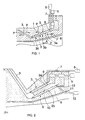
- Figure 3 shows a third extrusion apparatus according to the invention placed inside a corrugator.
- the reference numerals in Figure 3 correspond to those in Figures 1 and 2.
- the corrugator comprises chill moulds 14 that move forward and that have a grooved inner surface against which the plastic mass 15 is pressed in order to prepare a ribbed pipe. Since the structure of the corrugator is known per se, it will not be discussed in greater detail in this connection.
- the feeding device 8 and the actuator 5 for rotating the rotor 2 are placed at the back of the extrusion apparatus in such a way that they are positioned in the radial direction inside the outermost part of the feed gap 3, i.e. inside the outer circumference ⁇ u.
- the extrusion apparatus can then be placed inside the corrugator, and there is no need for long nozzles where the plastic mass 15 easily cools too much before arriving at the grooves of the chill moulds 14.
- the initial section of the rotor 2 has the shape of a tapering cone and the end section of the rotor has the shape of an expanding cone.
- the rotor 2 thus forms on each side separate feed gaps 3 that extend to the outer circumference ⁇ u of the extrusion apparatus.
- the rotor 2 comprises grooves 4 that transport the material to be extruded out from the extruder. However, at the end of the rotor 2 there is a smooth area comprising no grooves.
- the material to be extruded thus forms a smooth flow and comprises substantially no seams produced by the grooves. Further, the groove-free area produces and maintains a helical orientation field. This orientation is frozen into the product when the parison to be extruded meets the chill moulds.
- the extrusion apparatus further comprises a mandrel 18, and the plastic pipe is formed as the chill moulds 14 and the mandrel 18 press the plastic pipe preform from different sides.
- Figure 4 shows a detail of the apparatus of Figure 3.
- the reference numerals in Figure 4 correspond to those in Figures 1 to 3.
- Figure 4 shows clearly how the apparatus produces an opening 17 in the corrugated pipe.
- the plastic mass flows 15a and 15b are conducted in such a way that the plastic pipe to be extruded will comprise two layers.
- the opening 17 could be formed by means of blowing that is arranged to blow air or some other suitable gas through the rotor 2 in order to produce the opening 17.
- Figure 5 shows schematically an extrusion apparatus according to the invention placed in connection with an underground hole-making machine.
- the hole-making machine 20 is arranged to make a hole in the soil 21.
- the extrusion apparatus 19 in turn is arranged to move in connection with the hole-making machine 20 and to simultaneously produce a plastic pipe 22 in the hole made by the hole-making machine 20.
- the control and actuator connections 23 of the hole-making machine 20 can be made to pass through the hollow extrusion apparatus 19.
- Figure 5 does not show the means required for moving the hole-making machine 20 and the extrusion apparatus 19.
- Figure 6 shows a steel pipe which is coated with plastic from the inside and in which the layer situated against the steel 24 is thermally insulating adhesion plastic 25 and the second layer is cross-linked polyethylene, i.e. PEX 26.
- the adhesion plastic 25 can be for example grafted polyethylene.
- the adhesion plastic 25 is preferably foamed.
- the coating plastic is hot in the beginning so that its diameter remains large, whereas when the plastic cools the diameter of the plastic layer tends to decrease.
- the foamed adhesion plastic 25 sticks to the surface of the steel pipe but allows the inside to shrink. In such a case, the foam bubbles stretch in the radial direction, i.e.
- the foamed adhesion plastic 25 comprises preferably at least 10%, most preferably about 25%, of fine filling agent, such as calcium carbonate.
- the elastic modulus of the foam can thus be made high, i.e. the structure will be strong. Further, the foamed adhesion plastic 25 is a very good heat insulator against the PEX 26.
- the orientation of the plastic pressed inside can be frozen efficiently, since the steel pipe cools the pipe effectively from the outside.
- the cross-linked plastic sleeve 27 tends to return to the size of the diameter preceding the compression, and the expansion is provided by means of heating. The joint will then be extremely tight. It is also possible to use for the joint a sleeve 28 that is provided in the outside with mastic or some other adhesive with which the sleeve 28 can be made to stick to the pipe. Electrofusion can also be used. At the outside of the joint, it is possible to place a clamping collar 29 that is made of a strong material and that can be positioned to rest on a metal casing, such as steel 24. The clamping collar 29 receives axial tensile forces.
- the joint can also be implemented by welding, so that the adhesion plastic 25 acts as a good heat insulator against the innermost layer.
- the coating of steel pipes can be realized by applying the principle shown in Figure 5. Other metal pipes and concrete pipes can also be coated in a similar manner.
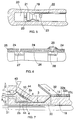
- Figure 7 is a cross-sectional side view of an extrusion apparatus according to the invention.
- the reference numerals in Figure 7 correspond to those of Figures 1 to 6.
- the extrusion apparatus of Figure 7 comprises one fixed stator, an intermediate stator 10. At the outside of the stator there is a rotatable outer rotor 2a and at the inside there is a rotatable inner rotor 2b.
- the surface of the intermediate stator 10 on the side of the outer rotor 2a is conical and correspondingly the surface of the outer rotor 2a on the side of the intermediate stator 10 is conical.
- the intermediate stator 10 comprises grooves 4 that transport the material to be extruded between the intermediate stator 10 and the outer rotor 2a out of the extrusion apparatus as the outer rotor 2a rotates.
- the inner rotor 2b comprises grooves that transport the plastic material to be extruded out of the extrusion apparatus as the inner rotor 2b rotates.
- the accompanying figure only shows an actuator 5 rotating the outer rotor 2a.
- the inner rotor 2b there may be one or several actuators.
- each rotor is rotated by the same pinion so that the rotors naturally rotate in opposite directions. If each rotor has its own actuator, the directions of rotation of the rotors can naturally be selected to be the same or opposite.
- the inner rotor 2b is followed by a rotatable expansion cone 30.
- the expansion cone 30 is rotated with a rotating means 31. With the rotating means 31 the expansion cone 30 can be rotated either at the same or a different speed with the inner rotor 2b in the same or different direction according to the desired orientation.
- the extrusion apparatus is arranged to prepare the innermost pipe of a multilayer pipe and the apparatus comprises means for producing the outer layer of the pipe, the means preparing the outer layer by winding a strip 32 spirally into a pipe. These means are not shown in the figure for the sake of clarity.
- the extrusion apparatus of Figure 7 makes the plastic mass 15 of the inner pipe move in a rotating manner so that the layers can be caused to stick together very well.
- the mandrel 18 may also be cooled, so that as the strip 32 and the mandrel 18 cool the plastic mass 15, the orientation of the mass can be frozen very efficiently.
- the strip 32 may be made of for example glass fibre or it may be a polypropylene strip oriented in one direction.
- the strip 32 preferably consists of an outer electrode layer 32a, an insulating layer 32b and an inner electrode layer 32c.
- the outer electrode layer 32a can be made of for example electrically conductive plastic or aluminium foil.
- the insulating layer 32b can be for example sintered or normal foamed plastic the cells of which comprise for example a filler.
- the foamed plastic is preferably contains holes so that for example air passes through it.
- the inner electrode layer 32c can have a similar structure as the outer electrode layer 32a.
- a potential difference can be created between the electrode layers, whereupon as the surface of the pipe is pressed in some place for example by a stone, the change in the potential difference of the insulating layers can be detected by a voltmeter.
- the application of the pipe is useful for example when laying the pipe in the ground, and for example problems caused by an excessive traffic load can be taken into account in such a situation. In the same way, it is possible to detect an excessive increase of the pressure inside the pipe.
- the alarm levels of the pipe can be determined easily by adjusting the outside ring stiffness of the pipe with respect to the inside stiffness and to the hardness of the foam.
- the pipe when used as a ventilation or a soil and waste pipe inside a building, noise of the sewer in the pipe can be detected and a counter-wave can be correspondingly produced in the outside to muffle the noise occurring in the pipe. Further, it is possible to use the outer surface to produce a sound, for example a warning signal.
- the potential difference between the electrode layers can also be used as a moisture barrier, so that water molecules cannot corrode the surface of the pipe.
- the insulating layer becomes damp, it affects the potential difference, wherefore the pipe can be used as a sensor for locating leakages for example in district heating pipes.
- the strength of the pipe is also excellent for example when aluminium is used for the electrode layer.
- the electrode layers can naturally be used for example for electrically heating or for locating the pipe, since for example aluminium can be easily detected from the ground by means of e.g. a metal detector.
- sound signals can also be supplied to the electrodes and the audible sound can be used to facilitate the location.
- the insulating or insulation foam layer situated between the electrodes can also be modified for example with carbon black so that it is partially conductive, whereupon the compression of the insulator directly affects for example the potential difference.
- the application for use in sprinklers is also possible since the fast warming of the metal foil affects the electric connection between the films.
- the pipe Due to its great strength originating from the combination of metal and oriented plastic and the possibilities of using alarm signals, the pipe is also applicable for offshore gas and oil pipes and for large trunk lines, for instance. It seems possible that by feeding high-frequency oscillation into a pair of electrodes, bacterial growth on the outer and/or inner surface of the pipe can be prevented.
- the electrode layers can be positioned in such a way that the outer electrode layer 32a is more rigid, whereupon the pipe reacts mainly to signals arriving from the inside, or in such a way that the inner electrode layer is more rigid, whereupon the pipe reacts mostly to signals from the outside.
- the apparatus of Figure 7 can also be arranged to rotate as a whole by mounting the extrusion apparatus in bearings from the end so that it rotates, whereupon for example the accumulation of tolerances can be avoided in the manufacture of films.
- the material of the tubular product comes out from the extruder rotating, and naturally the haul-off must be of rotating type too.
- the rotating cone 30 can be made axially movable, whereupon by changing the place of the rotating cone 30 it is possible to adjust the thickness of the inner layer of the material 15 to be extruded.
- the material flow can be adjusted by means of the feeding devices so that the material flows to be supplied to each side determine the thicknesses of the different layers.
- the outer rotor 2a, the inner rotor 2b and the expansion cone 30 preferably rotate in the same direction, whereupon the plastic material to be extruded is wound tightly together with the strip 32 to be supplied and the pipe to be extruded will form an even construction.
- the intermediate stator 10 comprises electric resistors 44, whereupon the material to be extruded can be heated mainly from the middle of the material through the intermediate stator 10, so that the heating can be realized effectively.
- Figure 8 shows a detail of the apparatus of Figure 7.
- the reference numerals in Figure 8 correspond to those in Figures 1 to 7.
- an aluminium strip 33 is supplied to form the outer layer.
- the aluminium strip 33 can be attached to the adjacent aluminium profile in the spiral formed by the strip for example by means of a continuous weld, spot welding or gluing or in some other manner known per se.
- the aluminium strip 33 may also comprise grooves as shown in Figure 8.
- the diameter ⁇ r of the outermost supply flow of the mass 15 to be supplied is made preferably greater than the smallest inner diameter ⁇ Al of the aluminium profile 33, whereupon the compression of the plastic mass 15 to the bottom of the grooves can be ensured and a very strong aluminium-coated plastic pipe can be manufactured.
- the profile can be of plastic material having e.g. a hollow square cross-section which will greatly enhance the ring stiffness of the pipe. This type of stiff pipe with an inside liner oriented with tensile strength can be used for example in pressure sewage applications.
- Figure 9 shows yet another application of an extrusion apparatus according to the invention.
- the reference numerals in Figure 9 correspond to those in Figures 1 to 8.
- a plastic layer is supplied by the extrusion apparatus 19 to the interior of the pipe to be made of the aluminium strip 33.
- a plastic layer 35 is then supplied on the aluminium pipe with a second extrusion apparatus that is conical.
- the pipe to be prepared is pulled with a pulling device 36 in such a way that the plastic layer supplied with the extrusion apparatus 34 sticks to the surface of the pipe at a distance from the extrusion apparatus 34.
- the pulling device 36 can be rotatably connected.
- the pulling of the pipe to be prepared succeeds, since due to the layer made of aluminium or some other metal, the pipe stands stretching well. Axial orientation is thus produced in the plastic layer 35.
- the extrusion apparatus 19 provides inside the aluminium pipe a plastic layer comprising a circumferential orientation.
- a pipe is thus obtained that comprises an aluminium layer and inside the aluminium layer there is a circumferentially and/or axially oriented plastic layer and outside there is an axially oriented plastic layer, wherefore the resulting pipe is very strong.
- FIG 10 schematically shows the use of an extrusion apparatus according to the invention for coating sewage pipes from the inside.
- the devices required can be installed underground for the interior coating of a sewage pipe 38 via a first drain pit 37a and a second drain pit 37b.
- the extrusion apparatus 19 is moved in the sewage pipe 38 by pulling it with a cable wire 39.
- the cable wire 39 is wound on a reel 40.
- the cable wire 39 is guided by means of control rolls 41.
- the extrusion apparatus 19 is first pulled by the cable wire 39 near the first drain pit 37a.
- the extrusion apparatus is then set into action to produce a plastic pipe 22 and it is pulled with the cable wire 39 towards the second drain pit 37b.
- the supply of the material and energy to the extrusion apparatus 19 can be realized along a duct 42 from a unit situated on the ground.
- the extrusion apparatus 19 can naturally also be placed in such a way that it prepares the plastic pipe 22 in the opposite direction as viewed in Figure 10.
- the extrusion apparatus comprises only one fixed stator and one rotatable rotor between which there is a conical feed gap.
- the method and the apparatus according to the invention can naturally also be used for preparing for example oriented films or high-pressure pipes or hoses.
Landscapes
- Engineering & Computer Science (AREA)
- Mechanical Engineering (AREA)
- General Engineering & Computer Science (AREA)
- Manufacturing & Machinery (AREA)
- Physics & Mathematics (AREA)
- Thermal Sciences (AREA)
- Chemical & Material Sciences (AREA)
- Composite Materials (AREA)
- General Physics & Mathematics (AREA)
- Extrusion Moulding Of Plastics Or The Like (AREA)
- Rigid Pipes And Flexible Pipes (AREA)
- Laminated Bodies (AREA)
- Sewage (AREA)
- Protection Of Pipes Against Damage, Friction, And Corrosion (AREA)
- Lining Or Joining Of Plastics Or The Like (AREA)
- Molding Of Porous Articles (AREA)
Claims (36)
- Appareil d'extrusion destiné au traitement d'un matériau plastique à extruder et à l'extrusion de produits creux, l'appareil d'extrusion comprenantcaractérisé en ce que le diamètre du trou d'alimentation (3) augmente de manière continue au moins sur une partie de sa longueur dans la direction de l'écoulement du matériau plastique à extruder.au moins un stator (1, 6, 10),au moins un rotor (2, 2a, 2b),au moins un trou d'alimentation en anneau (3) situé entre le stator (1, 6, 10) et le rotor (2, 2a, 2b) pour le matériau plastique à extruder, le diamètre du trou diminuant au moins en partie de manière continue dans la direction de l'écoulement du matériau plastique à extruder, le trou d'alimentation (3) étant sensiblement disposé en anneau dans l'appareil, etau moins un actionneur (5) destiné à faire tourner le rotor (2, 2a, 2b),
- Appareil d'extrusion selon la revendication 1, caractérisé en ce que le diamètre du trou d'alimentation (3) augmente immédiatement après le rotor (2, 2a, 2b).
- Appareil d'extrusion selon la revendication 1 ou 2, caractérisé en ce que le diamètre du trou d'alimentation (3) augmente linéairement.
- Appareil d'extrusion selon la revendication 1, 2 ou 3, caractérisé en ce que la partie d'extrémité du trou d'alimentation (3) a un diamètre constant.
- Appareil d'extrusion selon la revendication 1, 2 ou 3, caractérisé en ce que le trou d'alimentation (3) s'ouvre sur la circonférence extérieure (Φu) de l'appareil d'extrusion.
- Appareil d'extrusion selon la revendication 1, caractérisé en ce que l'actionneur (5) muni pour chaque rotor (2, 2a, 2b) de son dispositif d'entraínement du rotor (2, 2a, 2b) est placé à l'arrière de l'appareil d'extrusion de façon à ce qu'il soit situé dans la direction radiale de l'appareil d'extrusion à l'intérieur des contours déterminés par les autres composants de l'appareil d'extrusion.
- Appareil d'extrusion selon la revendication 6, dans lequel l'appareil d'extrusion est connecté de façon à fonctionner conjointement par exemple avec une machine à onduler utilisée pour préparer des tuyaux à nervures, caractérisé en ce que l'appareil d'extrusion est placé au moins en partie à l'intérieur de la machine à onduler.
- Appareil à extrusion selon l'une quelconque des revendications précédentes, caractérisé en ce que la partie initiale du rotor (2, 2a, 2b) a principalement la forme d'un cône effilé et la partie d'extrémité du rotor a principalement la forme d'un cône d'expansion.
- Appareil d'extrusion selon la revendication 8, caractérisé en ce que l'extrémité du rotor (2, 2a, 2b) comprend une région n'ayant sensiblement pas de gorges.
- Appareil à extrusion selon l'une quelconque des revendications précédentes, caractérisé en ce que l'appareil à extrusion comprend au moins un stator intermédiaire (10) possédant dans sa partie intérieure et dans sa partie extérieure au moins un rotor rotatif, et en ce que le stator intermédiaire possède des moyens permettant de chauffer le matériau à extruder depuis sa partie médiane.
- Appareil à extrusion selon l'une quelconque des revendications précédentes, caractérisé en ce que l'appareil à extrusion comprend un stator (1, 6, 10) dont au moins la surface extérieure est conique, un rotor extérieur rotatif (2a) placé à l'extérieur du stator et dont au moins la surface intérieure est conique, et un rotor intérieur rotatif (2b) placé à l'intérieur du stator, et en ce qu'un cône d'expansion rotatif (3) est relié au rotor intérieur (2b), la partie d'extrémité du trou d'alimentation (3) étant formée entre le rotor extérieur (2a) et le cône d'expansion (30).
- Appareil d'extrusion selon la revendication 11, caractérisé en ce que l'appareil d'extrusion possède des moyens d'alimentation permettant d'alimenter le stator (1, 6, 10) en matériau de manière séparée entre le rotor extérieur (2a) et le stator (1, 6, 10) et entre le rotor intérieur (2b) et le stator (1, 6, 10).
- Appareil d'extrusion selon la revendication 11 ou 12, caractérisé en ce que le cône d'expansion (30) est relié aux dispositifs de rotation (31) avec lesquels le cône d'expansion (30) peut être mis en rotation de manière indépendante du rotor intérieur (2b).
- Appareil d'extrusion selon l'une quelconque des revendications précédentes, caractérisé en ce que l'appareil d'extrusion est monté sur des paliers à l'arrière de l'appareil, ce qui permet de le faire tourner en un seul bloc.
- Utilisation d'un appareil d'extrusion selon la revendication 6 derrière une machine à trouer (20) qui est par exemple sous-terraine, dans laquelle l'appareil d'extrusion (19) est agencé pour produire un tuyau en plastique (22) dans le trou au sol fait par la machine.
- Utilisation d'un appareil d'extrusion selon la revendication 6 destinée à effectuer le revêtement de l'intérieur de nouveaux tuyaux en métal ou en béton.
- Utilisation d'un appareil d'extrusion selon la revendication 6 destinée à effectuer à nouveau le revêtement, depuis l'intérieur, d'un tuyau mis en place.
- Procédé d'extrusion dans lequel un produit creux est extrudé avec un appareil d'extrusion comprenant au moins un stator (1, 6, 10), au moins un rotor rotatif (2, 2a, 2b) qui est au moins en partie conique, dans lequel au moins la surface du stator (1, 6, 10) situé du côté du rotor (2, 2a, 2b) est conique au niveau de la partie conique du rotor (2, 2a, 2b), de sorte qu'il y a entre le stator (1, 6, 10) et le rotor (2, 2a, 2b) un trou d'alimentation en anneau dans lequel le matériau plastique à extruder est amené, trou d'alimentation (3) dont le diamètre diminue au moins en partie de manière continue dans la direction de l'écoulement du matériau plastique à extruder, le trou d'alimentation (3) étant sensiblement en anneau pour toute l'extrusion, caractérisé en ce que le diamètre du trou d'alimentation (3) augmente de manière continue au moins sur une partie de sa longueur dans la direction de l'écoulement du matériau plastique à extruder, le matériau plastique étant extrudé au moins sur une partie du trajet de sortie sous le contrôle du trou d'alimentation (3).
- Procédé selon la revendication 18, caractérisé en ce que le matériau à extruder est comprimé sur la circonférence extérieure (Φu) de l'appareil d'extrusion.
- Procédé selon la revendication 18 ou 19, caractérisé en ce que l'appareil d'extrusion comprend un stator (1, 6, 10) ayant au moins une surface extérieure qui est conique, un rotor extérieur rotatif (2a) placé à l'extérieur du stator et un rotor intérieur rotatif (2b) placé à l'intérieur du stator, et en ce qu'en liaison avec le rotor intérieur (2b), on fait tourner un cône d'expansion (30), le rotor extérieur (2a) et le cône d'expansion (30) constituant entre eux la partie d'extrémité du trou d'alimentation (3), le matériau s'écoulant dans le trou en tournant par l'action des rotors (2a, 2b) et du cône d'expansion (30).
- Procédé selon la revendication 20, caractérisé en ce qu'en réglant la position du rotor extérieur (2a) dans la direction radiale , l'épaisseur de la couche extérieure du matériau (15) à extruder est ajustée, et en déplaçant le cône (30) dans la direction axiale, l'épaisseur de la couche intérieure du matériau à extruder est ajustée.
- Procédé selon la revendication 20 ou 21, caractérisé en ce que le matériau à extruder est fourni séparément par des dispositifs d'alimentation séparés entre le stator (1, 6, 10) et le rotor extérieur (2a) et entre le stator (1, 6, 10) et le rotor intérieur (2b) et en ce que les propriétés des différents couches dans le produit à extruder sont ajustées en régulant la quantité de matériau qui s'écoule.
- Procédé selon l'une quelconque des revendications 20 à 22, caractérisé en ce que le matériau en plastique (15) à extruder est amené à l'intérieur du produit devant être revêtu d'une protection qui est formé juste avant le garnissage.
- Procédé selon la revendication 23, caractérisée en ce que le tuyau plastique destiné à former le revêtement est formé en même temps que le produit devant être revêtu d'une protection de façon à ce que le matériau du produit devant être revêtu d'une protection soit fourni au mandrin (18) afin que le mandrin (18) serve de point de support.
- Procédé selon la revendication 23 ou 24, caractérisé en ce que le produit devant être revêtu d'une protection est formé par une bande (32, 33) en enroulant la bande (32, 33) formant un tuyau sur le tuyau de protection.
- Procédé selon la revendication 25, caractérisé en ce que la bande (32, 33) à enrouler est rainurée, et en ce que le diamètre (Φr) de l'écoulement extérieur de matière (15) du matériau d'alimentation est supérieur au plus petit diamètre intérieur (ΦA1) du tuyau devant être formé au moyen de la bande (32, 33).
- Procédé selon l'une quelconque des revendications 21 à 26, caractérisé en ce au'une couche plastique (35) est formée sur le produit devant être revêtu d'une protection et en ce que le produit est simultanément tiré de façon à ce que la couche plastique (35) qui doit être fournie par l'appareil d'extrusion (34) se colle à la surface du tuyau à une certaine distance de l'appareil d'extrusion (34), de façon à obtenir une orientation axiale dans la couche plastique (35).
- Procédé selon l'une quelconque des revendications 18 à 20, caractérisé en ce que deux matériaux plastiques différents sont simultanément pressés contre la surface intérieure du tuyau, le plastic adhésif (25) étant pressé sur le tuyau et par exemple du polyéthylène réticulé (26) étant pressé sur le côté intérieur du plastique adhésif.
- Procédé selon la revendication 28, caractérisé en ce que le plastic adhésif (25) à presser est de type alvéolaire.
- Procédé selon la revendication 29, caractérisé en ce que le plastic adhésif (25) contient au moins 10%, de préférence environ 25%, d'agent de remplissage fin.
- Produit tubulaire constitué de différents matériaux au moyen d'un procédé selon la revendication 29, caractérisé en ce que la couche extérieure du produit est en métal ou en métal revêtu de plastique, à l'intérieur de laquelle il y a au moins une couche plastique, et entre la couche extérieure et au moins une couche plastique, il y a un plastique adhésif (25) qui est alvéolaire dans au moins une couche intermédiaire.
- Produit tubulaire selon la revendication 31, caractérisé en ce que le plastique adhésif (25) contient au moins 10%, de préférence environ 25%, d'agent de remplissage fin.
- Produit tubulaire selon la revendication 31 ou 32, caractérisé en ce que la couche intérieure du produit est constituée de plastique à orientation radiale et/ou axiale.
- Produit tubulaire selon l'une quelconque des revendications 31 à 33, caractérisé en ce que les bulles de mousse du plastique adhésif (25) sont orientées dans la direction radiale du tuyau.
- Produit tubulaire selon l'une quelconque des revendications 31 à 34, caractérisé en ce que le produit est raccordé à un autre produit similaire au moyen d'un manchon plastique réticulé (27) dont un diamètre est comprimé à une dimension inférieure à la normale.
- Produit tubulaire selon l'une quelconque des revendications 31 à 34, caractérisé en ce que le produit est raccordé à un autre produit similaire au moyen d'un manchon (28) situé à l'intérieur du joint et d'un collier de serrage (29) placé à l'extérieur du joint.
Priority Applications (2)
| Application Number | Priority Date | Filing Date | Title |
|---|---|---|---|
| EP19980200105 EP0853208B1 (fr) | 1995-06-26 | 1996-06-20 | Tube composite |
| EP19980200104 EP0844073B1 (fr) | 1995-06-26 | 1996-06-20 | Produit tubulaire, appareil et procédé d'extrusion |
Applications Claiming Priority (9)
| Application Number | Priority Date | Filing Date | Title |
|---|---|---|---|
| FI953162 | 1995-06-26 | ||
| FI953162A FI953162A0 (fi) | 1995-06-26 | 1995-06-26 | Extrusionanordning foer framstaellning av ett plastroer |
| SE9503272 | 1995-09-20 | ||
| SE9503272A SE521725C2 (sv) | 1995-09-20 | 1995-09-20 | Ihålig produkt av termoplastmaterial samt sätt för extrudering av densamma |
| FI961540 | 1996-04-04 | ||
| FI961540A FI103185B1 (fi) | 1996-04-04 | 1996-04-04 | Menetelmä suulakepuristettavan tuotteen ominaisuuksien säätämiseksi ja suulakepuristin |
| FI961822 | 1996-04-29 | ||
| FI961822A FI106005B (fi) | 1995-12-12 | 1996-04-29 | Menetelmä homogeenisen materiaalin tuottamiseksi suulakepuristimella ja suulakepuristin |
| PCT/FI1996/000359 WO1997001429A2 (fr) | 1995-06-26 | 1996-06-20 | Appareil et procede d'extrusion, produit tubulaire et tuyau |
Related Child Applications (2)
| Application Number | Title | Priority Date | Filing Date |
|---|---|---|---|
| EP19980200104 Division EP0844073B1 (fr) | 1995-06-26 | 1996-06-20 | Produit tubulaire, appareil et procédé d'extrusion |
| EP19980200105 Division EP0853208B1 (fr) | 1995-06-26 | 1996-06-20 | Tube composite |
Publications (2)
| Publication Number | Publication Date |
|---|---|
| EP0879131A2 EP0879131A2 (fr) | 1998-11-25 |
| EP0879131B1 true EP0879131B1 (fr) | 2001-03-14 |
Family
ID=27444248
Family Applications (3)
| Application Number | Title | Priority Date | Filing Date |
|---|---|---|---|
| EP96918716A Expired - Lifetime EP0879131B1 (fr) | 1995-06-26 | 1996-06-20 | Appareil et procede d'extrusion, produit tubulaire et tuyau |
| EP19980200104 Expired - Lifetime EP0844073B1 (fr) | 1995-06-26 | 1996-06-20 | Produit tubulaire, appareil et procédé d'extrusion |
| EP19980200105 Expired - Lifetime EP0853208B1 (fr) | 1995-06-26 | 1996-06-20 | Tube composite |
Family Applications After (2)
| Application Number | Title | Priority Date | Filing Date |
|---|---|---|---|
| EP19980200104 Expired - Lifetime EP0844073B1 (fr) | 1995-06-26 | 1996-06-20 | Produit tubulaire, appareil et procédé d'extrusion |
| EP19980200105 Expired - Lifetime EP0853208B1 (fr) | 1995-06-26 | 1996-06-20 | Tube composite |
Country Status (14)
| Country | Link |
|---|---|
| US (2) | US7381454B1 (fr) |
| EP (3) | EP0879131B1 (fr) |
| JP (3) | JP3390952B2 (fr) |
| KR (2) | KR100252137B1 (fr) |
| CN (1) | CN1061592C (fr) |
| AT (3) | ATE203589T1 (fr) |
| AU (1) | AU704944B2 (fr) |
| CA (3) | CA2233027C (fr) |
| DE (3) | DE69612118T2 (fr) |
| ES (2) | ES2178097T3 (fr) |
| IL (1) | IL122764A (fr) |
| RU (2) | RU2164318C2 (fr) |
| TR (1) | TR199701701T1 (fr) |
| WO (1) | WO1997001429A2 (fr) |
Cited By (1)
| Publication number | Priority date | Publication date | Assignee | Title |
|---|---|---|---|---|
| RU2401737C2 (ru) * | 2008-11-07 | 2010-10-20 | Евгений Владимирович Левин | Способ и установка для изготовления труб (варианты) |
Families Citing this family (26)
| Publication number | Priority date | Publication date | Assignee | Title |
|---|---|---|---|---|
| FI960768A0 (fi) * | 1996-02-20 | 1996-02-20 | Conenor Oy | Foerfarande och anordning foer att pressa plast i en form och en plastprodukt framstaelld med hjaelp av en form |
| DE19833885B4 (de) * | 1998-07-28 | 2006-10-05 | Bürger, Joachim, Curracloe-Kilmacoe | Verfahren zur Sanierung bzw. Renovierung von Abwasserleitungen und -kanälen |
| EP1306203A1 (fr) * | 2001-10-26 | 2003-05-02 | Atofina | Tube multicouche à base de polyamide, de polyester et d'aluminium |
| RU2296833C2 (ru) * | 2005-01-14 | 2007-04-10 | Открытое акционерное общество "Дальневосточная Горно-строительная Компания" | Способ прокладки водопропускной трубы под дорожной насыпью |
| EP2123367A1 (fr) * | 2008-05-21 | 2009-11-25 | Total Petrochemicals Research Feluy | Articles rotor en ligne |
| EP2213440A1 (fr) * | 2009-01-29 | 2010-08-04 | Brugg Rohr AG, Holding | Procédé de fabrication d'un conduit isolé thermiquement |
| DE102009037973A1 (de) | 2009-08-20 | 2011-02-24 | Egeplast Werner Strumann Gmbh & Co. Kg | Verfahren zur Überwachung von Leckagen |
| DE102009051603B4 (de) * | 2009-11-02 | 2011-09-22 | Dr. Mirtsch Gmbh | Verfahren zum Herstellen eines strukturierten Rohres, nach dem Verfahren hergestelltes strukturiertes Erzeugnis und Verwendung desselben |
| DE102009057857B4 (de) * | 2009-12-11 | 2014-02-20 | Carl Freudenberg Kg | Stiel für ein Reinigungsgerät |
| DE102011000432A1 (de) | 2011-02-01 | 2012-08-02 | Egeplast Werner Strumann Gmbh & Co. Kg | Kunststoffrohr oder Kunststoffrohrbündel |
| CN102601968B (zh) * | 2012-03-09 | 2014-06-11 | 天津市盈德意利保温材料有限公司 | 高密度聚乙烯外护套管生产工艺及外护套管模具 |
| WO2014143489A1 (fr) | 2013-03-11 | 2014-09-18 | Exxonmobil Upstream Research Company | Système de surveillance de revêtement de canalisation |
| CN103753749B (zh) * | 2014-02-11 | 2016-08-17 | 谢志树 | 一种大口径hdpe管的制造方法及其设备 |
| FR3029445B1 (fr) * | 2014-12-09 | 2017-09-29 | Fibroline France | Installation d'impregnation d'un support poreux comprenant des electrodes revetues optimisees |
| DE102016219303A1 (de) * | 2016-10-05 | 2018-04-05 | Zf Friedrichshafen Ag | Fahrwerksbauteil in Faserkunststoffverbund-Monobauweise mit duroplastischem Matrixwerkstoff und Verfahren zu dessen Herstellung |
| EP3477176A1 (fr) * | 2017-10-25 | 2019-05-01 | Evonik Degussa GmbH | Procédé de fabrication d'un tube revêtu d'une gaine intérieure |
| JP7011775B2 (ja) * | 2017-12-18 | 2022-01-27 | 日立金属株式会社 | 感圧センサの製造方法、及び感圧センサの製造装置 |
| DE102018102061B3 (de) * | 2018-01-30 | 2019-03-14 | Brandenburgische Technische Universität Cottbus-Senftenberg | Extrusionsvorrichtung und Verfahren zur Herstellung vonkohlefaserverstärkten Kunststoffhalbzeugen |
| FR3094487B1 (fr) * | 2019-03-28 | 2021-02-26 | Airbus Helicopters | Dispositif détecteur de dommages, véhicule et procédé de détection de dommage |
| CN112171989B (zh) * | 2019-07-05 | 2022-05-13 | 中国石油化工股份有限公司 | 一种用于温敏发泡材料的压缩定型装置 |
| EP3763943B1 (fr) | 2019-07-10 | 2024-09-04 | Grundfos Holding A/S | Procédé de fabrication d'une chemise d'entrefer |
| CN112644002B (zh) * | 2020-12-18 | 2022-05-27 | 常州市新创智能科技有限公司 | 一种复合材料自动辊压成型系统及其控制方法 |
| CN112664747B (zh) * | 2021-01-18 | 2022-07-05 | 临海市三江工程机械制造有限公司 | 一种能够抑制水锤影响的法兰防漏装置 |
| JP7528382B2 (ja) | 2021-03-04 | 2024-08-05 | クマール・カンダサミー | 連続的な塑性変形を生じさせるための処理および/もしくは機械、ならびに/またはそれによって製造される組成物および/もしくは製品 |
| WO2022187308A1 (fr) * | 2021-03-04 | 2022-09-09 | Kumar Kandasamy | Procédés et/ou machines pour produire une déformation plastique continue, et/ou compositions et/ou articles ainsi produits |
| KR102515294B1 (ko) * | 2021-09-16 | 2023-03-29 | 주식회사 세종플렉스 | 누수 알림기능을 갖는 pvc 호스 |
Family Cites Families (88)
| Publication number | Priority date | Publication date | Assignee | Title |
|---|---|---|---|---|
| DE372214C (de) | 1923-03-23 | Hermann Berstorff Maschb Ansta | Strangpresse fuer Gummi und aehnliche Massen | |
| DE579184C (de) * | 1931-04-08 | 1933-06-22 | Berthold Jenewein Dr Ing | Feuchtigkeitsanzeigevorrichtung fuer Isolierungen |
| US2691698A (en) * | 1950-10-26 | 1954-10-12 | Res Products Inc | Security telephone cable with jammer and alarm |
| GB848423A (en) * | 1957-03-12 | 1960-09-14 | Central Electr Generat Board | Improvements in or relating to tubular elements such as electric cables, pipes or the like adapted to be fluid-filled |
| DE1092186B (de) | 1958-03-07 | 1960-11-03 | Dynamit Nobel Ag | Schneckenpresse mit zwei konzentrisch ineinanderliegenden Pressraeumen zum Herstellen von Hohlprofilen aus thermoplastischem Kunststoff |
| BE615624A (fr) | 1961-05-10 | 1900-01-01 | ||
| NL298633A (fr) | 1962-10-11 | 1900-01-01 | ||
| FR1421522A (fr) * | 1964-11-04 | 1965-12-17 | Routiere De La Gironde Soc Chi | Conduite calorifugée utilisable pour le transport à grande distance des fuels |
| DE1454762A1 (de) | 1964-11-09 | 1969-05-08 | Barmag Barmer Maschf | Heissschmelze-Extruder |
| US3425455A (en) * | 1965-08-30 | 1969-02-04 | Exxon Research Engineering Co | Sprayed internally insulated pipe |
| US3721898A (en) * | 1968-12-04 | 1973-03-20 | P Dragoumis | Apparatus for detecting leakage from or rupture of pipes and other vessels containing fluid under pressure |
| CA930117A (en) * | 1969-10-20 | 1973-07-17 | E.I. Du Pont De Nemours And Company | Method of and apparatus for making a tube of plastic film |
| GB1310915A (en) * | 1969-12-16 | 1973-03-21 | Dunlop Holdings Ltd | Lined pipes |
| DE2051390A1 (de) | 1970-10-20 | 1972-04-27 | Ver Deutsche Metallwerke Ag | Verfahren zum kontinuierlichen Er zeugen von Rohren aus vernetzten Polyole fm Kunststoffen |
| GB1407043A (en) * | 1971-09-06 | 1975-09-24 | Sumitomo Metal Ind | Method of manufacturing coated steel pipes |
| US4015033A (en) | 1972-02-24 | 1977-03-29 | Imperial Chemical Industries Limited | Laminates of acrylonitrile/styrene copolymers |
| DE2308284A1 (de) * | 1973-02-20 | 1974-09-05 | Krupp Gmbh | Verfahren zur kontinuierlichen verarbeitung von kunststoffen oder elastomeren |
| SE428596B (sv) * | 1975-04-09 | 1983-07-11 | Raychem Corp | Anordning for hopkoppling av substrat exv ror omfattande ett organ av minnesmetall |
| JPS581379B2 (ja) * | 1974-10-08 | 1983-01-11 | ミズオチ シヨウケン | リユウタイケンチケ−ブル |
| DE2519705C2 (de) * | 1975-05-02 | 1982-03-18 | MFC Maschinenfabrik Chur AG, Chur | Vorrichtung zum Strangpressen von Rohren |
| US4025724A (en) * | 1975-08-12 | 1977-05-24 | Westinghouse Electric Corporation | Noise cancellation apparatus |
| GB1583758A (en) * | 1976-10-01 | 1981-02-04 | Nat Res Dev | Attenuation of sound waves in ducts |
| DE2725224A1 (de) * | 1977-06-03 | 1978-12-14 | Herbert Friedrich Ernst I Baum | Verfahren zur ununterbrochenen ueberwachung von unter druck stehenden rohrfernleitungen |
| US4171465A (en) * | 1978-08-08 | 1979-10-16 | National Research Development Corporation | Active control of sound waves |
| DE2841934A1 (de) * | 1978-09-27 | 1980-04-17 | Kabel Metallwerke Ghh | Waermeisoliertes leitungsrohr und verfahren zu seiner herstellung |
| US4429213A (en) * | 1978-10-20 | 1984-01-31 | Dayco Corporation | Electrically heated fluid conduit |
| US4277091A (en) * | 1979-04-19 | 1981-07-07 | Hunter John J | Coupling for lined pipe |
| FR2455972A1 (fr) * | 1979-05-10 | 1980-12-05 | Sogecan Ste Gle Canalisations | Procede et appareillage pour l'extrusion de tubes plastiques a parois composites |
| FR2463673A1 (fr) * | 1979-08-21 | 1981-02-27 | Ollivier Jean | Procede de fabrication d'un tube composite metal-matiere plastique et appareillage pour sa mise en oeuvre |
| US4438056A (en) * | 1980-07-07 | 1984-03-20 | Bethlehem Steel Corporation | Method for producing a corrugated pipe having a smooth lining of foam plastic |
| US4386629A (en) * | 1980-07-31 | 1983-06-07 | Raychem Corporation | Apparatus for internal pipe protection |
| NL8005255A (nl) | 1980-09-19 | 1982-04-16 | Wavin Bv | Kunststofbuisdeel voorzien van een kunststofschuimisolatielaag. |
| US4964440A (en) * | 1980-10-14 | 1990-10-23 | Andre James R | Ribbed pipe |
| JPS5827040A (ja) * | 1981-08-11 | 1983-02-17 | Sanwa Denki Seisakusho:Kk | 導電体被覆断熱管の短絡箇所探知方法 |
| US4535919A (en) * | 1981-08-19 | 1985-08-20 | Nordson Corporation | Hot melt adhesive system |
| US4554650A (en) * | 1982-04-02 | 1985-11-19 | The United States Of America As Represented By The Secretary Of The Navy | Oil filled towed array hose without couplings |
| US4523141A (en) * | 1982-04-16 | 1985-06-11 | The Kendall Company | Pipe coating |
| GB2120389A (en) * | 1982-04-28 | 1983-11-30 | Anthony John Maxwell | Monitoring lengths of hose |
| SE8206483L (sv) | 1982-11-15 | 1984-05-16 | Uponor Ab | Sett for orientering av materialet i ror av plast |
| DE3242271C2 (de) * | 1982-11-15 | 1986-03-20 | Adolf 7968 Saulgau Rundel | Mehrlagenrohr |
| US4640313A (en) * | 1983-12-19 | 1987-02-03 | Stanley Robert K | Interlining of pipelines for transporting sewage, water, slurries, liquid and gaseous hydrocarbons, and the like |
| FI67674C (fi) | 1984-02-24 | 1985-05-10 | Nokia Oy Ab | Dubbelextruder foer framstaellning av en tvaoskiktig roerformad extruderad produkt |
| DE3436774A1 (de) * | 1984-10-06 | 1986-04-10 | kabelmetal electro GmbH, 3000 Hannover | Flexibles leitungsrohr zum fortleiten fluessiger oder gasfoermiger medien |
| US4644977A (en) | 1985-03-25 | 1987-02-24 | The Gates Rubber Company | Hose with coextruded cover consisting of multiple foamed or nonfoamed layers |
| DE3511371A1 (de) * | 1985-03-28 | 1986-10-09 | Siemens AG, 1000 Berlin und 8000 München | Verfahren zur herstellung eines vernetzten schrumpfschlauches |
| DE3530187C2 (de) * | 1985-08-23 | 1994-12-01 | Marquet & Cie Noel | Verfahren und Vorrichtung zur Herstellung von thermisch isolierten Leitungsrohren |
| NL8502327A (nl) * | 1985-08-23 | 1987-03-16 | Wavin Bv | Kunststofbuis bestaande uit een buitenhuis met ribbels en gladde binnenwand, alsmede werkwijze voor het herstellen resp. verbeteren van een rioleringsbuis. |
| JPS62164400A (ja) * | 1986-01-14 | 1987-07-21 | Hitachi Plant Eng & Constr Co Ltd | 電子消音システム |
| AU588484B2 (en) * | 1986-06-26 | 1989-09-14 | General Electric Company | Modular extrusion head, method, intermediate product and product |
| WO1989006595A1 (fr) * | 1986-09-29 | 1989-07-27 | Sekisui Kagaku Kogyo Kabushiki Kaisha | Procede de production de conduites composites |
| US4846648A (en) * | 1986-11-19 | 1989-07-11 | American Maplan Corporation | Triple-wall foam coextrusion apparatus |
| US4870111A (en) * | 1987-02-24 | 1989-09-26 | Astro-Valcour, Incorporated | Moldable silane-crosslinked polyolefin foam beads |
| EP0372027B1 (fr) * | 1988-05-17 | 1993-12-22 | A. Käppeli's Söhne Ag | Procede de colmatage de canalisations endommagees |
| US5387386A (en) | 1988-06-06 | 1995-02-07 | Kirjavainen; Kari | Extrusion method and apparatus |
| FI83184C (fi) | 1988-06-06 | 1991-06-10 | Kari Kirjavainen | Foerfarande och extrusionsanordning foer att behandla material avsett att extruderas. |
| GB2223427B (en) * | 1988-08-03 | 1992-09-30 | Kitechnology Bv | Apparatus for forming plastics coated tube |
| US5119862A (en) * | 1988-10-31 | 1992-06-09 | Link-Pipe Technlogies, Inc. | Conduit repair apparatus |
| FR2650391B1 (fr) * | 1989-07-27 | 1993-07-16 | Durand Alain | Procede de fabrication ou de rehabilitation d'un reservoir de stockage, reservoirs obtenus |
| US5042532A (en) * | 1989-08-01 | 1991-08-27 | Cues, Inc. | Expandable tube apparatus for repairing pipelines |
| US5129428A (en) * | 1989-09-11 | 1992-07-14 | Dayco Products, Inc. | Flexible hose constuction |
| US5036210A (en) * | 1989-12-18 | 1991-07-30 | Gas Research Institute | Magnetically detectable plastic pipe |
| FR2659437B1 (fr) * | 1990-03-07 | 1994-03-25 | Caoutchouc Manufacture Plastique | Moyen de reperage lineaire de longueur, de vitesse ou de positionnement pour article souple de grande longeur. |
| US5096206A (en) * | 1990-06-01 | 1992-03-17 | W. E. Hall Company | Pipe joint sealer |
| DE4021664A1 (de) * | 1990-07-07 | 1992-01-16 | Wrede & Niedecken Verwaltung | Vorrichtung und verfahren zur ermittlung von leckagen an isolierten, ein stroemungsmedium beinhaltenden beziehungsweise fuehrenden bauteilen |
| US5104595A (en) * | 1990-07-13 | 1992-04-14 | Hunter Robert M | Process and apparatus for in situ rehabilitation of pipelines |
| US5270390A (en) | 1990-08-22 | 1993-12-14 | Kureha Kagaku Kogyo Kabushiki Kaisha | Resin composition and heat shrinkable film comprising the same composition layer |
| US5267670A (en) * | 1990-08-31 | 1993-12-07 | Dayco Products, Inc. | Fuel dispensing system having a flexible hose with a static dissipator and a fuel leak detector and method of making the same |
| DE4039757C2 (de) * | 1990-10-11 | 1994-02-03 | Heitkamp Gmbh E | Verfahren und Vorrichtung zur Herstellung von Rohren mit Innenauskleidung aus einem thermoplastischen Kunststoffmaterial |
| DE59009301D1 (de) * | 1990-11-13 | 1995-07-27 | Gerhard Rosenberg | Werkzeug zum Polyfusions-Verschweissen von extrudierten Kunststoff-Aluminium-Verbundrohren mit Fittings oder Formteilen. |
| US5396561A (en) * | 1990-11-14 | 1995-03-07 | Nelson Industries, Inc. | Active acoustic attenuation and spectral shaping system |
| DE69311403T2 (de) * | 1992-03-05 | 1997-12-04 | Nitta Moore Co Ltd | Brennstoffübertragendes Rohr |
| US5351720A (en) * | 1992-03-10 | 1994-10-04 | Link-Pipe, Inc. | Apparatus for repairing conduits |
| US5383087A (en) * | 1992-04-14 | 1995-01-17 | Itt Corporation | Multi-layer fuel and vapor tube |
| US5865218A (en) * | 1992-04-14 | 1999-02-02 | Itt Corporation | Multi-layer fuel and vapor tube |
| DE4225011B4 (de) * | 1992-07-29 | 2005-12-15 | Uponor Innovation Ab | Vorrichtung zum Herstellen eines Metall-Kunststoff-Verbundrohres |
| US5414213A (en) * | 1992-10-21 | 1995-05-09 | Hillburn; Ralph D. | Shielded electric cable |
| DE69431579T2 (de) * | 1993-08-03 | 2003-03-27 | Nitta Moore Co., Osaka | Kraftstofftransportschlauch |
| US5551484A (en) * | 1994-08-19 | 1996-09-03 | Charboneau; Kenneth R. | Pipe liner and monitoring system |
| AUPM903694A0 (en) * | 1994-10-25 | 1994-11-17 | Adams, Kevin | Multipurpose composite tubing |
| US5698210A (en) * | 1995-03-17 | 1997-12-16 | Lee County Mosquito Control District | Controlled delivery compositions and processes for treating organisms in a column of water or on land |
| BR9610557A (pt) * | 1995-09-20 | 1999-12-21 | Uponor Bv | Produtos poliméricos orientados |
| JP3736771B2 (ja) * | 1995-09-29 | 2006-01-18 | ローズマウント インコーポレイテッド | 浸食性液体搬送用の流体チューブ、その囲い構造、およびその製造方法 |
| US6170535B1 (en) * | 1998-11-17 | 2001-01-09 | Salflex Polymers Ltd. | Multi-layer conduit |
| US6386237B1 (en) * | 1999-04-12 | 2002-05-14 | The Goodyear Tire & Rubber Company | Abrasive material transport hose with wear detecting sensors |
| EP1044806B1 (fr) * | 1999-04-16 | 2006-05-24 | Ube Industries, Ltd. | Conduit de carburant multicouche |
| US6498991B1 (en) * | 1999-10-01 | 2002-12-24 | The Goodyear Tire & Rubber Company | Process and apparatus for monitoring a physical condition of a hose |
| US6305423B1 (en) * | 2000-06-05 | 2001-10-23 | Milliken & Company | Thermoplastic or thermoset pipes including conductive textile reinforcements for heating and leak detection purposes |
| ATE350573T1 (de) * | 2000-08-02 | 2007-01-15 | Ti Automotive Fuldabrueck Gmbh | Kraftfahrzeugrohrleitung |
-
1996
- 1996-06-20 EP EP96918716A patent/EP0879131B1/fr not_active Expired - Lifetime
- 1996-06-20 ES ES98200104T patent/ES2178097T3/es not_active Expired - Lifetime
- 1996-06-20 DE DE69612118T patent/DE69612118T2/de not_active Expired - Fee Related
- 1996-06-20 AU AU61285/96A patent/AU704944B2/en not_active Ceased
- 1996-06-20 KR KR1019970709725A patent/KR100252137B1/ko not_active Expired - Fee Related
- 1996-06-20 CN CN96195850A patent/CN1061592C/zh not_active Expired - Fee Related
- 1996-06-20 CA CA 2233027 patent/CA2233027C/fr not_active Expired - Fee Related
- 1996-06-20 AT AT98200105T patent/ATE203589T1/de active
- 1996-06-20 EP EP19980200104 patent/EP0844073B1/fr not_active Expired - Lifetime
- 1996-06-20 AT AT98200104T patent/ATE221455T1/de active
- 1996-06-20 EP EP19980200105 patent/EP0853208B1/fr not_active Expired - Lifetime
- 1996-06-20 TR TR97/01701T patent/TR199701701T1/xx unknown
- 1996-06-20 DE DE69614125T patent/DE69614125T2/de not_active Expired - Lifetime
- 1996-06-20 AT AT96918716T patent/ATE199675T1/de not_active IP Right Cessation
- 1996-06-20 KR KR1019980701608A patent/KR100253854B1/ko not_active Expired - Fee Related
- 1996-06-20 RU RU98101363A patent/RU2164318C2/ru not_active IP Right Cessation
- 1996-06-20 DE DE69622723T patent/DE69622723T2/de not_active Expired - Lifetime
- 1996-06-20 RU RU98101367A patent/RU2178354C2/ru not_active IP Right Cessation
- 1996-06-20 IL IL12276496A patent/IL122764A/en not_active IP Right Cessation
- 1996-06-20 ES ES96918716T patent/ES2157444T3/es not_active Expired - Lifetime
- 1996-06-20 WO PCT/FI1996/000359 patent/WO1997001429A2/fr not_active Ceased
- 1996-06-20 JP JP50418597A patent/JP3390952B2/ja not_active Expired - Fee Related
- 1996-06-20 CA CA 2233030 patent/CA2233030A1/fr not_active Abandoned
- 1996-06-20 CA CA 2225419 patent/CA2225419A1/fr not_active Abandoned
-
1997
- 1997-12-18 US US08/981,360 patent/US7381454B1/en not_active Expired - Fee Related
-
2000
- 2000-06-07 JP JP2000170797A patent/JP3345857B2/ja not_active Expired - Fee Related
- 2000-06-07 JP JP2000170787A patent/JP3519670B2/ja not_active Expired - Fee Related
-
2001
- 2001-11-08 US US10/010,440 patent/US7077164B2/en not_active Expired - Fee Related
Cited By (1)
| Publication number | Priority date | Publication date | Assignee | Title |
|---|---|---|---|---|
| RU2401737C2 (ru) * | 2008-11-07 | 2010-10-20 | Евгений Владимирович Левин | Способ и установка для изготовления труб (варианты) |
Also Published As
Similar Documents
| Publication | Publication Date | Title |
|---|---|---|
| EP0879131B1 (fr) | Appareil et procede d'extrusion, produit tubulaire et tuyau | |
| WO2008128571A2 (fr) | Tuyau composite multicouche sans raccord | |
| JP4420438B2 (ja) | チューブ状熱可塑性フィルムの縦方向延伸 | |
| WO2008142211A1 (fr) | Fabrication d'un élément de tubage et élément de tubage | |
| EA013854B1 (ru) | Способ и устройство для изготовления удлиненного изделия и изделие | |
| JP2000509132A (ja) | プラスチックマテリアルの圧力チューブ | |
| EP2113375A1 (fr) | Conduit de ventilation | |
| AU704144B2 (en) | A tubular product and an extrusion apparatus and method | |
| CN1078126C (zh) | 制造可挤出制品的方法和设备 | |
| CA2599159C (fr) | Procede pour la fabrication de tuyaux revetus | |
| WO2013160529A1 (fr) | Procédé de production de tube de plastique |
Legal Events
| Date | Code | Title | Description |
|---|---|---|---|
| PUAI | Public reference made under article 153(3) epc to a published international application that has entered the european phase |
Free format text: ORIGINAL CODE: 0009012 |
|
| 17P | Request for examination filed |
Effective date: 19980115 |
|
| AK | Designated contracting states |
Kind code of ref document: A2 Designated state(s): AT BE CH DE DK ES FI FR GB GR IE IT LI LU MC NL PT SE |
|
| RAP1 | Party data changed (applicant data changed or rights of an application transferred) |
Owner name: UPONOR INNOVATION AB |
|
| GRAG | Despatch of communication of intention to grant |
Free format text: ORIGINAL CODE: EPIDOS AGRA |
|
| 17Q | First examination report despatched |
Effective date: 20000516 |
|
| RAP1 | Party data changed (applicant data changed or rights of an application transferred) |
Owner name: UPONOR INNOVATION AB Owner name: NEXTROM HOLDING S.A. |
|
| GRAG | Despatch of communication of intention to grant |
Free format text: ORIGINAL CODE: EPIDOS AGRA |
|
| GRAH | Despatch of communication of intention to grant a patent |
Free format text: ORIGINAL CODE: EPIDOS IGRA |
|
| RAP1 | Party data changed (applicant data changed or rights of an application transferred) |
Owner name: NEXTROM HOLDING S.A. |
|
| GRAH | Despatch of communication of intention to grant a patent |
Free format text: ORIGINAL CODE: EPIDOS IGRA |
|
| GRAA | (expected) grant |
Free format text: ORIGINAL CODE: 0009210 |
|
| AK | Designated contracting states |
Kind code of ref document: B1 Designated state(s): AT BE CH DE DK ES FI FR GB GR IE IT LI LU MC NL PT SE |
|
| PG25 | Lapsed in a contracting state [announced via postgrant information from national office to epo] |
Ref country code: NL Free format text: LAPSE BECAUSE OF FAILURE TO SUBMIT A TRANSLATION OF THE DESCRIPTION OR TO PAY THE FEE WITHIN THE PRESCRIBED TIME-LIMIT Effective date: 20010314 Ref country code: BE Free format text: LAPSE BECAUSE OF FAILURE TO SUBMIT A TRANSLATION OF THE DESCRIPTION OR TO PAY THE FEE WITHIN THE PRESCRIBED TIME-LIMIT Effective date: 20010314 |
|
| REF | Corresponds to: |
Ref document number: 199675 Country of ref document: AT Date of ref document: 20010315 Kind code of ref document: T |
|
| REG | Reference to a national code |
Ref country code: CH Ref legal event code: EP |
|
| ITF | It: translation for a ep patent filed | ||
| REG | Reference to a national code |
Ref country code: CH Ref legal event code: NV Representative=s name: BOVARD AG PATENTANWAELTE |
|
| REG | Reference to a national code |
Ref country code: IE Ref legal event code: FG4D |
|
| REF | Corresponds to: |
Ref document number: 69612118 Country of ref document: DE Date of ref document: 20010419 |
|
| ET | Fr: translation filed | ||
| PG25 | Lapsed in a contracting state [announced via postgrant information from national office to epo] |
Ref country code: DK Free format text: LAPSE BECAUSE OF FAILURE TO SUBMIT A TRANSLATION OF THE DESCRIPTION OR TO PAY THE FEE WITHIN THE PRESCRIBED TIME-LIMIT Effective date: 20010614 |
|
| PG25 | Lapsed in a contracting state [announced via postgrant information from national office to epo] |
Ref country code: PT Free format text: LAPSE BECAUSE OF FAILURE TO SUBMIT A TRANSLATION OF THE DESCRIPTION OR TO PAY THE FEE WITHIN THE PRESCRIBED TIME-LIMIT Effective date: 20010615 Ref country code: GR Free format text: LAPSE BECAUSE OF FAILURE TO SUBMIT A TRANSLATION OF THE DESCRIPTION OR TO PAY THE FEE WITHIN THE PRESCRIBED TIME-LIMIT Effective date: 20010615 |
|
| PG25 | Lapsed in a contracting state [announced via postgrant information from national office to epo] |
Ref country code: LU Free format text: LAPSE BECAUSE OF NON-PAYMENT OF DUE FEES Effective date: 20010620 Ref country code: IE Free format text: LAPSE BECAUSE OF NON-PAYMENT OF DUE FEES Effective date: 20010620 |
|
| PG25 | Lapsed in a contracting state [announced via postgrant information from national office to epo] |
Ref country code: MC Free format text: LAPSE BECAUSE OF NON-PAYMENT OF DUE FEES Effective date: 20010630 |
|
| NLV1 | Nl: lapsed or annulled due to failure to fulfill the requirements of art. 29p and 29m of the patents act | ||
| REG | Reference to a national code |
Ref country code: ES Ref legal event code: FG2A Ref document number: 2157444 Country of ref document: ES Kind code of ref document: T3 |
|
| REG | Reference to a national code |
Ref country code: GB Ref legal event code: IF02 |
|
| PLBE | No opposition filed within time limit |
Free format text: ORIGINAL CODE: 0009261 |
|
| STAA | Information on the status of an ep patent application or granted ep patent |
Free format text: STATUS: NO OPPOSITION FILED WITHIN TIME LIMIT |
|
| 26N | No opposition filed | ||
| PGFP | Annual fee paid to national office [announced via postgrant information from national office to epo] |
Ref country code: FR Payment date: 20020530 Year of fee payment: 7 |
|
| PGFP | Annual fee paid to national office [announced via postgrant information from national office to epo] |
Ref country code: SE Payment date: 20020531 Year of fee payment: 7 Ref country code: AT Payment date: 20020531 Year of fee payment: 7 |
|
| PGFP | Annual fee paid to national office [announced via postgrant information from national office to epo] |
Ref country code: FI Payment date: 20020603 Year of fee payment: 7 Ref country code: CH Payment date: 20020603 Year of fee payment: 7 |
|
| PGFP | Annual fee paid to national office [announced via postgrant information from national office to epo] |
Ref country code: GB Payment date: 20020612 Year of fee payment: 7 |
|
| PGFP | Annual fee paid to national office [announced via postgrant information from national office to epo] |
Ref country code: DE Payment date: 20020620 Year of fee payment: 7 |
|
| PGFP | Annual fee paid to national office [announced via postgrant information from national office to epo] |
Ref country code: ES Payment date: 20020710 Year of fee payment: 7 |
|
| PG25 | Lapsed in a contracting state [announced via postgrant information from national office to epo] |
Ref country code: GB Free format text: LAPSE BECAUSE OF NON-PAYMENT OF DUE FEES Effective date: 20030620 Ref country code: FI Free format text: LAPSE BECAUSE OF NON-PAYMENT OF DUE FEES Effective date: 20030620 Ref country code: AT Free format text: LAPSE BECAUSE OF NON-PAYMENT OF DUE FEES Effective date: 20030620 |
|
| PG25 | Lapsed in a contracting state [announced via postgrant information from national office to epo] |
Ref country code: SE Free format text: LAPSE BECAUSE OF NON-PAYMENT OF DUE FEES Effective date: 20030621 Ref country code: ES Free format text: LAPSE BECAUSE OF NON-PAYMENT OF DUE FEES Effective date: 20030621 |
|
| PG25 | Lapsed in a contracting state [announced via postgrant information from national office to epo] |
Ref country code: LI Free format text: LAPSE BECAUSE OF NON-PAYMENT OF DUE FEES Effective date: 20030630 Ref country code: CH Free format text: LAPSE BECAUSE OF NON-PAYMENT OF DUE FEES Effective date: 20030630 |
|
| PG25 | Lapsed in a contracting state [announced via postgrant information from national office to epo] |
Ref country code: DE Free format text: LAPSE BECAUSE OF NON-PAYMENT OF DUE FEES Effective date: 20040101 |
|
| EUG | Se: european patent has lapsed | ||
| GBPC | Gb: european patent ceased through non-payment of renewal fee |
Effective date: 20030620 |
|
| REG | Reference to a national code |
Ref country code: CH Ref legal event code: PL |
|
| PG25 | Lapsed in a contracting state [announced via postgrant information from national office to epo] |
Ref country code: FR Free format text: LAPSE BECAUSE OF NON-PAYMENT OF DUE FEES Effective date: 20040227 |
|
| REG | Reference to a national code |
Ref country code: FR Ref legal event code: ST |
|
| REG | Reference to a national code |
Ref country code: ES Ref legal event code: FD2A Effective date: 20030621 |
|
| PG25 | Lapsed in a contracting state [announced via postgrant information from national office to epo] |
Ref country code: IT Free format text: LAPSE BECAUSE OF NON-PAYMENT OF DUE FEES;WARNING: LAPSES OF ITALIAN PATENTS WITH EFFECTIVE DATE BEFORE 2007 MAY HAVE OCCURRED AT ANY TIME BEFORE 2007. THE CORRECT EFFECTIVE DATE MAY BE DIFFERENT FROM THE ONE RECORDED. Effective date: 20050620 |