EP0879404B1 - Time-temperature integrating indicator device - Google Patents
Time-temperature integrating indicator device Download PDFInfo
- Publication number
- EP0879404B1 EP0879404B1 EP96912410A EP96912410A EP0879404B1 EP 0879404 B1 EP0879404 B1 EP 0879404B1 EP 96912410 A EP96912410 A EP 96912410A EP 96912410 A EP96912410 A EP 96912410A EP 0879404 B1 EP0879404 B1 EP 0879404B1
- Authority
- EP
- European Patent Office
- Prior art keywords
- porous matrix
- viscoelastic material
- indicator
- substrate
- viscoelastic
- Prior art date
- Legal status (The legal status is an assumption and is not a legal conclusion. Google has not performed a legal analysis and makes no representation as to the accuracy of the status listed.)
- Expired - Lifetime
Links
- 239000011159 matrix material Substances 0.000 claims description 240
- 239000003190 viscoelastic substance Substances 0.000 claims description 222
- 239000000758 substrate Substances 0.000 claims description 94
- 230000001186 cumulative effect Effects 0.000 claims description 50
- 230000005012 migration Effects 0.000 claims description 42
- 238000013508 migration Methods 0.000 claims description 42
- 239000004820 Pressure-sensitive adhesive Substances 0.000 claims description 40
- 125000006850 spacer group Chemical group 0.000 claims description 37
- 239000000203 mixture Substances 0.000 claims description 35
- 239000000853 adhesive Substances 0.000 claims description 33
- 230000001070 adhesive effect Effects 0.000 claims description 33
- DXPPIEDUBFUSEZ-UHFFFAOYSA-N 6-methylheptyl prop-2-enoate Chemical compound CC(C)CCCCCOC(=O)C=C DXPPIEDUBFUSEZ-UHFFFAOYSA-N 0.000 claims description 31
- 239000002245 particle Substances 0.000 claims description 29
- 230000004888 barrier function Effects 0.000 claims description 28
- 239000007788 liquid Substances 0.000 claims description 26
- 238000000034 method Methods 0.000 claims description 25
- 230000004913 activation Effects 0.000 claims description 24
- 230000008859 change Effects 0.000 claims description 23
- 239000011230 binding agent Substances 0.000 claims description 19
- NIXOWILDQLNWCW-UHFFFAOYSA-N 2-Propenoic acid Natural products OC(=O)C=C NIXOWILDQLNWCW-UHFFFAOYSA-N 0.000 claims description 18
- BAPJBEWLBFYGME-UHFFFAOYSA-N Methyl acrylate Chemical compound COC(=O)C=C BAPJBEWLBFYGME-UHFFFAOYSA-N 0.000 claims description 18
- -1 polypropylene Polymers 0.000 claims description 17
- SMZOUWXMTYCWNB-UHFFFAOYSA-N 2-(2-methoxy-5-methylphenyl)ethanamine Chemical compound COC1=CC=C(C)C=C1CCN SMZOUWXMTYCWNB-UHFFFAOYSA-N 0.000 claims description 15
- 230000003287 optical effect Effects 0.000 claims description 15
- VYPSYNLAJGMNEJ-UHFFFAOYSA-N Silicium dioxide Chemical compound O=[Si]=O VYPSYNLAJGMNEJ-UHFFFAOYSA-N 0.000 claims description 14
- 230000003213 activating effect Effects 0.000 claims description 13
- 239000004014 plasticizer Substances 0.000 claims description 12
- 230000004044 response Effects 0.000 claims description 11
- 239000005871 repellent Substances 0.000 claims description 9
- 230000002940 repellent Effects 0.000 claims description 9
- VTYYLEPIZMXCLO-UHFFFAOYSA-L Calcium carbonate Chemical compound [Ca+2].[O-]C([O-])=O VTYYLEPIZMXCLO-UHFFFAOYSA-L 0.000 claims description 8
- NIXOWILDQLNWCW-UHFFFAOYSA-M Acrylate Chemical compound [O-]C(=O)C=C NIXOWILDQLNWCW-UHFFFAOYSA-M 0.000 claims description 7
- 230000007423 decrease Effects 0.000 claims description 7
- 239000000377 silicon dioxide Substances 0.000 claims description 7
- PSGCQDPCAWOCSH-UHFFFAOYSA-N (4,7,7-trimethyl-3-bicyclo[2.2.1]heptanyl) prop-2-enoate Chemical compound C1CC2(C)C(OC(=O)C=C)CC1C2(C)C PSGCQDPCAWOCSH-UHFFFAOYSA-N 0.000 claims description 5
- 239000004215 Carbon black (E152) Substances 0.000 claims description 4
- JIGUQPWFLRLWPJ-UHFFFAOYSA-N Ethyl acrylate Chemical compound CCOC(=O)C=C JIGUQPWFLRLWPJ-UHFFFAOYSA-N 0.000 claims description 4
- GWEVSGVZZGPLCZ-UHFFFAOYSA-N Titan oxide Chemical compound O=[Ti]=O GWEVSGVZZGPLCZ-UHFFFAOYSA-N 0.000 claims description 4
- XLOMVQKBTHCTTD-UHFFFAOYSA-N Zinc monoxide Chemical compound [Zn]=O XLOMVQKBTHCTTD-UHFFFAOYSA-N 0.000 claims description 4
- 229910000019 calcium carbonate Inorganic materials 0.000 claims description 4
- 239000011521 glass Substances 0.000 claims description 4
- 229930195733 hydrocarbon Natural products 0.000 claims description 4
- 150000002430 hydrocarbons Chemical class 0.000 claims description 4
- PNJWIWWMYCMZRO-UHFFFAOYSA-N pent‐4‐en‐2‐one Natural products CC(=O)CC=C PNJWIWWMYCMZRO-UHFFFAOYSA-N 0.000 claims description 4
- 229920001296 polysiloxane Polymers 0.000 claims description 4
- RSWGJHLUYNHPMX-UHFFFAOYSA-N Abietic-Saeure Natural products C12CCC(C(C)C)=CC2=CCC2C1(C)CCCC2(C)C(O)=O RSWGJHLUYNHPMX-UHFFFAOYSA-N 0.000 claims description 3
- MXRIRQGCELJRSN-UHFFFAOYSA-N O.O.O.[Al] Chemical compound O.O.O.[Al] MXRIRQGCELJRSN-UHFFFAOYSA-N 0.000 claims description 3
- 239000005062 Polybutadiene Substances 0.000 claims description 3
- KHPCPRHQVVSZAH-HUOMCSJISA-N Rosin Natural products O(C/C=C/c1ccccc1)[C@H]1[C@H](O)[C@@H](O)[C@@H](O)[C@@H](CO)O1 KHPCPRHQVVSZAH-HUOMCSJISA-N 0.000 claims description 3
- WUKWITHWXAAZEY-UHFFFAOYSA-L calcium difluoride Chemical compound [F-].[F-].[Ca+2] WUKWITHWXAAZEY-UHFFFAOYSA-L 0.000 claims description 3
- 229910001634 calcium fluoride Inorganic materials 0.000 claims description 3
- 150000002148 esters Chemical class 0.000 claims description 3
- 239000003921 oil Substances 0.000 claims description 3
- 229920002857 polybutadiene Polymers 0.000 claims description 3
- 235000012239 silicon dioxide Nutrition 0.000 claims description 3
- KHPCPRHQVVSZAH-UHFFFAOYSA-N trans-cinnamyl beta-D-glucopyranoside Natural products OC1C(O)C(O)C(CO)OC1OCC=CC1=CC=CC=C1 KHPCPRHQVVSZAH-UHFFFAOYSA-N 0.000 claims description 3
- 239000004593 Epoxy Substances 0.000 claims description 2
- 229920002367 Polyisobutene Polymers 0.000 claims description 2
- 239000004743 Polypropylene Substances 0.000 claims description 2
- BLRPTPMANUNPDV-UHFFFAOYSA-N Silane Chemical compound [SiH4] BLRPTPMANUNPDV-UHFFFAOYSA-N 0.000 claims description 2
- 229920000180 alkyd Polymers 0.000 claims description 2
- DQXBYHZEEUGOBF-UHFFFAOYSA-N but-3-enoic acid;ethene Chemical compound C=C.OC(=O)CC=C DQXBYHZEEUGOBF-UHFFFAOYSA-N 0.000 claims description 2
- 239000005038 ethylene vinyl acetate Substances 0.000 claims description 2
- 239000002480 mineral oil Substances 0.000 claims description 2
- 235000010446 mineral oil Nutrition 0.000 claims description 2
- TWNQGVIAIRXVLR-UHFFFAOYSA-N oxo(oxoalumanyloxy)alumane Chemical compound O=[Al]O[Al]=O TWNQGVIAIRXVLR-UHFFFAOYSA-N 0.000 claims description 2
- 229920001200 poly(ethylene-vinyl acetate) Polymers 0.000 claims description 2
- 229920001195 polyisoprene Polymers 0.000 claims description 2
- 229920001155 polypropylene Polymers 0.000 claims description 2
- 229920002635 polyurethane Polymers 0.000 claims description 2
- 239000004814 polyurethane Substances 0.000 claims description 2
- 239000011148 porous material Substances 0.000 claims description 2
- 229940100486 rice starch Drugs 0.000 claims description 2
- 229910000077 silane Inorganic materials 0.000 claims description 2
- 229920001187 thermosetting polymer Polymers 0.000 claims description 2
- 239000004408 titanium dioxide Substances 0.000 claims description 2
- 239000011787 zinc oxide Substances 0.000 claims description 2
- VVUXLKACYYLEIW-UHFFFAOYSA-N 6-methylheptyl prop-2-enoate;2-methylprop-2-enoic acid Chemical compound CC(=C)C(O)=O.CC(C)CCCCCOC(=O)C=C VVUXLKACYYLEIW-UHFFFAOYSA-N 0.000 claims 1
- 229920005822 acrylic binder Polymers 0.000 claims 1
- 239000011345 viscous material Substances 0.000 claims 1
- 239000010408 film Substances 0.000 description 46
- XEKOWRVHYACXOJ-UHFFFAOYSA-N Ethyl acetate Chemical compound CCOC(C)=O XEKOWRVHYACXOJ-UHFFFAOYSA-N 0.000 description 30
- 239000000463 material Substances 0.000 description 30
- 238000000576 coating method Methods 0.000 description 26
- 239000011248 coating agent Substances 0.000 description 25
- 239000007787 solid Substances 0.000 description 22
- KFZMGEQAYNKOFK-UHFFFAOYSA-N Isopropanol Chemical compound CC(C)O KFZMGEQAYNKOFK-UHFFFAOYSA-N 0.000 description 14
- 239000010410 layer Substances 0.000 description 12
- 230000015556 catabolic process Effects 0.000 description 11
- 238000006731 degradation reaction Methods 0.000 description 11
- 235000019439 ethyl acetate Nutrition 0.000 description 11
- 230000009477 glass transition Effects 0.000 description 10
- 239000000178 monomer Substances 0.000 description 10
- YXFVVABEGXRONW-UHFFFAOYSA-N Toluene Chemical compound CC1=CC=CC=C1 YXFVVABEGXRONW-UHFFFAOYSA-N 0.000 description 9
- 235000013305 food Nutrition 0.000 description 9
- 239000002904 solvent Substances 0.000 description 9
- 239000012530 fluid Substances 0.000 description 8
- 230000035882 stress Effects 0.000 description 8
- 239000004698 Polyethylene Substances 0.000 description 7
- 229920000573 polyethylene Polymers 0.000 description 7
- 230000000007 visual effect Effects 0.000 description 7
- 239000012190 activator Substances 0.000 description 6
- 238000004519 manufacturing process Methods 0.000 description 6
- 239000000123 paper Substances 0.000 description 6
- 230000003466 anti-cipated effect Effects 0.000 description 5
- 238000010276 construction Methods 0.000 description 5
- 229920001577 copolymer Polymers 0.000 description 5
- 230000000694 effects Effects 0.000 description 5
- 238000007639 printing Methods 0.000 description 5
- 238000012360 testing method Methods 0.000 description 5
- IJGRMHOSHXDMSA-UHFFFAOYSA-N Atomic nitrogen Chemical compound N#N IJGRMHOSHXDMSA-UHFFFAOYSA-N 0.000 description 4
- 125000005250 alkyl acrylate group Chemical group 0.000 description 4
- 238000006243 chemical reaction Methods 0.000 description 4
- HBGGXOJOCNVPFY-UHFFFAOYSA-N diisononyl phthalate Chemical compound CC(C)CCCCCCOC(=O)C1=CC=CC=C1C(=O)OCCCCCCC(C)C HBGGXOJOCNVPFY-UHFFFAOYSA-N 0.000 description 4
- 239000006185 dispersion Substances 0.000 description 4
- 239000003814 drug Substances 0.000 description 4
- 230000010354 integration Effects 0.000 description 4
- 239000002655 kraft paper Substances 0.000 description 4
- 239000000155 melt Substances 0.000 description 4
- 229920000642 polymer Polymers 0.000 description 4
- 230000002829 reductive effect Effects 0.000 description 4
- 239000004925 Acrylic resin Substances 0.000 description 3
- 229920000178 Acrylic resin Polymers 0.000 description 3
- 230000009471 action Effects 0.000 description 3
- 238000004026 adhesive bonding Methods 0.000 description 3
- 239000012790 adhesive layer Substances 0.000 description 3
- 229910052782 aluminium Inorganic materials 0.000 description 3
- XAGFODPZIPBFFR-UHFFFAOYSA-N aluminium Chemical compound [Al] XAGFODPZIPBFFR-UHFFFAOYSA-N 0.000 description 3
- 229920006378 biaxially oriented polypropylene Polymers 0.000 description 3
- 239000011127 biaxially oriented polypropylene Substances 0.000 description 3
- 125000004432 carbon atom Chemical group C* 0.000 description 3
- 238000003851 corona treatment Methods 0.000 description 3
- 230000001419 dependent effect Effects 0.000 description 3
- 229920001971 elastomer Polymers 0.000 description 3
- 238000002474 experimental method Methods 0.000 description 3
- 238000011049 filling Methods 0.000 description 3
- 239000003999 initiator Substances 0.000 description 3
- 238000010030 laminating Methods 0.000 description 3
- 238000002844 melting Methods 0.000 description 3
- 230000008018 melting Effects 0.000 description 3
- 238000005065 mining Methods 0.000 description 3
- 238000002156 mixing Methods 0.000 description 3
- 229910052757 nitrogen Inorganic materials 0.000 description 3
- 230000000149 penetrating effect Effects 0.000 description 3
- 238000003825 pressing Methods 0.000 description 3
- 229920005989 resin Polymers 0.000 description 3
- 239000011347 resin Substances 0.000 description 3
- 238000003860 storage Methods 0.000 description 3
- 239000000126 substance Substances 0.000 description 3
- 230000007704 transition Effects 0.000 description 3
- 238000011282 treatment Methods 0.000 description 3
- 229960005486 vaccine Drugs 0.000 description 3
- XLYOFNOQVPJJNP-UHFFFAOYSA-N water Substances O XLYOFNOQVPJJNP-UHFFFAOYSA-N 0.000 description 3
- QWDQYHPOSSHSAW-UHFFFAOYSA-N 1-isocyanatooctadecane Chemical compound CCCCCCCCCCCCCCCCCCN=C=O QWDQYHPOSSHSAW-UHFFFAOYSA-N 0.000 description 2
- NLHHRLWOUZZQLW-UHFFFAOYSA-N Acrylonitrile Chemical compound C=CC#N NLHHRLWOUZZQLW-UHFFFAOYSA-N 0.000 description 2
- 229920002799 BoPET Polymers 0.000 description 2
- MQIUGAXCHLFZKX-UHFFFAOYSA-N Di-n-octyl phthalate Natural products CCCCCCCCOC(=O)C1=CC=CC=C1C(=O)OCCCCCCCC MQIUGAXCHLFZKX-UHFFFAOYSA-N 0.000 description 2
- 239000005057 Hexamethylene diisocyanate Substances 0.000 description 2
- 230000005483 Hooke's law Effects 0.000 description 2
- 239000004372 Polyvinyl alcohol Substances 0.000 description 2
- PPBRXRYQALVLMV-UHFFFAOYSA-N Styrene Chemical compound C=CC1=CC=CC=C1 PPBRXRYQALVLMV-UHFFFAOYSA-N 0.000 description 2
- 238000004458 analytical method Methods 0.000 description 2
- 239000012620 biological material Substances 0.000 description 2
- BJQHLKABXJIVAM-UHFFFAOYSA-N bis(2-ethylhexyl) phthalate Chemical compound CCCCC(CC)COC(=O)C1=CC=CC=C1C(=O)OCC(CC)CCCC BJQHLKABXJIVAM-UHFFFAOYSA-N 0.000 description 2
- 229920002678 cellulose Polymers 0.000 description 2
- 229920006217 cellulose acetate butyrate Polymers 0.000 description 2
- 239000002415 cerumenolytic agent Substances 0.000 description 2
- 239000003795 chemical substances by application Substances 0.000 description 2
- 239000003086 colorant Substances 0.000 description 2
- 239000002537 cosmetic Substances 0.000 description 2
- 238000007766 curtain coating Methods 0.000 description 2
- 229940079593 drug Drugs 0.000 description 2
- 238000001035 drying Methods 0.000 description 2
- 239000013013 elastic material Substances 0.000 description 2
- 230000006355 external stress Effects 0.000 description 2
- 239000007789 gas Substances 0.000 description 2
- RRAMGCGOFNQTLD-UHFFFAOYSA-N hexamethylene diisocyanate Chemical compound O=C=NCCCCCCN=C=O RRAMGCGOFNQTLD-UHFFFAOYSA-N 0.000 description 2
- 229920001903 high density polyethylene Polymers 0.000 description 2
- 239000004700 high-density polyethylene Substances 0.000 description 2
- 229920001519 homopolymer Polymers 0.000 description 2
- 125000004356 hydroxy functional group Chemical group O* 0.000 description 2
- PBOSTUDLECTMNL-UHFFFAOYSA-N lauryl acrylate Chemical compound CCCCCCCCCCCCOC(=O)C=C PBOSTUDLECTMNL-UHFFFAOYSA-N 0.000 description 2
- 238000005259 measurement Methods 0.000 description 2
- 230000000813 microbial effect Effects 0.000 description 2
- 238000012544 monitoring process Methods 0.000 description 2
- 239000011101 paper laminate Substances 0.000 description 2
- 230000000737 periodic effect Effects 0.000 description 2
- 229920003023 plastic Polymers 0.000 description 2
- 239000004033 plastic Substances 0.000 description 2
- 229920001084 poly(chloroprene) Polymers 0.000 description 2
- 229920006267 polyester film Polymers 0.000 description 2
- 238000006116 polymerization reaction Methods 0.000 description 2
- 229920000346 polystyrene-polyisoprene block-polystyrene Polymers 0.000 description 2
- 229920002451 polyvinyl alcohol Polymers 0.000 description 2
- 235000019422 polyvinyl alcohol Nutrition 0.000 description 2
- 238000011002 quantification Methods 0.000 description 2
- 230000003014 reinforcing effect Effects 0.000 description 2
- 230000002441 reversible effect Effects 0.000 description 2
- 239000006104 solid solution Substances 0.000 description 2
- 239000000243 solution Substances 0.000 description 2
- JWYVGKFDLWWQJX-UHFFFAOYSA-N 1-ethenylazepan-2-one Chemical compound C=CN1CCCCCC1=O JWYVGKFDLWWQJX-UHFFFAOYSA-N 0.000 description 1
- OZAIFHULBGXAKX-UHFFFAOYSA-N 2-(2-cyanopropan-2-yldiazenyl)-2-methylpropanenitrile Chemical compound N#CC(C)(C)N=NC(C)(C)C#N OZAIFHULBGXAKX-UHFFFAOYSA-N 0.000 description 1
- GOXQRTZXKQZDDN-UHFFFAOYSA-N 2-Ethylhexyl acrylate Chemical compound CCCCC(CC)COC(=O)C=C GOXQRTZXKQZDDN-UHFFFAOYSA-N 0.000 description 1
- CUXGDKOCSSIRKK-UHFFFAOYSA-N 7-methyloctyl prop-2-enoate Chemical compound CC(C)CCCCCCOC(=O)C=C CUXGDKOCSSIRKK-UHFFFAOYSA-N 0.000 description 1
- 108010011485 Aspartame Proteins 0.000 description 1
- KCKDFIJGPQNRRZ-UHFFFAOYSA-N CC(CCC1)C1C1CC1 Chemical compound CC(CCC1)C1C1CC1 KCKDFIJGPQNRRZ-UHFFFAOYSA-N 0.000 description 1
- OYPRJOBELJOOCE-UHFFFAOYSA-N Calcium Chemical compound [Ca] OYPRJOBELJOOCE-UHFFFAOYSA-N 0.000 description 1
- 229920000298 Cellophane Polymers 0.000 description 1
- JOYRKODLDBILNP-UHFFFAOYSA-N Ethyl urethane Chemical compound CCOC(N)=O JOYRKODLDBILNP-UHFFFAOYSA-N 0.000 description 1
- 244000043261 Hevea brasiliensis Species 0.000 description 1
- OWYWGLHRNBIFJP-UHFFFAOYSA-N Ipazine Chemical compound CCN(CC)C1=NC(Cl)=NC(NC(C)C)=N1 OWYWGLHRNBIFJP-UHFFFAOYSA-N 0.000 description 1
- CERQOIWHTDAKMF-UHFFFAOYSA-M Methacrylate Chemical compound CC(=C)C([O-])=O CERQOIWHTDAKMF-UHFFFAOYSA-M 0.000 description 1
- CERQOIWHTDAKMF-UHFFFAOYSA-N Methacrylic acid Chemical class CC(=C)C(O)=O CERQOIWHTDAKMF-UHFFFAOYSA-N 0.000 description 1
- NTIZESTWPVYFNL-UHFFFAOYSA-N Methyl isobutyl ketone Chemical compound CC(C)CC(C)=O NTIZESTWPVYFNL-UHFFFAOYSA-N 0.000 description 1
- UIHCLUNTQKBZGK-UHFFFAOYSA-N Methyl isobutyl ketone Natural products CCC(C)C(C)=O UIHCLUNTQKBZGK-UHFFFAOYSA-N 0.000 description 1
- WHNWPMSKXPGLAX-UHFFFAOYSA-N N-Vinyl-2-pyrrolidone Chemical compound C=CN1CCCC1=O WHNWPMSKXPGLAX-UHFFFAOYSA-N 0.000 description 1
- 239000004677 Nylon Substances 0.000 description 1
- 241000220317 Rosa Species 0.000 description 1
- 239000004809 Teflon Substances 0.000 description 1
- 229920006362 Teflon® Polymers 0.000 description 1
- 239000002253 acid Substances 0.000 description 1
- 150000003926 acrylamides Chemical class 0.000 description 1
- 125000000217 alkyl group Chemical group 0.000 description 1
- 125000005233 alkylalcohol group Chemical group 0.000 description 1
- 239000003963 antioxidant agent Substances 0.000 description 1
- 239000000605 aspartame Substances 0.000 description 1
- IAOZJIPTCAWIRG-QWRGUYRKSA-N aspartame Chemical compound OC(=O)C[C@H](N)C(=O)N[C@H](C(=O)OC)CC1=CC=CC=C1 IAOZJIPTCAWIRG-QWRGUYRKSA-N 0.000 description 1
- 229960003438 aspartame Drugs 0.000 description 1
- 235000010357 aspartame Nutrition 0.000 description 1
- 230000008901 benefit Effects 0.000 description 1
- 229920001400 block copolymer Polymers 0.000 description 1
- CQEYYJKEWSMYFG-UHFFFAOYSA-N butyl acrylate Chemical compound CCCCOC(=O)C=C CQEYYJKEWSMYFG-UHFFFAOYSA-N 0.000 description 1
- 229920005549 butyl rubber Polymers 0.000 description 1
- 239000011575 calcium Substances 0.000 description 1
- 229910052791 calcium Inorganic materials 0.000 description 1
- 238000003490 calendering Methods 0.000 description 1
- 239000001913 cellulose Substances 0.000 description 1
- 239000000919 ceramic Substances 0.000 description 1
- 235000013339 cereals Nutrition 0.000 description 1
- 238000013329 compounding Methods 0.000 description 1
- 150000001875 compounds Chemical class 0.000 description 1
- 238000011109 contamination Methods 0.000 description 1
- 239000002178 crystalline material Substances 0.000 description 1
- 230000003247 decreasing effect Effects 0.000 description 1
- FWLDHHJLVGRRHD-UHFFFAOYSA-N decyl prop-2-enoate Chemical compound CCCCCCCCCCOC(=O)C=C FWLDHHJLVGRRHD-UHFFFAOYSA-N 0.000 description 1
- 230000000994 depressogenic effect Effects 0.000 description 1
- 238000009792 diffusion process Methods 0.000 description 1
- KPUWHANPEXNPJT-UHFFFAOYSA-N disiloxane Chemical class [SiH3]O[SiH3] KPUWHANPEXNPJT-UHFFFAOYSA-N 0.000 description 1
- 239000000806 elastomer Substances 0.000 description 1
- 239000000839 emulsion Substances 0.000 description 1
- 230000007613 environmental effect Effects 0.000 description 1
- 230000002255 enzymatic effect Effects 0.000 description 1
- 238000001125 extrusion Methods 0.000 description 1
- 239000004744 fabric Substances 0.000 description 1
- 230000009969 flowable effect Effects 0.000 description 1
- 239000006260 foam Substances 0.000 description 1
- 239000011888 foil Substances 0.000 description 1
- 235000013373 food additive Nutrition 0.000 description 1
- 239000002778 food additive Substances 0.000 description 1
- 230000008014 freezing Effects 0.000 description 1
- 238000007710 freezing Methods 0.000 description 1
- 235000013611 frozen food Nutrition 0.000 description 1
- 239000011086 glassine Substances 0.000 description 1
- 230000005484 gravity Effects 0.000 description 1
- 239000011084 greaseproof paper Substances 0.000 description 1
- LNMQRPPRQDGUDR-UHFFFAOYSA-N hexyl prop-2-enoate Chemical compound CCCCCCOC(=O)C=C LNMQRPPRQDGUDR-UHFFFAOYSA-N 0.000 description 1
- 238000007757 hot melt coating Methods 0.000 description 1
- 239000001257 hydrogen Substances 0.000 description 1
- 229910052739 hydrogen Inorganic materials 0.000 description 1
- 230000002209 hydrophobic effect Effects 0.000 description 1
- 238000003384 imaging method Methods 0.000 description 1
- 239000004615 ingredient Substances 0.000 description 1
- 150000002576 ketones Chemical class 0.000 description 1
- 230000000670 limiting effect Effects 0.000 description 1
- 239000011344 liquid material Substances 0.000 description 1
- 229920001684 low density polyethylene Polymers 0.000 description 1
- 239000004702 low-density polyethylene Substances 0.000 description 1
- 230000007246 mechanism Effects 0.000 description 1
- 229910052751 metal Inorganic materials 0.000 description 1
- 239000002184 metal Substances 0.000 description 1
- MYWUZJCMWCOHBA-VIFPVBQESA-N methamphetamine Chemical compound CN[C@@H](C)CC1=CC=CC=C1 MYWUZJCMWCOHBA-VIFPVBQESA-N 0.000 description 1
- 238000012986 modification Methods 0.000 description 1
- 230000004048 modification Effects 0.000 description 1
- 229920003052 natural elastomer Polymers 0.000 description 1
- 229920001194 natural rubber Polymers 0.000 description 1
- 235000016709 nutrition Nutrition 0.000 description 1
- 230000035764 nutrition Effects 0.000 description 1
- 229920001778 nylon Polymers 0.000 description 1
- FSAJWMJJORKPKS-UHFFFAOYSA-N octadecyl prop-2-enoate Chemical compound CCCCCCCCCCCCCCCCCCOC(=O)C=C FSAJWMJJORKPKS-UHFFFAOYSA-N 0.000 description 1
- 229940065472 octyl acrylate Drugs 0.000 description 1
- ANISOHQJBAQUQP-UHFFFAOYSA-N octyl prop-2-enoate Chemical compound CCCCCCCCOC(=O)C=C ANISOHQJBAQUQP-UHFFFAOYSA-N 0.000 description 1
- 238000007645 offset printing Methods 0.000 description 1
- 150000007524 organic acids Chemical class 0.000 description 1
- 239000003960 organic solvent Substances 0.000 description 1
- 238000012536 packaging technology Methods 0.000 description 1
- 125000005498 phthalate group Chemical class 0.000 description 1
- 229920000058 polyacrylate Polymers 0.000 description 1
- 229920013639 polyalphaolefin Polymers 0.000 description 1
- 229920000515 polycarbonate Polymers 0.000 description 1
- 239000004417 polycarbonate Substances 0.000 description 1
- 229920005644 polyethylene terephthalate glycol copolymer Polymers 0.000 description 1
- 230000000379 polymerizing effect Effects 0.000 description 1
- 230000037452 priming Effects 0.000 description 1
- 230000008569 process Effects 0.000 description 1
- 238000012545 processing Methods 0.000 description 1
- 230000002035 prolonged effect Effects 0.000 description 1
- 230000001681 protective effect Effects 0.000 description 1
- 238000005057 refrigeration Methods 0.000 description 1
- 238000009877 rendering Methods 0.000 description 1
- 230000006903 response to temperature Effects 0.000 description 1
- 238000005096 rolling process Methods 0.000 description 1
- 238000007650 screen-printing Methods 0.000 description 1
- 238000007789 sealing Methods 0.000 description 1
- 238000010008 shearing Methods 0.000 description 1
- 239000011343 solid material Substances 0.000 description 1
- 239000011877 solvent mixture Substances 0.000 description 1
- 238000010998 test method Methods 0.000 description 1
- 238000009823 thermal lamination Methods 0.000 description 1
- 230000010512 thermal transition Effects 0.000 description 1
- 238000012546 transfer Methods 0.000 description 1
- 230000003442 weekly effect Effects 0.000 description 1
- 238000003466 welding Methods 0.000 description 1
- 239000002023 wood Substances 0.000 description 1
Images





Classifications
-
- G—PHYSICS
- G01—MEASURING; TESTING
- G01K—MEASURING TEMPERATURE; MEASURING QUANTITY OF HEAT; THERMALLY-SENSITIVE ELEMENTS NOT OTHERWISE PROVIDED FOR
- G01K3/00—Thermometers giving results other than momentary value of temperature
- G01K3/02—Thermometers giving results other than momentary value of temperature giving means values; giving integrated values
- G01K3/04—Thermometers giving results other than momentary value of temperature giving means values; giving integrated values in respect of time
Definitions
- the present invention relates to a temperature indicating device, and more particularly a selectively activated time-temperature integrating device for providing a visually observable indication of cumulative thermal exposure, in which a viscoelastic material migrates into a diffusely light-reflective ⁇ porous matrix at a rate which varies with temperature to progressively change the light transmissivity of the porous matrix and thereby provide the visually observable indication.
- perishable products include, but are not limited to, foods, food additives such as aspartame, biological materials, drugs, cosmetics, photographic supplies, and vaccines.
- One simple way of providing this indication is to mark each product with a suggested date by which the product should be used.
- the actual useful life of perishable products is dependent on the temperature history to which the product is exposed because the rate of degradation of a perishable product usually increases with increasing temperature.
- a perishable product will generally have a shorter remaining useful life when exposed to a certain period at a relatively high temperature than when exposed to the same period at a relatively low temperature.
- the rate of change of a particular property or characteristic of any material or product may increase with increasing temperature. Therefore, marking a product with a use by date must be based on assumptions about the anticipated cumulative thermal exposure of the particular product. However, the actual exposure cannot always be predicted or controlled. Therefore, there is a need to provide an indication of the useful life of a product taking into account the actual cumulative thermal exposure of the product by integrating the actual temperature exposure over time and providing a visual indication of exposure which equals or exceeds a predetermined allowable cumulative thermal exposure. Such an indicator should be capable of integrating temperature over time for the entire range of temperatures to which the product will be exposed and for the entire range of temperatures at which appreciable change in the product occurs.
- the rate of degradation or other change at a given temperature is different from product to product, as is the variation in the rate of degradation with temperature. Some products show a greater increase in rate of change for a given temperature increase than other products.
- One useful way to quantify this is with reference to the Q 10 of a reaction.
- Q 10 values based on spoilage by microbial growth which range from about 2 to 10.
- the rate of degradation will increase by a factor of from about 2 to 10, depending on the particular food, in response to an increase in temperature of 10°C.
- Other perishable items such as drugs, biological materials, and vaccines will likewise show different Q 10 values for each particular item.
- the Arrhenius relationship is also a useful tool for quantifying the effect of temperature on many chemical and physical processes.
- time temperature indicator which has an unactivated state in which it may be stored at varying temperatures for long periods of time without changing. While it may be desirable to activate the indicator while it is being fabricated, the indicator also should be capable of selectively being switched to an activated state before, after, or at the time it is affixed to an object to be monitored, after a container is filled with contents to be monitored, after opening a container of contents to be monitored, or at any other desired time after the indicator is fabricated. Such an indicator, whether activated or unactivated, should not be deleteriously affected by environmental factors such as humidity and light.
- a time-temperature indicator which operates on diffusion properties and provides a visual indication by means of a chemical reaction is disclosed in U.S Patent No 5,053,339, entitled “Color Changing Device for Monitoring Shelf-Life of a Perishable Product,” issued to Patel (the '339 patent)
- the '339 patent discloses a color changing device for monitoring the time-temperature history of perishable products containing an activator tape and an indicating tape.
- the activator tape contains an activator composition matrix which includes an activating composition such as an organic acid.
- the indicating tape includes an indicating composition matrix which includes an indicating composition such as an acid-base dye indicator.
- One or both of the matrices is a pressure sensitive adhesive.
- the indicator produces a color change as the activating composition diffuses out of the activator matrix and into the indicator matrix and chemically reacts with the indicating composition in the indicating matrix.
- the color intensifies with time and temperature as more activator composition diffuses into the indicator matrix and reacts.
- U.S. Patent No. 3,954,011 entitled “Selected Time Interval Indicating Device,” issued to Manske (the '011 patent).
- the '011 patent discloses an indicator including a porous fluid carrying pad, a saturant material, a wick material for the saturant, and an indicator means whereby the progress of the saturant from the porous carrying pad along the wick material can be visibly indicated and used to measure the passage of time, the exposure to a given minimum temperature, or a time-temperature relationship.
- Abstract lines 1-9.
- the saturant may instead be selected so as to be solid at desired storage temperatures at which frozen foods are stored and to become liquid at temperatures at which the food is thawed.
- the saturant will remain solid while the indicator is at the desired storage temperature.
- the saturant will melt to a penetrating state and then progress along the wick while the indicator is above the predetermined temperature, thereby indicating the passage of time above the predetermined temperature.
- a plurality of saturant materials having varying freezing points, each having its own wicking path, can be used to indicate time of exposure to discrete predetermined temperature ranges.
- Such an indicator is not able to record passage of time below the melt temperature of the saturant.
- Thermally-Activated Time-Temperature Indicator is disclosed in U.S. Patent No. 4,428,321, entitled “Thermally-Activated Time-Temperature Indicator,” issued to Arens (the '321 patent).
- The'321 patent discloses a device which provides a visual indication that permissible time within a predetermined temperature range has been exceeded. Column 2, lines 9-12.
- the device includes an opaque microporous sheet with a colored stratum on its back and a transparent fusible coating bonded to its face.
- the fusible coating is a solid solution of an amorphous rubbery polymer dissolved in a crystallizable solvent such as wax.
- the solvent has a melting point below the lower end of the predetermined temperature range and the polymer has a glass transition temperature below the lower end of the predetermined temperature range.
- the solid solution does not appreciably penetrate the microporous coating.
- the indicator When the indicator is heated to a predetermined temperature, the solid wax solvent melts and dissolves the rubbery polymer, resulting in a liquid penetrating state which gradually penetrates the microporous layer.
- the indicator disclosed in the '321 patent cannot indicate cumulative thermal exposure below the melting point of the wax solvent component of the coating.
- the '321 patent does not suggest applying the fusible coating to a backing for subsequent application to the porous coating, nor any other means for selectively maintaining the fusible coating out of contact with the microporous coating. Therefore, the indicator of the '321 patent must be stored below the melt temperature of the wax prior to use of the indicator.
- a time-temperature integrating device for providing a visually observable indication of cumulative thermal exposure, in which a viscoelastic material migrates into a diffusely light-reflective porous matrix at a rate which varies with temperature and which may be selectively switched from an unactivated state to an activated state over a wide range of temperatures.
- a time and temperature integrating device for providing a visually observable indication of cumulative thermal exposure, said device comprising:
- migration of said viscoelastic material into said porous matrix progressively decreases the light transmissivity of said porous matrix to provide said visually observable indication of cumulative thermal exposure the viscoelastic material comprises a pressure sensitive adhesive.
- the pressure sensitive adhesive bonds itself to the porous matrix in response to engaging said actuating means.
- the visually observable indication comprises latent indicia, wherein said latent indicia is not visually observable when said indicator is in its unactivated state, and wherein migration of said viscoelastic material into said porous matrix sufficiently increases the light transmissivity of said porous matrix such that said latent indicia becomes visually observable.
- the visually observable indication comprises obscurable indicia
- said second surface of said substrate comprises a color and optical density sufficiently similar to the color and optical density of said obscurable indicia such that migration of said viscoelastic material into said porous matrix sufficiently increases the light transmissivity of said porous matrix such that said second surface of said substrate becomes progressively visible through said porous matrix and thereby progressively reduces the contrast between said obscurable indicia and said substrate to thereby obscure said obscurable indicia.
- the activation energy is preferably from 8 - 40 kcal. per mole. More preferably the activation energy is from 12 - 30 kcal. per mole. The activation energy can be at least 30 kcal per mole. the viscoelectric material has an effective activation energy selected such that said device indicates a predetermined allowable cumulative thermal exposure.
- Another aspect of the present invention provides a method for providing a visually observable indication of cumulative thermal exposure, comprising the steps of: a) applying a viscoelastic liquid onto an exposed surface of a diffusely light-reflective porous matrix; wherein said viscoelastic liquid progressively migrates into said porous matrix at a rate which increases with increasing temperature; b) exposing said viscoelastic liquid to a time and temperature profile; and c) migrating said viscoelastic liquid into said porous matrix in response to said time and temperature profile to thereby change the light transmissivity of said porous matrix to provide a visually observable indication of cumulative thermal exposure.
- Another aspect of the present invention provides a method which additionally includes the steps of: a) mounting a first substrate onto the object, said substrate comprising a first side and a second side, said second side including a diffusely light-reflective porous matrix; b) contacting a first surface of a first backing against said porous matrix, wherein said first surface of said backing includes a viscoelastic material disposed thereon, wherein said viscoelastic material progressively migrates into said porous matrix at a rate which increases with increasing temperature; and wherein migration of said viscoelastic material into said porous matrix progressively changes the light transmissivity of said porous matrix to provide a visually observable indication of cumulative thermal exposure.
- Another aspect of the present invention provides a method comprising the additional steps of: a) forming an opening in a generally planar spacer, said spacer comprising a top side and a bottom side; b) applying an adhesive to at least said bottom side of the spacer; c) adhering a first substrate onto said bottom side of the spacer to at least partially overlay said opening, said first substrate comprising a diffusely light-reflective porous matrix overlaying said opening; and d) applying a first surface of a first backing to said spacer to at least partially overlay said opening and said porous matrix, said first backing comprising a viscoelastic material overlaying said opening; whereupon activating said indicator by contacting said viscoelastic material and said porous matrix to one another through said opening, said viscoelastic material progressively migrates into said porous matrix at a rate which increases with increasing temperature; wherein migration of said viscoelastic material into said porous matrix progressively changes the light transmissivity of said porous matrix to provide said visually observable indication
- FIG. 1A A first embodiment of a time-temperature indicating device 10 according to the present invention is illustrated in Figures 1A and 1B.
- the indicator includes a first laminate 12 and a second laminate 30 which are out of contact with one another when the indicator 10 is in an unactivated state as illustrated in Figure 1A.
- First laminate 12 includes a generally planar substrate 14 having a first side 16 and second side 18.
- a porous matrix 20 is provided on the second side 18 of the substrate.
- the porous matrix comprises a plurality of particles 24 held together in an open pore fashion by a binder 25.
- the porous matrix 20 includes an exposed surface 22 opposite the second side 18 of the substrate.
- the first laminate 12 optionally includes a means for mounting the indicator 10 to an object 11 whose cumulative thermal exposure is to be indicated.
- One possible mounting means is illustrated as adhesive layer 26 provided on the first side 16 of the substrate, and a release liner 28 removably adhered to the adhesive layer.
- the adhesive layer 26 can be, for example, a pressure sensitive adhesive as is known in the art.
- the indicator of the present invention can instead be affixed to the object to be monitored by any other suitable means. Affixing the indicator directly to the object 11 to be monitored ensures that the indicator is exposed to the same time-temperature history as the object to be monitored. Many other variations are contemplated Preferably, when the indicator is intended to monitor the cumulative thermal exposure of an object, the indicator is operatively thermally connected to the object or is exposed to the same temperature history as the object.
- the porous matrix 20 on substrate 14 can be any suitable microporous, diffusely light-reflective layer which can be made increasingly translucent or transparent by filling its voids with a material having an index of refraction close to that of the matrix.
- the porous matrix is preferably opaque, or nearly so, prior to filling its voids with an appropriate transparentizing material.
- Known microporous layers include, but are not limited to, nonwoven substrates, microporous polymeric films, and those opaque microporous layers shown in U.S. Patent Nos. 2,299,991; 3,031,328; and 3,508,344.
- substrate 14 and porous matrix 20 of first laminate 12 are preferably made in accordance with the teachings of U.S. Patent No. 4,299,880, entitled "Demand and Timed Renewing Imaging Media,” (Arens).
- the substrate 14 may comprise, for example, classes of materials such as polymeric films, paper, and metal foils, including but not limited to acrylic coated aluminum, glass, cellulose, cellulose esters, polycarbonate, nylon, PETG, glassine, grease-proof paper, biaxially oriented polypropylene, or biaxially oriented polyethylene terephthalate.
- a preferred substrate 14 comprises a 40 pound kraft paper substrate printed or coated with any suitable color and color density chosen for the particular application, laminated to a polyethylene film backing.
- a second paper is preferably laminated to the second side of the polyethylene film to help maintain a flat substrate 14 during processing.
- a black substrate has been found to be advantageous for several applications, including where the visually observable indication comprises a laser readable UPC bar code.
- porous matrix 20 comprises a plurality of particles 24 in a binder 25.
- Particles 24 can comprise, for example, aluminum oxide, hydrated aluminum oxide, glass, silica, silane-treated silica, silicon dioxide, rice starch, titanium dioxide, zinc oxide, calcium fluoride, or calcium carbonate.
- Preferred particles include calcium carbonate, silicon dioxide, and calcium fluoride.
- the diameter of the particles can be in the range of 0.01 to 750 micrometers, preferably in the range of about 0.5 to 40 micrometers, and more preferably approximately 8 micrometers.
- the binder 25 of the first preferred embodiment can comprise a polymeric binder, for example, including acrylic, epoxy, polyurethane, or thermoset alkyd.
- a preferred binder comprises a cured acrylic resin.
- the binder to particle volume ratio is selected so that the particles are held in a pseudo-sintered juxtaposition. This effect is obtained by employing a binder to particle volume ratio in the range of about 1:20 to 2:3, preferably about 1:5 to 1.2.
- a relatively low binder to particle volume ratio is employed when most of the particles are of relatively large size; correspondingly, a relatively high ratio is employed when most of the particles are of relatively small size.
- the particles 24 should have an index of refraction preferably in the range of about 1.3 to 2.2, more preferably in the range of about 1.4 to 1.8, and still more preferably a single index of refraction of about 1.5.
- the binder 25 preferably has an index of refraction in the same range as the particles 24, for example within 0.4 of the index of refraction of the particles, and more preferably substantially the same as that of the particles 24.
- a second preferred embodiment of porous matrix 20 comprises a microporous polymeric film.
- Suitable films include TeslinTM microporous film (available from PPG Industries, Inc.) and EmporeTM particle-filled Teflon microporous film (available from Minnesota Mining and Manufacturing Company, St. Paul, Minnesota).
- Preferred microporous films include those described in U.S. Patent No. 4,539,256, "Microporous Sheet Material, Method of Making and Articles Made Therewith," (Shipman).
- microporous films described in Examples 23 and 24 of Shipman which have been washed to remove any oils that may be present from the manufacturing process
- the microporous film is preferably laminated to substrate 14 as described above for convenience of mounting on object 11, although the microporous film can be used without substrate 14.
- Second laminate 30 includes a generally planar light transmissive backing 32 having a first surface 34 and a second surface 36.
- light transmissive it is meant that the backing 32 is sufficiently light transmissive or translucent to allow a user of the indicator 10 to visually observe the indication of cumulative thermal exposure through the backing 32.
- the backing 32 may preferably be translucent, transparent, or nearly transparent.
- a layer of light transmissive viscoelastic material 38 is provided on the first surface 34 of the backing 32.
- the first surface 34 can be treated to enhance adhesion of the viscoelastic material 38, such treatments are known in the art and can comprise corona discharge treatment, for example, when the viscoelastic material 38 comprises a pressure sensitive adhesive.
- the layer of viscoelastic material 38 has an exposed surface 40 opposite the first surface 34 of the backing.
- the second laminate 30 can optionally include a second light transmissive backing 42 having a first surface 44 and second surface 46.
- the second backing 42 is disposed on the second surface 36 of first backing by means of a pressure sensitive adhesive, or thermal lamination with a heat activated adhesive, for example.
- the first backing 32, or the second backing 42, if present, can have a release coating on its exposed surface to allow the second laminate 30 to be wound upon itself without a release liner such that the exposed surface 40 rests on the release coating on the exposed surface of the backing.
- Preferred types of release coatings are the siloxane and acrylate based compounds disclosed in United States Patent No.
- First light transmissive backing 32 can comprise any suitable substrate such as glass, cellophane or film, and preferably comprises a polymeric film, for example, a transparent film of biaxially oriented polyethylene terephthalate or biaxially oriented polypropylene.
- Backing 32 may comprise a softer film such as low density polyethylene when flexibility or conformance to a contour is desired.
- the backing may be of any suitable thickness, and thicknesses of from 12.7 to 50.8 micrometers (.0005 to .002 inches) have been found to have utility, although thicker or thinner backings may be used.
- Optional second backing 42 may comprise any suitable material and construction, including any of those described with reference to the first backing.
- the light transmissive backings can be treated to enhance coating of the adhesive and/or the release coating.
- Treatments include those common in the industry including chemical priming, flame treatment, and corona treatment. Corona treatment is particularly useful since it can provide increased adhesion of the coating to the backing, and commercial equipment for corona treating is readily available.
- the indicator 10 is illustrated in its activated state in Figure 1B.
- the exposed surface 40 of the viscoelastic material 38 and the exposed surface 22 of the porous matrix 20 are brought into contact with each other and maintained in contact.
- the term "exposed” is used herein to mean that the exposed surfaces 22 and 40 can come into operative contact with one another when the indicator is in its activated state
- the exposed surfaces 22 and 40 may or may not be covered when the indicator is in its unactivated state.
- the viscoelastic material 38 comprises a pressure sensitive adhesive, which thereby maintains the viscoelastic material 38 and porous matrix 20 in contact with one another.
- Second backing 42 may comprise a label to be applied to object 11, such as a container, in such a way so as to mount the indicator 10 between the outer surface of the container and the first surface 44 of backing 42
- Second backing 42 can include an opening 43 therethrough of appropriate size and configuration to allow a user to view the indicator 10 through the backing 42 if backing 42 is opaque as may be the case when backing 42 comprises a paper label, for example.
- the viscoelastic material migrates into the porous matrix.
- capillary action may be the primary mechanism which causes migration of the viscoelastic material into the porous matrix.
- other factors such as the affinity of the viscoelastic material and the porous matrix for one another, viscoelastic flow, pressure, and gravity, may also, or instead, cause migration.
- the rate of migration increases with increasing temperature. This temperature-dependent rate of migration provides the integration of time and temperature by the indicator 10.
- the porous matrix 20 is initially opaque, or nearly so, because it is diffusely-reflective when its voids are filled with a material which has an index of refraction sufficiently different from the indices of refraction of the particles 24 and binder 25 to cause the opacity.
- the voids are initially filled with air, but may be filled with any material which imparts the desired degree of opacity to the porous matrix 20.
- the viscoelastic material 38 progressively migrates into the porous matrix 20, it gradually fills the voids of the matrix 20, thereby displacing air from the voids.
- the viscoelastic material 38 and the components of the matrix 20 are chosen to have sufficiently similar indices of refraction such that the matrix 20 becomes increasingly light transmissive as the viscoelastic material 38 fills the voids of the matrix 20. If the indices of refraction of the particles 24, binder 25, and viscoelastic material 38 are sufficiently similar, the matrix 20 can become substantially transparent as the viscoelastic material 38 fills the porous matrix 20. The increasing light transmissivity of the porous matrix 20 as the viscoelastic material 38 migrates into the matrix provides a visually observable indication of cumulative thermal exposure. This effect is described in greater detail below.
- Viscoelastic material 38 can comprise any suitable viscoelastic material which provides the desired properties for migration into the porous matrix 20 in response to cumulative thermal exposure, and which has an index of refraction preferably in the same range as the particles 24 and binder 25.
- the viscoelastic material 38 has an index of refraction preferably within 0.4 of the indices of refraction of the components of the porous matrix 20, and more preferably an index of refraction substantially the same as the components of the porous matrix.
- the surface energies of the system components cause the local contact angle of the viscoelastic material 38 on the surface of the porous matrix 20 material to be less than 90°.
- the contact angle is a function of the surface energy of the porous matrix 20, the surface energy of the viscoelastic material 38, and the interfacial energy between the two.
- a viscoelastic material is one which exhibits elastic and viscous properties simultaneously. Elastic properties can be explained with reference to classic elastic solids. Elastic solids respond to external stress by deforming, and upon removal of the stress, respond by returning to their original shape. Such a response is called elastic. Some elastic materials exhibit a direct proportionality between the stress and the deformation, thereby conforming to what is known as Hooke's Law. There are also elastic materials which do not obey Hooke's Law and which exhibit a non-linear relationship between stress and deformation. Viscous properties can be explained with respect to classic viscous fluids. If an external stress is applied to a viscous fluid, it will deform and continue to deform as long as the stress is present.
- Viscoelastic materials are sometimes classified as either viscoelastic solids, i.e., elastic solids which exhibit some viscous effects during deformation, or viscoelastic liquids, i e., viscous liquids which exhibit some elastic effects.
- a viscoelastic liquid can be identified as a viscoelastic material which continues to deform indefinitely when subjected to a shearing stress.
- a viscoelastic material may exhibit a transition from an immobile, glassy state to a viscoelastic liquid state at a temperature known as the glass transition temperature, T g . It may also exhibit a transition from a partially crystalline state to an amorphous state at the temperature at which the crystalline material melts, T m . Often, such a material will behave as a viscoelastic solid below T m .
- a viscoelastic material may also be chemically crosslinked, rendering it a viscoelastic solid.
- the viscoelastic material is preferably in a viscoelastic liquid state at all anticipated temperatures to which the object to be monitored will be exposed. This can be accomplished by choosing a viscoelastic material which has all such thermal transitions at temperatures below the anticipated range of temperatures to which the object to be monitored will be exposed. This allows for an indicator which will be in its activated state upon contacting the viscoelastic material with the porous matrix. This also allows the viscoelastic material to migrate into the matrix throughout the entire anticipated temperature range. In this manner, the indicator will be able to provide continuous integration of time-temperature exposure over the entire range of temperatures to which the object to be monitored is exposed. It is also preferable that the viscoelastic material be in its viscoelastic liquid state, and therefore be able to migrate into the porous matrix, at any temperature at which appreciable degradation or other change can occur in the product being monitored.
- viscoelastic liquid materials are preferred in the present invention, it is possible for some viscoelastic solid materials to function provided the modulus of the material is low enough for it to deform and penetrate entirely through the porous matrix under the influence of capillary action or other driving forces present in the device.
- the viscoelastic material be a pressure sensitive adhesive at the conditions of activating the indicator so as to provide adhesion to the porous matrix.
- a pressure sensitive adhesive, or other viscoelastic, material below its T g or T m at the time of activation would not be expected to provide initial adhesion.
- a viscoelastic solid with a crystalline or glassy continuous phase would not perceptively migrate into the matrix, or if it did, it would be at such a slow rate as to not be practical for providing a visual indication of cumulative thermal exposure. Therefore, a viscoelastic material which has a crystalline or glassy continuous phase in the anticipated temperature range would not be able to provide an integration of temperature throughout the entire range of temperature to which the object to be monitored is exposed. If the viscoelastic material is in its glassy or crystalline state when the viscoelastic material 38 is brought into contact with the porous matrix 20, the indicator would not be effectively activated at that time because effective migration could not begin at that time.
- the indicator would not be effectively activated until the viscoelastic material was above its T g or T m .
- a viscoelastic material which becomes flowable above a threshold temperature may be desirable.
- the transition occurs at a temperature which is within the temperature range in which appreciable degradation of the product can occur, then the indicator may fail to provide an accurate integration of cumulative thermal exposure, despite the product potentially spending periods of time at temperature allowing degradation.
- Viscoelastic material 38 preferably comprises a pressure sensitive adhesive.
- the pressure sensitive adhesive can comprise, for example, a polyisoprene, atactic polypropylene, polybutadiene, polyisobutylene, silicone, ethylene vinyl acetate, or acrylate based pressure sensitive adhesive, and can typically include a tackifying agent and/or a pasticizing agent.
- the adhesive is preferably an acrylate based adhesive as described in U.S. Patent No. Re. 24906, "Pressure-Sensitive Adhesive Sheet Material," (Ulrich).
- Preferred adhesives include isooctyl acrylate (IOA) or isooctyl acrylate/acrylic acid (IOA/AA) based pressure sensitive adhesive.
- the adhesives of the invention are preferably prepared from pressure sensitive adhesive compositions comprising from about 50 to 100 parts by weight of at least one alkyl acrylate monomer, and correspondingly, from about 50 to 0 parts by weight of an optional reinforcing co-monomer Throughout this application, compositions are described in percentages or ratios by weight, unless indicated otherwise.
- Monomers useful in the practice of the invention are those which have a homopolymer glass transition temperature less than about 0°C.
- Useful alkyl acrylates are unsaturated monofunctional (meth)acrylic acid esters of non-tertiary alkyl alcohols having from 2 to 20 carbon atoms in the alkyl moiety, and preferably from 4 to 18 carbon atoms, and more preferably, from 4 to 12 carbon atoms.
- alkyl acrylate monomers include, but are not limited to, n-butyl acrylate, hexyl acrylate, octyl acrylate, isooctyl acrylate, 2-ethylhexyl acrylate, isononyl acrylate, decyl acrylate, dodecyl acrylate, lauryl acrylate, octadecyl acrylate, and mixtures thereof.
- the optional reinforcing co-monomer is a monoethylenically unsaturated monomer having a homopolymer glass transition temperature greater than about 25°C is preferably co-polymerized with the acrylate monomers.
- useful co-polymerizable monomers include, but are not limited to, meth(acrylic) acid, N-vinyl pyrrolidone, N-vinyl caprolactam, substituted (meth)acrylamides, such as N,N,-dimethyl acrylamides, acrylonitrile, isobornyl acrylate, and mixtures thereof
- the alkyl acrylate is present in the composition in amounts from about 50 to 99 parts by weight and the co-polymerizable monomer is present in corresponding amounts from 50 to 1 parts by weight wherein the total amount by weight is 100.
- a preferred polar IOA/AA adhesive contains a weight ratio of IOA/AA of from about 80/20 to 98/2.
- Useful IOA/AA based pressure sensitive adhesives include those having ratios of 90/10 and 94/6.
- Other useful pressure sensitive adhesives include non polar copolymers of isooctyl acrylate/methacrylate (IOA/MA), isooctyl acrylate/isobornyl acrylate (IOA/IBA), or ethyl acrylate/methyl acrylate (EA/MA).
- the pressure sensitive adhesive can include an added tackifier and/or plasticizer in a tackifier to adhesive base weight ratio or a plasticizer to adhesive base weight ratio of up to about 2:1.
- Suitable tackifiers include hydrogenated rosin esters commercially available as Foral 85TM, Foral 105TM, or AbitolTM E, and hydrocarbon tackifiers such as RegalrezTM, all available from Hercules Incorporated of Wilmington, Delaware.
- Suitable plasticizers include hydrocarbon oils such as ShellflexTM (available from Shell Chemical Co.), USP grade mineral oil, and phthalates including alkyl phthalates such as dioctyl phthalate and diisononyl phthalate, and allyl phthalates.
- the amount of viscoelastic material 38 coated onto backing 32 should be sufficient to fill enough voids in the porous matrix 20 to provide the desired degree of light transmissivity.
- Viscoelastic material 38 can be applied to the backing 32 by any suitable means, including by coating from organic solvents or water borne emulsions with a knife coater or roll coater, by 100% solids post-cured oligomers, or by hot melt coating or by extrusion.
- the viscoelastic material 38 can be applied in amounts of about 0.16 to 2.6 grams per 155 cm 2 (2.5 to 40 grains per 24 sq. in.) to provide a layer approximately 6.3 to 100 micrometers (.00025 to .004 inches) thick, however more or less can be applied as desired.
- the components of the viscoelastic material 38 should be chosen to provide a desired rate of migration into the porous matrix 20 which preferably increases with temperature in a sufficiently similar way to the change in reaction rate of the object to be monitored to provide a suitable time-temperature indicator
- the indicating device can be constructed to provide a visually observable indication of a predetermined cumulative thermal exposure. It will often be useful to provide a indication of a predetermined allowable cumulative thermal exposure for a particular perishable item, such as food, medicine, photographic supplies, and vaccines. Accordingly, it is desirable to be able to select a viscoelastic material 38 having suitable characteristics for the particular product to be monitored.
- Q 10 and Ea are useful as a quantification of rate of degradation or other rate of change of an object to be monitored. It is also useful to quantify the effective Ea or Q 10 of the viscoelastic material 38 so as to select a suitable composition of the viscoelastic material for the object to be monitored. As with the particular object to be monitored, it is possible to formulate various viscoelastic materials 38 and perform experiments on indicators comprising the viscoelastic materials to determine the rate of change of the visually observable indication at various temperatures for each viscoelastic material 38. It is then possible to calculate a measured Ea and/or Q 10 for various viscoelastic materials and select a viscoelastic material to best fit the intended use of the indicator.
- thermosensitive material it is also possible to measure the temperature dependence of the flow properties of the viscoelastic material independently and estimate the effective activation energy. For example, one can measure the dynamic mechanical properties of the material as a function of frequency at various temperatures and perform time-temperature superposition according to the classical procedures as is known in the art. The temperature dependent shift factors which result can be fitted to the Williams-Landel-Ferry equation and then the effective activation energy can be calculated according to the equation of Ferry. See Ferry, supra . Any of a number of other rheological properties could be measured such as creep compliance, dynamic viscosity, etc., and their temperature dependence used to estimate the effective activation energy.
- the viscoelastic materials formulated in accordance with the embodiments and examples described herein have an Ea which varies somewhat with temperature. In that case, an average or effective Ea over a temperature range can be calculated.
- the Q 10 value of the viscoelastic material for a particular increase in temperature for example from 20°C to 30°C, would be expected to be somewhat different from the Q 10 value for an increase in temperature from 30°C to 40°C. Nonetheless, the Ea and Q 10 has been observed to vary with temperature by a small enough amount that the viscoelastic materials are still useful as an accurate integrator of temperature over time to provide an accurate indication of predetermined allowable thermal exposure.
- Ea becomes less sensitive to temperature change as temperatures increase above the T g .
- An effective, or average, Ea over a given temperature range can be calculated for each viscoelastic material.
- the viscoelastic material can then be chosen to provide an indication of a predetermined thermal exposure for a given object to be monitored.
- Another property of the indicator which has been observed to influence the suitability of the indicator to a particular object to be monitored is the runout time. This is the period of time it takes for migration of the viscoelastic material 38 to fill the microvoids of the porous matrix 20 to a sufficient degree to obtain sufficient change in light transmissivity of porous matrix 20 to provide the visually observable indication. As described in greater detail below, this is the point at which a latent image matches whatever reference has been established, or at which point latent indicia becomes readable by a user or by a suitable scanning device. Or, this is the point at which an obscurable image becomes noticeably obscured, or an obscurable indicia is no longer readable by a user or a suitable scanning device.
- the viscoelastic material 38, the characteristics of the porous matrix 20, and the optical density or blackness of the substrate and indicia control the runout time of a particular indicator.
- Adding plasticizer generally decreases the glass transition temperature and effective Ea of the pressure sensitive adhesive.
- the viscoelastic material 38 is preferably in its amorphous liquid state to at least below 50°C, more preferably below 20°C, still more preferably below 0°C, yet more preferably below -20°C, and most preferably to at least below -40°C.
- the viscoelastic materials described herein have been observed to have a glass transition temperature of from about -125°C to 10°C. Some of the viscoelastic materials described herein remain a usable viscoelastic liquid to temperatures at least as high as 100°C, and it may be possible to formulate viscoelastic materials useful to temperatures as high as 200°C or higher.
- the indicator according to the present invention preferably includes an actuating means for selectively switching the indicator from its unactivated state to its activated state.
- the actuating means When the indicator is in the unactivated state, the actuating means maintains the viscoelastic material 38 substantially out of contact with the porous matrix 20.
- the actuating means When the indicator is in its activated state, the actuating means maintains the viscoelastic material 38 and the porous matrix 20 in substantial contact with one another.
- the actuating means can comprise any suitable means, whether mechanical or manual, for applying the second laminate 30 to the first laminate 12, thereby activating the indicator. This can optionally include means to apply the first laminate 20 to the object to be monitored. Prior to activation, the first and second laminates can be stored apart almost indefinitely.
- the actuating means can also comprise any suitable means for maintaining the first and second laminate as an integral but unactivated indicator which can be activated at any desired time, either before or after mounting to the object to be monitored.
- One preferred embodiment of an actuating means is illustrated in Figures 2-3B.
- the first laminate 12 and second laminate 30 are illustrated in the indicator 60 in Figures 2-3B without illustrating the individual components of the laminates 12 and 30.
- the first laminate 12 and second laminate 30 are provided in accordance with the embodiment described above with reference to Figures 1A and 1B.
- the actuating means comprises a spacer 62 having a top surface 64 and bottom surface 66. Opening 68 is provided in spacer 62.
- opening 68 is rectangular as illustrated in Figure 2, but it may be circular, for example, or any other shape as desired.
- the preferred opening 68 is illustrated as being an enclosed opening, completely bounded by the body of the spacer 62, but may be open on one or more sides.
- the spacer 62 is preferably a single piece as illustrated, but instead may comprise two or more separate components.
- the spacer can be formed from plastic, paper, wood, ceramic, cloth, foamed materials and foam tape such as polyethylene, urethane, and neoprene, or any other suitable material.
- a preferred spacer 62 is fabricated from solid or foamed plastic approximately 1 mm (.040 inches) thick, and can be approximately 22 mm (.87 inches) wide by 24 mm (.94 inches) long, although it may be of any other suitable size.
- Second laminate 30 is provided on top surface 64 of spacer 62 with the exposed surface 40 of viscoelastic material 38 adjacent the top surface 64. Second laminate 30 at least partially overlays opening 68. In the embodiment illustrated in Figure 2, the second laminate 30 completely overlays the opening 68, and is somewhat smaller than the spacer 62. Alternatively, the periphery of first laminate 30 may be partially or completely coextensive with the periphery of spacer 62. When the viscoelastic material 38 comprises a pressure sensitive adhesive, the second laminate 30 may be conveniently adhered to top surface 64 by the viscoelastic material.
- the second laminate 30 may be adhered to the top surface 64 by way of optional second backing 42 which can comprise a pressure sensitive adhesive and be sufficiently larger than the first backing 32 to adhere second laminate 30 to the top surface 64 of the spacer 62.
- the second laminate may be mechanically fastened to the top surface of the spacer 62, for example, by means of staples, a blister pack or other suitable case or package means.
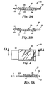
- the first laminate 12 is similarly provided on bottom surface 66 of spacer 62 with exposed surface 22 of porous matrix 20 adjacent the bottom surface 66. As illustrated in Figure 3A, spacer 62 maintains the viscoelastic material 38 and porous matrix 20 out of contact with one another when the indicator is in its unactivated state.
- the first laminate 12 must at least partially overlay the opening 68 and a portion of the second laminate 30 such that a portion of the first laminate 12 and second laminate 30 may be brought into contact with one another through opening 68 when the indicator is in its activated state as illustrated at A in Figure 3B.
- the first laminate 12 may be mounted to the bottom surface 66 of spacer 62 by means of a pressure sensitive adhesive around the periphery of the bottom surface 68 of the spacer 62.
- the first laminate 12 may be mechanically mounted on the spacer 62 by means of staples or any suitable blister pack or other housing or case.
- the spacer 62 can maintain the viscoelastic material 38 out of contact with the porous matrix 20 for a prolonged period of time to keep the indicator in its unactivated state.
- This provides the advantage of having an indicator 60 with a very long shelf life prior to activation. This allows the indicator 60 to be fabricated at a place and time remote from the object to which it will ultimately be adhered.
- the indicator 60 may be mounted on an empty container, such as a food can or jar, or a medicine vial, for example, and remain unactivated for a long period of time. After the container is filled with its desired contents, the indicator 60 may then be activated as illustrated in Figure 38. This may be done simply with a finger, or by use of a suitably sized plunger, brush, or other device.
- the indicator may also be maintained in its unactivated state after the container is filled and may, for example, be activated when the container is first opened, for example by the gripping force of a user's hand while removing a cap from a container.
- the actuating means of this embodiment comprises a barrier film 63.
- the barrier film 63 may comprise, for example, any suitable paper or film release liner or sheet.
- Barrier film 63 is disposed between at least a portion of second laminate 30 and first laminate 12.
- the exposed surface 40 of the viscoelastic material 38 is adjacent one side of the barrier film 63, while exposed surface 22 of porous matrix 20 is adjacent the other side of the barrier film.
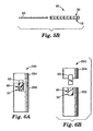
- First laminate 12 and second laminate 30 may be adhered to one another along three edges of their peripheries around the barrier film 63. To activate the indicator, barrier film 63 is pulled in direction B as shown in Figure 5A.
- first laminate 12 and second laminate 30 may come into contact with one another as illustrated in Figure 5B. It is also possible to sequentially activate portions of the indicator by partially removing barrier film 63.
- the barrier film 63 is preferably J-folded as shown to facilitate removal by having a sliding release against the porous matrix 20 and a peel off, non-sliding release from the exposed surface 40 of the viscoelastic material 38.
- the first laminate 12 and second laminate 30 may be connected at only one edge, with an unfolded barrier film 63 being removed by folding open the first and second laminates far enough to allow the barrier film 63 to be peeled off of the second laminate 30.
- Barrier film 63 may be advantageously employed when it is desired to delay activation of the indicator.
- the indicator can be fabricated at a time and place remote from the object whose cumulative thermal exposure is to be monitored.
- the indicator can be activated when attached to the object by removing the barrier film.
- the activator can be mounted on an empty container and activated upon filling the container as described with reference to the embodiment of Figure 2.
- the present embodiment may be used where it is desired to activate the indicator after a user opens the container and thereby exposes the contents to ambient conditions or adds or mixes ingredients.
- an indicator according to the present embodiment may be affixed to a container 250 which is sold to the end user with the indicator unactivated.
- the indicator may be affixed to the body 252 of the container while the exposed end of the barrier film may be connected to the cap 254 of the container as illustrated in Figure 6A. Removal of the cap 252 would withdraw the barrier film 63 from the indicator as illustrated in Figure 6B, thereby activating the indicator.
- Such an arrangement may be advantageously employed with cosmetics, for example.
- barrier film 63 acts as an elongate, continuous carrier for a plurality of unactivated indicators 10.
- each discrete indicator 10 includes first laminate 12 and second laminate 30 adhered to one another along a single edge.
- This embodiment provides convenient means for storing in roll form a plurality of indicators 10.
- Also illustrated in this embodiment is an elongate, continuous embodiment of release liner 28.
- Such an optional embodiment of the release liner can serve as a carrier for the discrete indicators 10 after the barrier film 63 has been removed to activate the indicators. Individual indicators can then be peeled from the continuous release liner 28 and applied to a desired object.
- first and second laminates 12 and 30 are elongate and continuous, as is barrier film 63.
- first and second laminates 12 and 30 are joined at one edge.
- the barrier film 63 maintains the indicator 10 in its unactivated state by keeping the first and second laminates 12 and 30 out of contact from one another. In this manner, a roll form of the unactivated indicators 10 can be conveniently shipped and stored for long periods of time.
- This embodiment is activated by continuously feeding the first and second laminates 12 and 30 in direction A while removing the barrier film 63 in direction B.
- the barrier film may be folded upon itself to allow a sliding removal relative to the porous matrix and a peeling removal relative to the viscoelastic material without the necessity for a J-fold in the barrier film 63.
- the elongate, activated indicator 10 may be cut or otherwise separated into discrete indicators for application to desired objects.
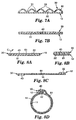
- the second laminate 30 comprises a first backing 32 which is embossed to have valleys, or proximate portions, 31, and peaks, or remote portions, 33.
- the valleys 31 are initially adhered to the corresponding portions of the porous matrix 20, and may or may not locally transparentize those portions.
- the first and second laminates are maintained substantially out of contact in the raised areas, or peaks 33.
- the indicator is activated by pressing on the second laminate 30 with any suitable means to cause at least a portion of the peaks 33 to come into contact with the porous matrix 20.
- the viscoelastic material 38 is a pressure sensitive adhesive, this will maintain the peaks in contact with the porous matrix.
- Other suitable mechanical means may be provided for maintaining contact, such a blister pack which, when depressed, will maintain pressure on the second laminate 30.
- the substrate 14 of first laminate 12 may similarly have formed therein proximate portions and remote portions in addition to or instead of the second laminate 30.
- FIG. 8A and 8B Another preferred embodiment of the actuating means is illustrated in Figures 8A and 8B.
- This embodiment includes actuating substrate 61 which can comprise any suitable construction including those described herein for substrate 14 and backing 32.
- First laminate 12 and second laminate 30 are each affixed to actuating substrate 61 alongside one another by any suitable means, such as a pressure sensitive adhesive.
- the exposed surface 22 of porous matrix 20 and the exposed surface 40 of viscoelastic material 38 both face away from activating substrate 61, maintaining the indicator in its unactivated state as illustrated in Figure 8A.
- a release liner 65 is initially affixed to the exposed surfaces 22 and 40 to prevent contamination.
- first laminate 12 and second laminate 30 can be affixed to opposite surfaces of substrate 61 as illustrated in Figure 8C, to be wrapped around an object or container 11, and brought into overlapping contact as illustrated in Figure 8D.
- a mounting adhesive 26 may be included on the substrate 61 as shown.
- the actuating means comprises spacing bodies 67 disposed between the first laminate 12 and second laminate 30.
- Spacing bodies 67 are illustrated as spherical, but may be of any suitable configuration, including polyhedrons such as cubes, or bars, rods, ribs, wires and the like. Spacing bodies 67 are sized and arranged to keep the exposed surface 40 of the viscoelastic material 38 and the exposed surface 22 of the porous matrix 20 substantially out of contact when the indicator is in its unactivated state as illustrated in Figure 9A.
- the indicator is activated by pressing on the indicator with any suitable means to bring the exposed surfaces 40 and 22 in substantial contact with one another between the spacing bodies 67 as illustrated in Figure 9B.
- viscoelastic material 38 conforms around the spacing bodies 67 when using spacing bodies which retain their shape.
- the spacing bodies may collapse under pressure, as is taught in U.S. Patent No. 3,413,168, "Adhesive Bonding Method Permitting Precise Positioning,” (Danielson et al.).
- actuating means 200 includes a base 212 having integral upstanding arcuate walls defining shoulders 214 which in turn define an interior cavity 216.
- the shoulders 214 are separated by diametrically opposed locating slots 218.
- the base 212 and the integral upstanding shoulders 214 may be constructed of any material having suitable rigidity, and are preferably formed of polyester film.
- First laminate 12 is sized to be accepted within the reservoir 216 adjacent the base 212, with exposed surface 22 facing away from base 12.
- First laminate 12 includes diametrically extending tabs 21 which are adapted to fit within the base slots 218 and which extend beyond the outer surface of the shoulders 214. The tabs 21, in conjunction with the slots 218, prevent rotation of the first laminate 12 and are utilized to maintain the first laminate 12 adjacent the base 212 in a manner to be described hereinafter.
- Second laminate 30 is sized to rest upon the shoulders 214 and not extend beyond the outer surfaces of the upstanding shoulders 214. Exposed surface 40 faces first laminate 12.
- a cover 226 overlies the second laminate 30, first laminate 12, and the base 212 and includes a cylindrical wall 228 adapted to fit closely around the outer surface of the shoulders 214, an inwardly extending ledge 230 formed as an annular ring overlying the shoulders 214, a convergently sloped central portion 232 attached at its periphery to the ledge 230 and a perimetrical boundary 234 coextensive with the base 212.
- the boundary 234 may be attached to, or sealed to if preferable, the base 212 by any suitable means such as adhesive bonding, heat sealing, spot welding, or the like.
- the inwardly extending ledge 230 bears against the upstanding shoulders 214 and clamps the second laminate 30 therebetween.
- second laminate 30 may be adhered to the inner surface of dome 232.
- viscoelastic material 38 may be applied directly to the inner surface of dome 232, in which case dome 232 takes the place of first backing 32.
- the tabs 21 extend through the slots 218 and beyond the outer surface of the shoulders 214, the tabs 21 are contained between the boundary 234 and the base 212, simultaneously preventing rotation and upward movement of the tabs 21 and the first laminate 12. It will be recognized that the tabs 21 may be eliminated and upward movement of the first laminate 12 prevented by fastening the first laminate 12 to the base 212 by such conventional means as adhesive bonding or mechanical fasteners.
- the convergently sloped portion 232 Central to the cover 226 is the convergently sloped portion 232 which may assume any pyramidal or conical shape which will permit inversion, but for simplicity of manufacture is preferably formed as a shallowly curved convex spherical dome attached at its periphery to the ledge 230.
- the dome 232 had a radius selected to permit a "snap" movement between non-activated and activated positions of stability and opposite curvature, as shown in Figures. 11A and 11B, respectively.
- the cover 226 may be formed of any material suitable for the base 212, with the additional constraint that the domed portion 232 must be transparent to afford visual observation into the actuating means 200.
- Figure 11A shows the dome 232 in its unactivated position; extending convexly away from the base 212.
- the dome 232 Upon application of force to the outer surface of the dome 232, the dome 232 travels a short distance and then snaps to its second position of stability, the activated position, which is exteriorly concave to press against the base 212 within the cavity 216, as shown in Figure 11B.
- the activated position When in the activated position, the dome 232 maintains the second laminate 30 contact with the first laminate 12.
- the outer surface of the base 212 may be coated with a pressure sensitive adhesive 226 and covered with an overlying protective film or release liner 228.
- a small hole 240 communicating between the outer surface of the cover 226 and the inner reservoir 216 is provided in the ledge 230 to permit the escape of air trapped within the actuating means 200 as the dome 232 moves from its non-activated position to its activated position.
- any of the indicators described herein may be provided with more than one second laminate 12. As seen in Figure 12, it is possible to have, for example, three second laminates 72, 74 and 76. Each of the second laminates can have a different viscoelastic material 38 to indicate a respective predetermined allowable cumulative thermal exposure.
- the indicator may also, or instead, have a plurality of different porous matrices 20 to provide varying migration rates or runout times for the indicator.
- the plurality of porous matrices 20 may also have different substrate colors and/or densities to provide a variety of desired visual indications. It is possible to have separate substrates 14 each having a different porous matrix 20, or a plurality of porous matrices 20 formed on a single substrate 14.
- the indicator of the present invention can comprise latent indicia 50 which initially is not visually observable when the porous matrix 20 is opaque prior to migration of the viscoelastic material 38 into the matrix.
- the latent indicia 50 becomes visually observable as migration of the viscoelastic material 38 into the porous matrix 20 renders the matrix 20 increasingly light transmissive.
- the indicator can include obscurable indicia 51 instead of latent indicia ( Figures 14A, 14B, and 14C) or in addition to latent indicia ( Figures 15A and 15B).
- the obscurable indicia 51 is initially visually observable when the porous matrix 20 is opaque prior to migration of the viscoelastic material 38 into the matrix 20.
- the obscurable indicia becomes increasingly obscured as migration of the viscoelastic material 38 into the porous matrix 20 renders the matrix 20 increasingly light transmissive.
- the indicator can thereby provide a visually observable indication of cumulative thermal exposure by revealing latent indicia 50, obscuring obscurable indicia 51, or both.
- the visually observable indication is provided when a latent indicia is sufficiently revealed to be visually observable or readable with a bar code scanner or other such device, or when an obscurable indicia is sufficiently obscured such that its change in appearance is visually observable or the obscurable indicia is no longer readable by a user or with a bar code laser scanner or other such optical comparison device. It is not necessary to completely obliterate an obscurable indicia, although the indicator may do so when the porous matrix 20 becomes light transmissive.
- the latent indicia 50 may be provided in any of several ways.
- the optical density of the latent indicia 50 preferably increases by at least 0.2 as the viscoelastic material 38 migrates into the porous matrix 20.
- An indicator may include one or more latent images provided in any combination of the manners described herein. If the substrate 14 is light transmissive, it is possible to provide latent indicia on the first side 16 of substrate 14. As the matrix 20 becomes transparent, the latent indicia 50 becomes visually observable through the substrate 14, matrix 20, viscoelastic layer 38, and backing 32 Similarly, the latent indicia 50 can be provided on an optional second substrate provided on the first side 16 of substrate 14. The latent indicia 50 may be provided on the object 11 itself when the indicator is mounted on the object 11 as seen in Figure 1B.
- the latent indicia 50 may be provided on the second side 18 of the substrate 14, with the porous matrix 20 overlaying the latent indicia.
- the substrate 14 it is not necessary that the substrate 14 be light transmissive, although it may be light transmissive.
- the substrate 14 is opaque to provide a contrasting background for latent indicia 50 provided on second side 18 of the substrate.
- the porous matrix 20 becomes light transmissive, the latent indicia becomes visually observable through the matrix 20, viscoelastic layer 38, and backing 32.
- Latent indicia 50 may be provided in or on the exposed surface 40 of the porous matrix 20, as illustrated in Figure 13A.
- an invisible repellent 52 is applied to a first portion 54 of the porous matrix 20 as is taught in U.S. Patent No. 5,354,598, "Article Capable of Displaying Defined Images,” (Arens).
- the viscoelastic material 38 can migrate into the second portion 56 of the porous matrix at 20b in response to thermal exposure, but cannot migrate into the first portion 54 of the porous matrix at 20a as illustrated in Figure 13C.
- the repellent may slow the migration rather than prevent it, and thereby provide a two step indication of thermal exposure
- the latent indicia 50 becomes visually observable as the second side 18 of the substrate becomes visually observable through the second portion 56 of the matrix, as illustrated in Figure 13B.
- the second portion 56 of the porous matrix may provide a negative image of the latent indicia as illustrated in Figure 13B, or may instead provide a positive image of the latent indicia.
- the repellent may be applied to the exposed surface 40 of the viscoelastic material.
- the repellent 52 will then slow or prevent migration locally as described above.
- the repellent 52 may be any suitable material to locally slow or prevent migration of the viscoelastic material 38 into the first portion 54 of the porous matrix.
- One preferred repellent comprises a fluorochemical repellent available under the tradename ScotchgardTM, available from Minnesota Mining and Manufacturing Company, St. Paul, Minnesota.
- Other suitable repellents include Elmers Glue-AllTM, available from Borden Inc., Cincinnati, Ohio, and silicone.
- Latent indicia may be similarly provided by applying viscoelastic material 38 to backing 32 in a pattern comprising the latent indicia.
- the latent indicia may be provided by reverse printing a latent textual message such as "REPLACE” with the viscoelastic material 38 on the backing 32.
- This pattern coating will migrate into the porous matrix 20 to locally increase the light transmissivity of the porous matrix.
- the latent indicia 50 becomes visually observable.
- the porous matrix 20 can be applied in a pattern to substrate 14.
- the obscurable indicia 51 may be provided in any of several ways.
- An indicator may include one or more obscurable images provided in any combination of the manners described herein. What is common to the embodiments of obscurable indicia described below is that the obscurable indicia becomes less discernible against its background as the viscoelastic material 38 migrates into the porous matrix 20 and renders the matrix increasingly light transmissive. For example, as the second side 18 of the substrate 14 becomes increasingly visible through the porous matrix 20, the obscurable indicia 51 becomes less discernible.
- the color and optical density of the second side 18 of the substrate and of the obscurable indicia 51 are chosen such that the contrast of the obscurable indicia 51 against its background is reduced as the light transmissivity of the porous matrix 20 increases. If a light transmissive substrate 14 is used, the increasing visibility of an optional second substrate or of the object 11 renders the obscurable indicia 51 less discernible.
- the difference of the optical density of the obscurable indicia 51 relative to its background decreases by at least 0.2 as the viscoelastic material 38 migrates into the porous matrix 20.
- the obscurable indicia 51 may be provided on the porous matrix 20.
- the obscurable indicia may be printed on the exposed surface 22, and should have a color and density similar to the second side 18 of the substrate. As the porous matrix 20 becomes increasingly light transmissive, the contrast of the obscurable indicia 51 against the second surface 18 is sufficiently decreased to obscure the indicia.
- the obscurable indicia 51 may be provided by permanently transparentizing a portion of the porous matrix 20, as is known in the art and is exemplified by U.S. Patent No. 4,428,321, "Thermally-Activated Time-Temperature Indicator.” As the viscoelastic material 38 migrates into the remainder of porous matrix 20, the matrix becomes increasingly light transmissive to thereby make the second side 18 of the substrate 14 increasingly visible. This will reduce the contrast between the obscurable indicia 51 and the permanently transparentized portion of the matrix 20 to thereby obscure the indicia. In either of the above two embodiments, the obscurable indicia 51 is initially visually observable through the viscoelastic material 38, first backing 32, and optional second backing 42, if present.
- the obscurable indicia 51 may be printed on the exposed surface 40 of the viscoelastic material 38. It will initially be visually observable through the viscoelastic material 38, first backing 32, and optional second backing 42, if present.
- the obscurable indicia may be provided on the first surface 34 or the second surface 36 of the backing 32.
- the obscurable indicia may be present on optional light transmissive backing 42 which may be provided on second surface 36 of first backing 32 as seen in Figure 1A.
- the obscurable indicia comprises a bar code 51 which is initially observable as seen in Figure 14A.
- the porous matrix 20 becomes increasingly light transmissive, the second side 18 of substrate 14 becomes visible, reducing the contrast between the bar code 51 and its background sufficiently to render the bar code unreadable by a bar code reader as illustrated in Figure 14B.
- Figure 14B For clarity, only a portion of the bar code is illustrated as obscured in Figure 14B, although generally all of the porous matrix will obscure the bar code at approximately the same rate after the indicator is activated.
- the obscurable indicia 51 can be obscured by latent indicia 50 which can comprise lines or bands which appear across the obscurable indicia 51 as illustrated in Figure 14C.
- the latent indicia can be provided by pattern coating the viscoelastic material 38 on backing 32 as described above.
- the indicator may comprise both latent indicia 50 and obscurable indicia 51.
- the obscurable indicia 51 is initially visually observable as seen in Figure 15A. As the second side 18 of substrate 14 becomes visible, the contrast of obscurable indicia 51 is reduced until it is no longer discernible, as seen in Figure 15B.
- the latent indicia 50 initially is not visually observable as illustrated in Figure 15A, and becomes visually observable as a positive image as illustrated in Figure 15B.
- the indicator may provide a visually observable indication of cumulative thermal exposure by means of a simple latent image 50 which can be, for example, a circular or rectangular patch.
- a comparison image 58 which can be provided anywhere on the indicator, preferably immediately adjacent to the latent image 50.
- the comparison image 58 can be printed on the top surface 64 of spacer 62 immediately adjacent opening 68 as illustrated.
- the comparison image can be provided in any of the manners described above for providing an obscurable image.
- the comparison image 58 may be provided on the porous matrix adjacent the latent image by printing on a portion of the porous matrix 20 or by permanently transparentizing a portion of the porous matrix as described above.
- comparison image 58 may be printed on the first backing 32 or second backing 42. As described above, migration of the viscoelastic material 38 into the porous matrix 20 will render the latent image 50 increasingly visually observable. When the latent image 50 matches the comparison image 58 in color and density, this provides the visually observable indication of cumulative thermal exposure.
- the comparison image 58 may comprise a plurality of colors and/or densities.
- the comparison image 58 may comprise three areas of increasing density as illustrated in Figure 16A. A visually observable indication of predetermined thermal exposure is provided when the latent image 50 is darker than the lightest comparison image, matches the intermediate comparison image, and is lighter than the darkest comparison image as illustrated in Figure 16B.
- Figure 24 is a plan view of first laminate 12 comprising a circular planar substrate 14 with porous matrix 20 thereon. The circular substrate and porous matrix are adhered to a continuous, elongate backing 15 having adhesive 26 and release liner 28 thereon.
- Figure 25 is a plan view of the second laminate 30 comprising an oval light transmissive backing 32 with viscoelastic material 38 thereon.
- Comparison image 58 is in this embodiment an image printed on the exposed surface 40 of the viscoelastic material, with an unprinted area 58 in the center of the image.
- the light transmissive backing 32 is adhered to continuous, elongate second light transmissive backing 42.
- the first and second laminates can be stored apart in roll form for long periods of time.
- This indicators are then activated by adhering together the first and second laminates 12 and 30, which must be indexed such that the viscoelastic material 38 overlays the porous matrix 20.
- a cross-sectional view of the activated indicator is illustrated in Figure 26 in which the thicknesses of the elements have been expanded for illustrative purposes. After adhering together the elongate first and second laminates 12 and 30, individual indicators 10 can be cut and then adhered to a desired object.
- the elongate, continuous first and second laminates can be stored together with a barrier liner therebetween (not illustrated) as described above with respect to the embodiments illustrated in Figures 20-21 and 22-23.
- individual indicators 10 can be constructed according to this embodiment by adhering together discrete segments of the first and second laminates 12 and 30 just described.
- the latent indicia 50 and obscurable indicia 51 may comprise any suitable indicia, including but not limited to textual messages, graphical images, and UPC bar codes.
- the indicia can be, for example, a printed message to be read by the user.
- a latent image such as "EXPIRED,” “DO NOT USE,” or the like may be used to indicate cumulative thermal exposure exceeding a predetermined allowable maximum.
- An obscurable image such as “FRESH” may be used in addition to, or in place of, the latent image. The indication "FRESH” would become obscured to indicate cumulative thermal exposure exceeding a predetermined allowable maximum.
- a latent and obscurable image may be combined such that a portion of an image is obscured or replaced by a latent image.
- obscurable and latent indicia can be combined such that as the latent indicia becomes visible it reduces the contrast of the obscurable indicia until they are substantially the same such that neither the latent nor obscurable indicia is individually discernible. With continued migration of viscoelastic material, the latent indicia can become darker than the obscurable indicia, thereby reversing the obscurable indicia from a positive to negative image, or from a negative image to a positive image.
- the indicia may comprise a laser readable bar code such as a UPC symbol.
- An obscurable bar code indicia would be obscured to indicate cumulative thermal exposure exceeding a predetermined allowable maximum. With the bar code obscured, it would not be readable by a laser bar code reader, thereby preventing sale of an object whose useful shelf life is exceeded.
- a latent bar code indicia could be used in combination with an obscurable bar code indicia to reprice an item as the remaining shelf life is reduced.
- One useful method for measuring the effectiveness of the indicator in providing latent bar code indicia or obscuring an obscurable bar code indicia 51 is by use of an optical meter which provides measurements of the Hunter L scale.
- the Hunter L scale is a measure of the blackness of an object.
- This progression can be measured on the Hunter L scale, and has been observed to decrease from a value of about 70 prior to migration of the viscoelastic material 38 to a value of about 20 when the viscoelastic material 38 substantially fills the voids of the matrix 20.
- An obscurable bar code indicia 51 is printed on the exposed surface 22 prior to activation of the indicator. When the indicator undergoes cumulative thermal exposure, Hunter L measurements are taken. Also, the obscurable bar code indicia is scanned with a laser scanner of the type known as the Quick-Check 5 with a 633 wand, available from Photographic Sciences Corp., of Webster, New York. It has been observed that as the Hunter L value of the activated matrix 20 passes below approximately 58-60, the contrast between the obscurable bar code indicia 51 and its background is sufficiently reduced that the bar code reader can no longer read the obscurable bar code 51.
- any of the indicia described herein may be printed on the various components of the indicator by means of any known printing technique including, but not limited to, offset printing, screen printing, thermal transfer, electrophotography, flexographic printing, or rotogravure printing.
- the indicator of the particular embodiments described herein was described as having a transparent second laminate 30 through which the visually observable indication could be viewed, and was described as being mountable on object 11 such that first laminate 12 was adjacent the object. It will be recognized of course, that the present invention is not so limited, and instead can include transparent substrate 14 to allow viewing the visually observable indication through the first laminate 12. In such a construction, the indicator could be mounted to object 11 such that viscoelastic material 38 is proximate the object 11. Such an arrangement may include mounting the viscoelastic material directly on the object 11, in which case the object 11 would act as backing 32, and a separate backing 32 may be omitted.
- the indicator can provide a visually observable indication by selecting a viscoelastic material and porous matrix having sufficiently different indices of refraction such that migration of the viscoelastic material decreases the light transmissivity of the porous matrix.
- a tint may be added to the backing, the viscoelastic material, the porous matrix, and/or the substrate of any of the embodiments described herein as desired to produce the desired visually observable indication.
- the indicator of the present invention can be used with a wide variety of objects 11 in addition to the illustrative, non-limiting applications discussed above.
- the indicator can be used to indicate the time at which an object should be discarded, replaced, or serviced, even if the object does not degrade in response to temperature or is normally used at room temperature.
- the indicator can be applied to a toothbrush to provide an indication of when the toothbrush should be discarded.
- the indicator of the present invention can also be advantageously used as a type of security badge or pass.
- the indicator could be fabricated to indicate a predetermined allowable time at room temperature, for instance. Such an indicator could be incorporated in a badge or pass to allow someone access to an area for a desired period of time, such as a day or any desired number of days.
- the indicator would be activated at the start of the allowable period and would provide a visually observable change to indicate the allowable period had lapsed.
- the present invention also includes the following methods of providing a time-temperature integrating indicator.
- the embodiment described with reference to Figures 1A and 1B may be advantageously constructed by means of apparatus 80 schematically illustrated in Figure 17.
- Apparatus 80 includes unwind roll 82 on which is wound a length of second laminate 30.
- Apparatus 80 further includes unwind roll 84 on which is wound a length of first laminate 12.
- the first laminate is unwound from unwind roll 84 and passes by print station 86.
- Print station 86 applies a latent or obscurable indicia as described above.
- the strip of first laminate 12 may already comprise indicia before it is wound on unwind roll 84.
- Second laminate 30 is simultaneously, or sequentially, unwound from unwind roll 82.
- Second laminate 30 may optionally pass by a print station similar to 86, or may itself already comprise indicia before it is wound on unwind roll 82.
- First laminate 12 and second laminate 30 are brought into contact at the nip formed between idler rolls 90 and 92 such that exposed surface 22 of the porous matrix 20 is brought into contact with exposed surface 40 of the viscoelastic material 38, thereby activating the indicator.
- Cutter 94 cuts the long indicator into discrete indicators which are then applied to objects 11 or to a continuous liner for subsequent application to objects 11.
- the first laminate may be initially adhered to the object 11 and second laminate 30 may subsequently be mounted onto first laminate 12.
- the indicator is unactivated prior to bringing the first and second laminates into contact.
- Apparatus 80 is one embodiment of an actuating means according to the present invention.
- Apparatus 100 is particularly suited for providing indicators fabricated in accordance with the embodiment described with respect to Figure 2.
- Apparatus 100 comprises unwind roll 102 on which is wound a length of second laminate 30, unwind roll 106 on which is wound a length of first laminate 12, and unwind roll 104 on which is wound a length of material for forming spacer 62.
- the spacer material is unwound from unwind roll 104 and progresses to punch 108 and back up 110 for forming opening 68 in the spacer 62. Cut outs 69 are ejected from the spacer material.
- the spacer material continues past an adhesive coater 111 and on to the nip formed between idler rolls 112 and 114.
- First laminate 12 and second laminate 30 are unwound from their respective rolls and progress to the nip formed between rolls 112 and 114, either simultaneously or sequentially.
- Second laminate 30 is adhered to top surface 64 of the spacer 62 such that exposed surface 40 of the viscoelastic material 38 adheres to the top surface 64 and covers opening 68.
- First laminate 12 is adhered to the bottom surface 66 of the spacer 62 such that exposed surface 22 of porous matrix 20 adheres to bottom surface 66 and also covers opening 68.
- the indicator remains in its unactivated state with the viscoelastic material 38 and matrix 20 maintained out of contact as illustrated in Figure 3A.
- the indicator then passes to cutter 116 where it is cut into discrete indicators 60 as shown.
- the indicator can be cut into lengths of several adjoining indicators with perforations therebetween to be separated later as illustrated in Figure 19.
- the indicators may be stored unactivated for a long period of time until they are affixed to an object to be monitored and then activated.
- the runout time is the time required for an indicator, after it has been activated, to turn from a Color 'L' value of about 65 to a Color 'L' value of 30 in response to cumulative thermal exposure
- the Color 'L' is the HunterLab measure of how light or dark a sample is Higher numbers, i.e., closer to 100, indicate progressively lighter shades of gray approaching white, while numbers approaching 0 indicate progressively darker shades of gray approaching black. Intermediate numbers, between about 25 and 75 are visually distinguishable shades of gray
- the color of a time-temperature indicator is measured before activating, and monitored on a periodic basis after activating, using a spectrophotometer (X-RiteTM SP 68 Spectrophotometer available from X-Rite Inc., Grandville, MI).
- the readings are recorded and analyzed using QA-MasterTM software (available from X-Rite, Inc.), and the HunterLab Color 'L' value is selected as the measuring system. The test is performed according to manufacturer's instructions and calibrated with the standard color tiles.
- T g glass transition temperature of the viscoelastic material, in degrees Centigrade, is determined using a differential scanning calorimeter (DSC 2920 available from TA Instruments Inc., New Castle DE) and thermal analyzer software (TA 2200 Thermal Analyzer from TA Instruments), or using a DSC 2200 and related software (formerly available from DuPont Co.)
- the effective activation energy (Ea) of the viscoelastic material in kilocalories per mole (Kcal/mole) is determined using the Arrhenius relationship discussed above.
- the rate constant, k is determined at several temperatures, T, for each viscoelastic material, typically at 12°C, 22.4°C, 30°C, 40°C, and 50°C.
- T temperature
- a plot is then drawn of In(k) vs. 1/T(°Kelvin).
- a best fit straight line is then determined for the data, the slope of which represents the value of the effective Ea/R, where R is the universal gas constant, 1.987 cal/mole°K.
- the slope of the line is then multiplied by R to calculate Ea which is reported in the results tabulated below.
- the inherent viscosity of the viscoelastic material is determined using a Canon-Fenske #50 viscometer in a water bath controlled to 25-27 C. The viscosity is measured in ethyl acetate at the concentration indicated in grams per deciliter (g/dl). The procedure is described in ASTM D2857-93. The inherent viscosity provides an indication of molecular weight of the viscoelastic material
- a dispersion was prepared by mixing 23.23 parts toluene, 3.24 parts disisobutyl ketone, 6.5 parts methyl isobutyl ketone, 7.49 parts hydroxy functional acrylic resin (G-Cure 868-RX-60 available from Henkel Co .), 57.01 parts sodium potassium aluminum silicate (MinexTM10 available from Indusmin Limited), 1.11 parts cellulose acetate butyrate (CAB 500-5 available from Eastman Chemical Co.), and 1.42 parts hexamethylene diisocyanate (DesmodurTMN-75 available from Mobay Chemical Co.).
- a laminate having a porous matrix on one side was prepared by curtain coating the dispersion onto a 0.2 mm thick paper laminate construction having two sheets of 40-pound black machine glaze kraft paper that are laminated together by extruding high density polyethylene between the sheets and calendering to a thickness of about 0.18 millimeter (basis weight of the laminate was about 65 grams/square meter).
- the coating was dried in a forced air oven for about one minute at 100 C to provide a dry coating thickness of about 12.7 micrometers (0.5 mils).
- a dispersion was prepared by mixing 16.52 parts toluene, 8.23 parts hydroxy functional acrylic resin (G-Cure 868-RX-60), 73.5 parts calcium carbonate (Dryca Flo 125 available from Sylacauga Calcium Products), and 1.42 parts hexamethylene diisocyanate (DesmodurTMN-75).
- a laminate having a porous matrix on one side was prepared by curtain coating the dispersion onto a 0.2- mm thick paper laminate construction having two sheets of 40-pound rose colored machine glaze kraft paper that are laminated together with high density polyethylene as in Substrate 1.
- the coating was dried in a forced air oven for about one minute at 100 C to provide a dry coating thickness of about 12.7 micrometers (0.5 mils).
- a laminate was prepared as in First Laminate B using a green colored kraft paper.
- a laminate was prepared as in First Laminate B using a blue colored paper.
- An acrylate viscoelastic composition was prepared by mixing 100 parts of isooctylacrylate with 0.002 part 2,2'-azobis(isobutyronitrile) initiator (VazoTM64 available from DuPont Company) in 81.8 parts of a solvent mixture having 98 parts ethyl acetate and 2 parts isopropanol in a quart jar. The jar was purged with nitrogen for 2 minutes at 1 liter per minute, sealed, and placed in a rotating heated water bath for 24 hours at about 55°C. The percent solids was 55%, and the inherent viscosity, as determined according to the above-described procedure at a solids concentration of 0.25 grams/deciliter, is shown in Table 1.
- a second laminate was prepared by coating the above composition to a dry coating weight (Coat Weight) of 0.38 gram per 155 square centimeters (g/155 cm 2 ) onto a 0.05 millimeter thick optically transparent corona treated polyester film which had been treated on the reverse side with a release coating (carbamate copolymer of polyvinylalcohol and octadecyl isocyanate as disclosed in U.S. Patent No. 2,532,011 (Dahlquist, et al).
- the second laminate was dried in an oven at about 71°C for about 7 minutes.
- a time temperature indicator was prepared and activated by applying a 2.54 cm wide strip of the second laminate to First Laminate A and then immediately rolling down with a 2.3 kilogram (5 pound) roller.
- the Color 'L' value was determined to be about 65.
- the Color 'L' value was measured on a periodic basis (hourly, daily, weekly, etc., as appropriate for how quickly the indicator changed in darkness) until the Color 'L' value dropped to 30. Test results are shown in Table 1.
- Time temperature indicators were prepared as in Example 1 except that the ethyl acetate/isopropanol ratios were varied as shown in Table 1. Different inherent viscosities were obtained by changing the solvent blend ratio of ethyl acetate/ isopropanol as indicated in the table: Ex Solvent Blend Inherent Viscosity Coat Weight g/155 cm 2 Ea Kcal/mole Runout Time - Days at 22.4C 1 98/2 0.92 0.38 13.6 15 2 96/4 0.69 0.36 12.2 3 3 94/6 0.56 0.37 13.5 1.3 4 92/8 0.48 0.38 13.6 0.8
- Time temperature indicators were prepared as described in Example 1 except that the percent solids were varied as shown in Table 2.
- the solvent was ethyl acetate.
- Polymerization conditions for Examples 5-7 were the same as in Example 1.
- Example 8 had 0.15 part VazoTM64 initiator and the polymerization was carried out at 50°C. All of the samples were purged with nitrogen for 3 minutes at 1 liter per minute before polymerizing. Results are shown in Table 2.
- Ex % Solids Inherent Viscosity Coat Weight g/155 cm 2 Ea kcal/mole Runout Time - Days 22.4°C 50°C 5 45 1.31 0.53 16.6 143 14 6 50 1.44 0.41 15.4 >165 40 7 55 1.57 0.40 13.6 >165 72 8 55 2.03 0.36 13.8 >165 180
- Time temperature indicators were prepared similarly to Example 1 except using a viscoelastic composition having 94 parts isooctyl acrylate (IOA) with 6 parts acrylic acid (AA) with 002 parts VazoTM 64 initiator.
- the viscoelastic material has an inherent viscosity of 0 80 measured at a concentration of 0.25 grams/deciliter.
- Viscoelastic compositions for Examples 10-23 were prepared by adding tackifiers and/or plasticizers to the viscoelastic composition in the amounts shown in Table 3 per 100 parts of the acrylate viscoelastic material (phr).
- Examples 10-14 had varying amounts of a rosin ester tackifier (ForalTM 85 available from Hercules, Inc., of Wilmington, Delaware)
- Example 15 included dioctyl phthalate, a plasticizer.
- Ex Tack phr Plas phr Tg C Ea kcal/mol Coat Weight g/155 cm 2 Runout Time Temp C Days 9 0 0 -42.1 16.8 0.37 20.5 >481 10 25 0 -29.3 22.8 0.37 20.5 >550 11 50 0 -23.2 24 0.44 20.5 >481 12 55.6 0 -21.3 23.7 0.40 20.5 >481 13 75 0 -15.7 23.9 0.46 22.4 >369 14 100 0 -9.2 25.6 0.51 22.4 >369 15 0 10 -- 17.3 0.51 2
- the data in Table 3 show how varying amounts of plasticizers and/or tackifiers can be added to a viscoelastic material to modify the glass transition temperature, the activation energy, and the runout time of an indicator.
- Time temperature indicators were prepared as in Example 1 except that Example 24 used a viscoelastic material which had a composition, by weight, of 50 parts ethyl acrylate and 50 parts methyl acrylate, and Example 25 used a viscoelastic material which had a composition, by weight, of 18 parts ethyl acrylate and 82 parts methyl acrylate.
- the solvent used for these examples was a 90/10 mixture of ethyl acetate/isopropanol. Test results are shown in Table 4.
- Time temperature indicators were prepared as in Example I except that Example 26 used a viscoelastic material which had a composition of 60 parts isooctyl acrylate and 40 parts isobornyl acrylate, and Example 27 used a viscoelastic material which had a composition of 53 parts isooctyl acrylate and 47 parts isobornyl acrylate.
- the solvent used for these examples was a 99/1 blend of ethyl acetate/isopropanol. Test results are shown in Table 4.
- a pressure sensitive adhesive composition was prepared by compounding 100 parts of a styrene-isoprene-styrene block copolymer (KratonTM 1107 available form Shell Chemical Co.), 100 parts hydrocarbon tackifying resin (WingtackTM Extra available from The Goodyear Company) and 100 parts of tackifying resin (ZonarezTM A25 available from Arizona Chemical Co.) in 400 parts of toluene. Also added were antioxidants (1.5 parts IrganoxTM 1076 available from Ciba Geigy, and 1.5 parts CyanoxTM LTDP available from American Cyanamid Co.).
- the adhesive composition was coated to a dry coating thickness of 30.5 micrometers onto a transparent corona treated biaxially oriented polypropylene film to form a second laminate.
- a time temperature indicator was then prepared by laminating a 2.54 cm wide strip of the second laminate with a 2.3 kg roller to samples of the first laminate which had been printed with black UPC bar codes. The indicators were then measured for Color 'L' values and the bar code was scanned for readability with a Quick-CheckTM bar code reader with a 633 wand (available from Photographic Sciences Corp., Webster, NY). The samples were then aged and monitored at 23.9°C and 48.9°C. The bar code was no longer readable by the bar code reader when the Color 'L' value dropped below about 58.
- Example 28 a time temperature indicator was prepared by laminating the second laminate of Example 19 to First Laminate D.
- Examples 29 and 30 were prepared by laminating the second laminate of Example 28 to First Laminates B and C, respectively.
- Examples 28-30 were not monitored for specific runout times, but a visually observable color change was observed to occur over a period of time.
- Examples 31-40 were fabricated with the porous matrix comprising samples of 0.178 mm (0.007 inch) thick washed microporous polyethylene film.
- Examples 31-35 included viscoelastic materials prepared by copolymerizing varying ratios of isooctyl acrylate (IOA) and acrylic acid (AA) as set forth in Table 6.
- Examples 36-40 were prepared by copolymerizing varying ratios of isooctyl acrylate (IOA) and methyl acrylate (MA) as set forth in Table 7.
- the viscoelastic materials were prepared in solutions of varying blends of ethyl acetate/isopropanol (EtOAc/iPrOH) solvent with varying percent solids as set forth in Tables 6 and 7.
- the solutions were poured into aluminum drying pans of approximately 5.0 cm (2.0 in) diameter and allowed to air dry for approximately 16 hours, and then were placed in a convection oven at 120°C oven for 7 hours. The samples were then placed in a vacuum oven at 80°C for 16.5 hours.
- the adhesive compositions had a dry coating thickness of approximately 1 mm. Samples of the microporous polyethylene film were placed on the exposed surface of each viscoelastic material sample. The drying pans were cut in half, with one set being stored at 22°C (72°F), and the other set being stored at 49°C (120°F).
Landscapes
- Physics & Mathematics (AREA)
- General Physics & Mathematics (AREA)
- Measuring Temperature Or Quantity Of Heat (AREA)
- Investigating Strength Of Materials By Application Of Mechanical Stress (AREA)
- Control Of Temperature (AREA)
- Air Conditioning Control Device (AREA)
Applications Claiming Priority (3)
| Application Number | Priority Date | Filing Date | Title |
|---|---|---|---|
| US08/402,133 US5667303A (en) | 1995-03-10 | 1995-03-10 | Time-temperature integrating indicator device |
| US402133 | 1995-03-10 | ||
| PCT/US1996/003281 WO1996028714A1 (en) | 1995-03-10 | 1996-03-07 | Time-temperature integrating indicator device |
Publications (2)
| Publication Number | Publication Date |
|---|---|
| EP0879404A1 EP0879404A1 (en) | 1998-11-25 |
| EP0879404B1 true EP0879404B1 (en) | 2004-08-04 |
Family
ID=23590669
Family Applications (1)
| Application Number | Title | Priority Date | Filing Date |
|---|---|---|---|
| EP96912410A Expired - Lifetime EP0879404B1 (en) | 1995-03-10 | 1996-03-07 | Time-temperature integrating indicator device |
Country Status (8)
| Country | Link |
|---|---|
| US (1) | US5667303A (ja) |
| EP (1) | EP0879404B1 (ja) |
| JP (1) | JP3763578B2 (ja) |
| AR (1) | AR001180A1 (ja) |
| AU (1) | AU689041B2 (ja) |
| CA (1) | CA2213732C (ja) |
| DE (1) | DE69633071T2 (ja) |
| WO (1) | WO1996028714A1 (ja) |
Families Citing this family (178)
| Publication number | Priority date | Publication date | Assignee | Title |
|---|---|---|---|---|
| US5964181A (en) * | 1995-11-16 | 1999-10-12 | 3M Innovative Properties Company | Temperature indicating device |
| US6009400A (en) * | 1996-03-05 | 1999-12-28 | Blackman; Seymour | Method and arrangement for alerting customers from purchasing perished items using bar codes with changeable properties when subjected to factors causing perishability |
| US5997927A (en) * | 1997-03-18 | 1999-12-07 | Gics & Vermee, L.P. | Indicator, an associated package and associated methods |
| US6103351A (en) * | 1997-12-09 | 2000-08-15 | Eastman Kodak Company | Time and temperature integrating indicator device |
| US5940637A (en) * | 1997-12-09 | 1999-08-17 | Eastman Kodak Company | Photographic film cartridge containing time and temperature integrating indicator device, and process for controlling photofinishing of film |
| US6043021A (en) * | 1997-12-09 | 2000-03-28 | Eastman Kodak Company | Packaged photographic product containing time and temperature integrating indicator device, and process for monitoring thermal exposure of photographic material |
| US6113857A (en) * | 1997-12-09 | 2000-09-05 | Eastman Kodak Corporation | Gauge type time and temperature integrating indicator device |
| DE19911484B4 (de) * | 1998-03-16 | 2008-04-03 | Ricoh Co., Ltd. | Material zur Anzeige der Temperatur-Vorgeschichte, Verfahren zur Herstellung desselben und Verfahren unter Verwendung desselben |
| US6244208B1 (en) * | 1998-04-29 | 2001-06-12 | 3M Innovative Properties Company | Time-temperature integrating indicator device with barrier material |
| GB2340941B (en) * | 1998-08-28 | 2002-06-12 | Ricoh Kk | Temperature history displaying medium and manufacturing method thereof and temperature history displaying method using the medium |
| JP3578391B2 (ja) * | 1998-10-22 | 2004-10-20 | 東芝テック株式会社 | 温度管理部材及びこれを用いた温度管理方法 |
| US6331076B1 (en) | 1998-10-30 | 2001-12-18 | Manufacturers' Services Ltd. | Solder paste with a time-temperature indicator |
| GB9902817D0 (en) * | 1999-02-10 | 1999-03-31 | Temp Tell Limited | Identification of temperature exposure |
| US6786638B1 (en) * | 1999-04-28 | 2004-09-07 | Cordis Corporation | In-situ standard for temperature indicating labels |
| DE19929849A1 (de) * | 1999-06-29 | 2001-01-04 | Microtape Gmbh | Selbstaktivierender Indikator zur Anzeige von Temperaturüberschreitungen |
| US7290925B1 (en) * | 1999-10-11 | 2007-11-06 | Timetemp As | Full history time-temperature indicator system |
| US7232062B1 (en) | 1999-10-22 | 2007-06-19 | Mark Salerno | Method and apparatus for monitoring the status and transfer of food products |
| US6270122B1 (en) * | 1999-10-22 | 2001-08-07 | Timer Technologies, Llc | Irreversible thin film display with clearing agent |
| US8911861B2 (en) * | 2008-12-11 | 2014-12-16 | Landec Corporation | Thermochromic indicator |
| US6741523B1 (en) | 2000-05-15 | 2004-05-25 | 3M Innovative Properties Company | Microstructured time dependent indicators |
| US6318760B1 (en) * | 2000-06-06 | 2001-11-20 | Timer Technologies, Llc | Irreversible display with temporary imaging stage |
| US6639190B2 (en) * | 2001-02-21 | 2003-10-28 | William S. Lerner | Heat alert safety device for smoothtop stoves and other hot surfaces |
| GB0116653D0 (en) * | 2001-07-07 | 2001-08-29 | Temp Tell Ltd | Time temperature indicators linked to sensory detection |
| US6564742B2 (en) * | 2001-08-03 | 2003-05-20 | Hewlett-Packard Development Company, Llp | Over-temperature warning device |
| US6614728B2 (en) * | 2001-09-14 | 2003-09-02 | 3M Innovative Properties Company | Time-temperature integrating indicator |
| US7372780B1 (en) | 2002-12-13 | 2008-05-13 | Vision Works Ip Corporation | Timing system and device and method for making the same |
| US6801477B2 (en) | 2001-12-13 | 2004-10-05 | Vision Works, Llc | Timing system and device and method for making the same |
| US6822931B2 (en) | 2001-12-13 | 2004-11-23 | Vision Works, Llc | Timing system and device and method for making the same |
| US7813226B2 (en) * | 2002-12-13 | 2010-10-12 | Vision Works Ip Corporation | Timing system and device and method for making the same |
| BR0308300A (pt) * | 2002-03-07 | 2005-04-05 | Avery Dennison Corp | Rótulo indicador de tempo e temperatura, método para determinar o histórico de tempo e temperatura de um artigo, cartão de identificação de nome e método para proporcionar cartões de identificação de nome com um limite de tempo |
| US6787108B2 (en) | 2002-04-02 | 2004-09-07 | Cmc Daymark Corporation | Plural intrinsic expiration initiation application indicators |
| AU2003241283A1 (en) * | 2002-04-03 | 2003-10-20 | 3M Innovative Properties Company | Time or time-temperature indicating articles |
| US6960275B2 (en) * | 2002-04-12 | 2005-11-01 | 3M Innovative Properties Company | Method of making a viscoelastic article by coating and curing on a reusable surface |
| US20030232069A1 (en) * | 2002-06-12 | 2003-12-18 | Denise Horton | Cosmetic appliance and method of use |
| JP2005533727A (ja) * | 2002-07-24 | 2005-11-10 | サン キュ パク | インスタント食品の調理状態及び完了表示装置 |
| US20060121165A1 (en) * | 2002-09-16 | 2006-06-08 | Morris Roger J | Food freshness sensor |
| US20040265440A1 (en) * | 2002-09-16 | 2004-12-30 | Agcert International, Llc | Food borne pathogen sensor and method |
| US20040115319A1 (en) * | 2002-09-16 | 2004-06-17 | Agcert International, Llc | Food-borne pathogen and spoilage detection device and method |
| US7248147B2 (en) * | 2002-10-17 | 2007-07-24 | Paksense, Llc | Perishable product electronic label including time and temperature measurement |
| AU2003207120A1 (en) * | 2002-10-24 | 2004-05-13 | Chromic Co., Ltd. | Temperature indicating display device |
| KR100448895B1 (ko) * | 2002-10-25 | 2004-09-16 | 삼성전자주식회사 | 상변환 기억셀들 및 그 제조방법들 |
| US7254095B1 (en) * | 2002-12-13 | 2007-08-07 | Vision Works, Llc | Timing system and device and method for making the same |
| US8717854B2 (en) | 2002-12-13 | 2014-05-06 | Vision Works Ip Corporation | Environment dependent—temperature independent color changing label |
| FI116318B (fi) * | 2003-02-27 | 2005-10-31 | Avantone Oy | Painetut TTI-indikaattorit |
| DE10309855B3 (de) * | 2003-03-06 | 2004-12-16 | Ivoclar Vivadent Ag | Prüfkörper, Verwendung des Prüfkörpers und Polymerisationsgerät |
| US7564364B2 (en) * | 2003-04-25 | 2009-07-21 | Stephen Eliot Zweig | Material lifetime data abstraction device and method |
| US20040212508A1 (en) * | 2003-04-25 | 2004-10-28 | Zweig Stephen Eliot | Method and device to detect therapeutic protein immunogenicity |
| US7102526B2 (en) * | 2003-04-25 | 2006-09-05 | Stephen Eliot Zweig | Electronic time-temperature indicator and logger |
| US6950028B2 (en) | 2003-04-25 | 2005-09-27 | Stephen Eliot Zweig | Electronic time-temperature indicator |
| US8190374B2 (en) * | 2003-04-25 | 2012-05-29 | Stephen Eliot Zweig | Method and device to detect therapeutic protein immunogenicity |
| CN1871121A (zh) * | 2003-10-22 | 2006-11-29 | 蒂莫有限公司 | 延时信息标签 |
| US9835498B2 (en) * | 2003-11-20 | 2017-12-05 | Freshpoint Quality Assurance Ltd. | Method and system for determining the condition of a time-temperature indicator |
| US20070076779A1 (en) * | 2003-11-20 | 2007-04-05 | Dietrich Haarer | Method and system for determining the condition of a time-temperature indicator |
| FR2868840B1 (fr) * | 2004-04-09 | 2006-11-10 | Galdino Barbieri | Dispositif de detection et de mesure quantitative de l'exposition d'un objet a une temperature de controle |
| US7004621B2 (en) * | 2004-06-17 | 2006-02-28 | Cryovac, Inc. | Method of monitoring temperature exposure |
| EP1779078A4 (en) * | 2004-06-21 | 2007-08-15 | John Riemelmoser | DISPLAY DEVICE FOR DISPLAYING THE TEMPORARY TEMPERATURE HISTORY OF AN OBJECT |
| JP4789083B2 (ja) * | 2004-07-15 | 2011-10-05 | 株式会社ジークエスト | 温度感知シール |
| US7080939B1 (en) | 2004-10-04 | 2006-07-25 | The United States Of America As Represented By The Secretary Of The Air Force | Polymeric thermal history sensor |
| EP1645856A1 (en) * | 2004-10-06 | 2006-04-12 | 3M Innovative Properties Company | Microstructured time dependent indicators |
| JP4851465B2 (ja) * | 2004-11-08 | 2012-01-11 | フレッシュポイント・ホールディングス・ソシエテ・アノニム | 時間温度指示装置 |
| FI20041571L (fi) * | 2004-12-03 | 2006-06-04 | Raflatac Oy | Menetelmä pakkauksen varustamiseksi indikaattorilla ja indikaattorijärjestely |
| US20060130735A1 (en) * | 2004-12-16 | 2006-06-22 | Beech Tree Sensors Llc | Temperature sensor |
| US7211374B2 (en) * | 2005-02-25 | 2007-05-01 | Eastman Kodak Company | Thermally developable material package with dual indicator device |
| US20080230541A1 (en) * | 2005-02-28 | 2008-09-25 | Noshmell Pty Ltd | Lid for a Container and a Process for Making the Same |
| US8077554B2 (en) | 2005-04-29 | 2011-12-13 | Ambrozy Rel S | Stimulus indicating device employing polymer gels |
| US20120032117A1 (en) | 2005-04-29 | 2012-02-09 | Ambrozy Rel S | Stimulus indicating device employing polymer gels |
| US9182292B2 (en) | 2005-04-29 | 2015-11-10 | Prasidiux, Llc | Stimulus indicating device employing polymer gels |
| US7940605B2 (en) * | 2005-04-29 | 2011-05-10 | Prasidiux, Llc | Stimulus indicating device employing polymer gels |
| WO2006119141A2 (en) * | 2005-04-29 | 2006-11-09 | Ambrozy Rel S | Stimulus indication employing polymer gels |
| US8166906B2 (en) | 2005-04-29 | 2012-05-01 | Ambrozy Rel S | Stimulus indicating device employing polymer gels |
| US20060247967A1 (en) * | 2005-05-02 | 2006-11-02 | Thaddeus Prusik | Method of marketing maturing consumable products and products useful therein |
| US20060260533A1 (en) * | 2005-05-19 | 2006-11-23 | Thomas Parias | Expiration warning patch for gas expiration date management |
| US20060271011A1 (en) * | 2005-05-25 | 2006-11-30 | Mock Bradley D | Methods and apparatus for indicating when a disposable component of a drug delivery system needs to be replaced |
| ITGE20050037A1 (it) * | 2005-06-03 | 2006-12-04 | Montalbano S P A | Indicatore di vita residua per prodotti di consumo deperibili, in particolare per prodotti alimentari. |
| US20070067177A1 (en) * | 2005-08-31 | 2007-03-22 | Temptime Corporation | Quality assurance system and methods of use |
| US20070059402A1 (en) * | 2005-09-13 | 2007-03-15 | Cryovac, Inc. | Carbon monoxide modified atmosphere packaging having a time temperature indicator |
| TWI266294B (en) * | 2005-10-21 | 2006-11-11 | Daxon Technology Inc | Reversible thermochromic optical disc |
| DE102005051471A1 (de) * | 2005-10-21 | 2007-05-16 | Bizerba Gmbh & Co Kg | Vorrichtung zur Bereitstellung von aktivierten Indikatoren zur Warenkennzeichnung, Warenkennzeichnung und Verfahren zur Bereitstellung von Indikatoren zur Warenkennzeichnung |
| US7343872B2 (en) * | 2005-11-07 | 2008-03-18 | Temptime Corporation | Freeze indicators suitable for mass production |
| US8670009B2 (en) * | 2006-03-07 | 2014-03-11 | Ncr Corporation | Two-sided thermal print sensing |
| US8462184B2 (en) | 2005-12-08 | 2013-06-11 | Ncr Corporation | Two-sided thermal printer control |
| US8367580B2 (en) * | 2006-03-07 | 2013-02-05 | Ncr Corporation | Dual-sided thermal security features |
| US8067335B2 (en) * | 2006-03-07 | 2011-11-29 | Ncr Corporation | Multisided thermal media combinations |
| US7777770B2 (en) * | 2005-12-08 | 2010-08-17 | Ncr Corporation | Dual-sided two-ply direct thermal image element |
| US8721202B2 (en) * | 2005-12-08 | 2014-05-13 | Ncr Corporation | Two-sided thermal print switch |
| US8043993B2 (en) * | 2006-03-07 | 2011-10-25 | Ncr Corporation | Two-sided thermal wrap around label |
| US8222184B2 (en) * | 2006-03-07 | 2012-07-17 | Ncr Corporation | UV and thermal guard |
| US9247736B2 (en) | 2005-12-14 | 2016-02-02 | 3M Innovative Properties Company | Antimicrobial adhesive films |
| WO2007070649A2 (en) | 2005-12-14 | 2007-06-21 | 3M Innovative Properties Company | Antimicrobial coating system |
| US8083423B2 (en) * | 2006-03-01 | 2011-12-27 | Ncr Corporation | Thermal indicators |
| US9024986B2 (en) * | 2006-03-07 | 2015-05-05 | Ncr Corporation | Dual-sided thermal pharmacy script printing |
| US7764299B2 (en) * | 2006-03-07 | 2010-07-27 | Ncr Corporation | Direct thermal and inkjet dual-sided printing |
| US20070256792A1 (en) * | 2006-05-05 | 2007-11-08 | Shannon Reading | Temperature indicative tape |
| US7517146B2 (en) * | 2006-08-30 | 2009-04-14 | Temptime Corporation | Color-retaining excess-temperature exposure indicator |
| US20080081149A1 (en) * | 2006-09-28 | 2008-04-03 | Gm Global Technology Operations, Inc. | Gas diffusing laminated steel sandwich panels |
| EP2081662B1 (en) * | 2006-10-08 | 2012-08-01 | Strauss Water Ltd | Fluid filter monitoring device |
| SE529900C2 (sv) * | 2007-01-03 | 2007-12-27 | Tempix Ab | Tillsatsmaskin för etiketteringsmaskiner |
| JP4822276B2 (ja) * | 2007-01-10 | 2011-11-24 | 日本サーモスタット株式会社 | 感温インジケータ |
| JP5351044B2 (ja) | 2007-01-11 | 2013-11-27 | フレッシュポイント・ホールディングス・ソシエテ・アノニム | 時間−温度インジケータ |
| IL181790A0 (en) * | 2007-03-08 | 2007-07-04 | Michael Kagan | Advertising device with hidden images or indicia |
| US7600912B2 (en) * | 2007-03-20 | 2009-10-13 | Xerox Corporation | Temperature sensitive label for detecting temperature changes to a temperature sensitive item |
| US8194107B2 (en) * | 2007-06-04 | 2012-06-05 | Ncr Corporation | Two-sided thermal print command |
| US8576436B2 (en) | 2007-06-20 | 2013-11-05 | Ncr Corporation | Two-sided print data splitting |
| US9056488B2 (en) * | 2007-07-12 | 2015-06-16 | Ncr Corporation | Two-side thermal printer |
| US7531224B2 (en) * | 2007-07-12 | 2009-05-12 | Ncr Corporation | Two-sided thermal transfer ribbon |
| US8211826B2 (en) | 2007-07-12 | 2012-07-03 | Ncr Corporation | Two-sided thermal media |
| US8848010B2 (en) | 2007-07-12 | 2014-09-30 | Ncr Corporation | Selective direct thermal and thermal transfer printing |
| US8182161B2 (en) * | 2007-08-31 | 2012-05-22 | Ncr Corporation | Controlled fold document delivery |
| US20090058892A1 (en) * | 2007-08-31 | 2009-03-05 | Ncr Corporation | Direct thermal and inkjet dual-sided printing |
| GB0718816D0 (en) * | 2007-09-26 | 2007-11-07 | Intray Ltd | Time indicator device |
| US8504427B2 (en) * | 2007-09-28 | 2013-08-06 | Ncr Corporation | Multi-lingual two-sided printing |
| DE102007056915A1 (de) * | 2007-11-27 | 2009-05-28 | Bizerba Gmbh & Co. Kg | Drucker und Verfahren zur Warenkennzeichnung |
| BRPI0820704A2 (pt) * | 2007-12-12 | 2015-06-16 | 3M Innovative Proferties Company | Métodos de fabricação de materiais poliméricos moldados |
| US20090175314A1 (en) * | 2008-01-04 | 2009-07-09 | Hollander Milton B | Thermometer sheet material |
| US8262282B2 (en) | 2008-02-27 | 2012-09-11 | Flotime, LLC | Monitoring apparatus |
| US7963692B2 (en) * | 2008-02-27 | 2011-06-21 | Flotime, LLC | Monitoring apparatus |
| DE102008020599B3 (de) * | 2008-04-21 | 2009-12-17 | Ki-Si-Co Kirchner, Simon & Co. Gmbh | Vorrichtung zum Messen der Zeitspanne zwischen erstem Öffnen und/oder Verschließen nach dem Befüllen einer Verpackung und einem vorbestimmten späteren Zeitpunkt sowie deren Verwendung |
| DE102008022223A1 (de) | 2008-05-06 | 2009-11-12 | Bizerba Gmbh & Co. Kg | Etikett zur Warenkennzeichnung |
| CN102077060B (zh) | 2008-06-04 | 2014-10-29 | G·帕特尔 | 一种基于腐蚀金属的监测系统 |
| AU2009256212B2 (en) | 2008-06-04 | 2015-12-10 | Jp Laboratories Inc. | A monitoring system based on etching of metals |
| US20140154808A1 (en) | 2012-12-03 | 2014-06-05 | Gordhanbhai N. Patel | Monitoring system based on etching of metals |
| WO2009156285A1 (en) * | 2008-06-23 | 2009-12-30 | Freshpoint Holdings Sa | Time temperature indicator |
| RU2379219C1 (ru) * | 2008-08-19 | 2010-01-20 | Общество с ограниченной ответственностью "Транс-колор" | Способ включения и установки индикатора качества хранения |
| US20100043694A1 (en) * | 2008-08-20 | 2010-02-25 | Patel Gordhanbhai N | Tamper evident indicating devices |
| US8332240B1 (en) | 2008-11-11 | 2012-12-11 | VEMR, Inc. | Method and system for tracking and monitoring vaccine and pharmaceutical information |
| CA2781772A1 (en) * | 2008-11-26 | 2010-06-03 | Jean Pierre Viguie | Device capable of indicating that at least one temperature threshold has been reached and/or exceeded |
| MX2011006813A (es) * | 2008-12-24 | 2011-09-06 | Ji Hoon Park | Indicador de temperatura critica precisa y metodo de fabricacion del mismo. |
| GB0900453D0 (en) * | 2009-01-13 | 2009-02-11 | Eastman Kodak Co | Indicators |
| EP2401659B1 (en) * | 2009-02-26 | 2016-12-14 | Vision Works Ip Corporation | Time dependent - temperature independent color changing label |
| WO2011030340A2 (en) | 2009-09-09 | 2011-03-17 | Strauss Water Ltd | Liquid filter device |
| WO2011125837A1 (ja) | 2010-03-31 | 2011-10-13 | 日油技研工業株式会社 | 温度管理インジケータ及びそれが付された構造物 |
| US8671871B2 (en) | 2010-09-29 | 2014-03-18 | Temptime Corporation | Temperature-activated time-temperature indicator |
| US20130014676A1 (en) | 2011-07-15 | 2013-01-17 | Airdex International, Inc. | Load bearing structure having antimicrobial properties |
| US8500029B2 (en) * | 2011-08-27 | 2013-08-06 | Abraham Wien | Time management system and value bar code |
| US20130100983A1 (en) * | 2011-10-24 | 2013-04-25 | Russell Meldrum | Time and temperature duration indicator for eradicating pests and method of use |
| US9188962B2 (en) | 2011-11-01 | 2015-11-17 | Vision Works Ip Corporation | Timing system and device and method for making the same |
| US9298167B2 (en) | 2011-12-23 | 2016-03-29 | Vision Works Ip Corporation | Timing system and device and method for making the same |
| US20130239874A1 (en) * | 2012-03-15 | 2013-09-19 | Temptime Corporation | Robust, ultraviolet-protected ambient condition history indicator and method of making same |
| US10260956B2 (en) * | 2012-06-15 | 2019-04-16 | Freshpoint Quality Assurance Ltd. | Time and/or temperature sensitive devices and methods of use thereof |
| MY174733A (en) * | 2012-10-01 | 2020-05-12 | Innorese Ag | Display device |
| FR3006441A1 (fr) * | 2013-06-03 | 2014-12-05 | Galdino Barbieri | Indicateur de temperature montante |
| US9310311B2 (en) * | 2013-06-13 | 2016-04-12 | Performance Indicator, Llc | Time validation indicator |
| WO2015051437A1 (en) * | 2013-10-10 | 2015-04-16 | Mcmaster University | A temperature change indicator and methods of making the same |
| US10451595B2 (en) | 2014-01-27 | 2019-10-22 | Jp Laboratories, Inc | Indicating devices based on lateral diffusion of a mobile phase through a non-porous stationary phase |
| DE102014201605A1 (de) | 2014-01-30 | 2015-07-30 | Robert Bosch Gmbh | Medizinisches Pflaster |
| KR20160146742A (ko) | 2014-03-31 | 2016-12-21 | 인노레제 아게 | 표시 장치 |
| DE102014011114A1 (de) * | 2014-07-26 | 2016-01-28 | On Point Indicators Gmbh | Aktivierungsgerät zur Aktivierung von Temperaturindikatoren für die Kennzeichnung von Blutbeuteln |
| US10338537B2 (en) | 2014-09-08 | 2019-07-02 | Vision Works Ip Corporation | Indicators for external variables consisting of singular and multiple depletion cells |
| JP5889985B1 (ja) * | 2014-09-12 | 2016-03-22 | 日清食品ホールディングス株式会社 | 熱履歴変化型インジケーター |
| EP3274066B1 (en) | 2015-03-23 | 2020-04-22 | Strauss Water Ltd | Water filter and assembly thereof |
| EP3346245A4 (en) * | 2015-09-03 | 2019-06-05 | Hitachi, Ltd. | TEMPERATURE PERFORMANCE INDICATORS |
| US10908031B1 (en) * | 2015-10-16 | 2021-02-02 | Prasidiux, Llc | Stimulus indicating device employing the swelling action of polymer gels |
| GB201520229D0 (en) * | 2015-11-17 | 2015-12-30 | Uwi Technology Ltd | Microfluidic elapsed time indicator |
| JP6178885B1 (ja) * | 2016-02-09 | 2017-08-09 | 凸版印刷株式会社 | 即席麺容器用蓋体 |
| US10013897B1 (en) | 2017-01-08 | 2018-07-03 | Abraham Wien | Time tracking labeling system and method to make it |
| US10318604B2 (en) | 2017-02-13 | 2019-06-11 | Vision Works Ip Corporation | Electronically readable system and device with changing codes |
| NO20170237A1 (en) | 2017-02-16 | 2018-08-17 | Keep It Tech As | Screw cap system |
| CN107411689B (zh) * | 2017-09-20 | 2023-05-26 | 佛山市顺德区美的洗涤电器制造有限公司 | 连接结构以及洗碗机 |
| EP3673782B1 (en) | 2017-09-20 | 2023-11-01 | Foshan Shunde Midea Washing Appliances Manufacturing Co., Ltd. | Dishwasher and base assembly |
| WO2020028462A2 (en) | 2018-08-03 | 2020-02-06 | Cryovac, Llc | System and method for extending the shelf life of a package containing a fresh food product |
| DE102018124605A1 (de) * | 2018-10-05 | 2020-04-09 | Ccl Label Ag | Mehrlagiges Funktionsprodukt mit entfernbarer Schichttrennung |
| WO2020097154A1 (en) * | 2018-11-07 | 2020-05-14 | Temptime Corporation | Printable irreversible minimum temperature indicator |
| DE112020002393T5 (de) | 2019-05-13 | 2022-02-17 | Temptime Corporation | Temperaturindikator mit elektrochemischem schalter |
| CN110503889B (zh) * | 2019-08-24 | 2022-01-18 | 北京逸智联科技有限公司 | 一种化妆品稳定性指示标签 |
| KR102544027B1 (ko) * | 2019-11-11 | 2023-06-16 | 한국화학연구원 | 자가치유성 폴리우레탄 중합체를 포함하는 온도변화 감지형 기재 |
| IT201900020853A1 (it) * | 2019-11-12 | 2021-05-12 | E O S S P A | Indicatore tempo-temperatura |
| CN115427317A (zh) | 2020-04-07 | 2022-12-02 | 克里奥瓦克公司 | 用于鲜肉保色的包装和方法 |
| DE202020104029U1 (de) | 2020-07-10 | 2021-10-12 | Ccl Label Ag | Mehrschichtiges Funktionsetikett |
| IL276263B (en) * | 2020-07-23 | 2022-01-01 | Freshpoint Quality Assurance Ltd | A time-temperature indicator that can be selectively activated |
| US11615280B2 (en) | 2020-08-31 | 2023-03-28 | Temptime Corporation | Barcodes with security material and readers for same |
| US11241902B1 (en) | 2020-09-17 | 2022-02-08 | Temptime Corporation | Environmental history monitor with positional displacement and security features |
| US11951761B2 (en) | 2020-09-17 | 2024-04-09 | Temptime Corporation | Environmental history monitor with security features |
| US12140480B2 (en) | 2020-12-08 | 2024-11-12 | Temptime Corporation | Time-temperature exposure indicator with delayed threshold response |
| US12590849B2 (en) | 2021-03-05 | 2026-03-31 | Zebra Technologies Corporation | Activatable warming indicator without dye |
| US11734539B2 (en) | 2021-04-05 | 2023-08-22 | Temptime Corporation | Dynamic optical property windows in indicia with sensors |
| US12247884B2 (en) | 2021-10-22 | 2025-03-11 | Temptime Corporation | Customizable supplies for high temperature exposure monitoring |
| US12540863B2 (en) | 2022-07-18 | 2026-02-03 | Zebra Technologies Corporation | Capacitance-based temperature sensor with delay |
| DE102023100389B3 (de) | 2023-01-10 | 2024-05-08 | Ruhr-Universität Bochum, Körperschaft des öffentlichen Rechts | Vorrichtung und Verfahren zur energieautarken Integration eines Temperatur-Zeit-Verlaufs |
Family Cites Families (51)
| Publication number | Priority date | Publication date | Assignee | Title |
|---|---|---|---|---|
| US2299991A (en) * | 1941-01-18 | 1942-10-27 | Mc Laurin Jones Co | Chart paper |
| US2379459A (en) * | 1944-02-02 | 1945-07-03 | Schreiber Raymond Paul | Temperature indicator |
| US2532011A (en) * | 1946-09-07 | 1950-11-28 | Minnesota Mining & Mfg | Liners and adhesive tapes having low adhesion polyvinyl carbamate coatings |
| GB647379A (en) * | 1948-03-27 | 1950-12-13 | Gade Lab Ltd | Improvements in devices for indicating completion of sterilization |
| US2560537A (en) * | 1949-07-08 | 1951-07-17 | Ariel A Andersen | Defrosting indicator |
| CA677797A (en) * | 1955-11-18 | 1964-01-14 | Minnesota Mining And Manufacturing Company | Sheet material having a pressure-sensitive adhesive coating of acrylate ester copolymer |
| US3031328A (en) * | 1959-11-12 | 1962-04-24 | Ludlow Corp | Method and composition for waterresistant recording material |
| US3243303A (en) * | 1962-06-27 | 1966-03-29 | Leighton C Johnson | Temperature monitor employing a flowable aqueous composition containing dispersed polyvinyl acetate as a flow retardant |
| US3331729A (en) * | 1963-02-14 | 1967-07-18 | Minnesota Mining & Mfg | Adhesive bonding method and product |
| US3413168A (en) * | 1967-05-03 | 1968-11-26 | Minnesota Mining & Mfg | Adhesive bonding method permitting precise positioning |
| US3508344A (en) * | 1967-07-17 | 1970-04-28 | Dick Co Ab | Reversible concealed image device and method of use |
| US3954011A (en) * | 1973-09-24 | 1976-05-04 | Minnesota Mining And Manufacturing Company | Selected time interval indicating device |
| US3962920A (en) * | 1973-10-10 | 1976-06-15 | Minnesota Mining And Manufacturing Company | Reservoir pad for time indicator |
| US3981683A (en) * | 1975-04-14 | 1976-09-21 | Bio-Medical Sciences, Inc. | Temperature responsive sterility indicator |
| US3967579A (en) * | 1975-10-29 | 1976-07-06 | Stanton H. Kaye | Telltale device |
| US3999946A (en) * | 1976-02-23 | 1976-12-28 | Allied Chemical Corporation | Time-temperature history indicators |
| US4057029A (en) * | 1976-03-08 | 1977-11-08 | Infratab Corporation | Time-temperature indicator |
| NL7702749A (nl) * | 1977-03-15 | 1978-09-19 | Akzo Nv | Tijd-temperatuurindicator. |
| US4408557A (en) * | 1979-06-18 | 1983-10-11 | Micro-Circuits Co., Inc. | Timer and storage condition indicator |
| US4280441A (en) * | 1979-07-06 | 1981-07-28 | Akzona Incorporated | Temperature indicator |
| US4299880A (en) * | 1979-11-15 | 1981-11-10 | Minnesota Mining And Manufacturing Company | Demand and timed renewing imaging media |
| US4418098A (en) * | 1980-09-02 | 1983-11-29 | Minnesota Mining & Manufacturing Company | Imaging media capable of displaying sharp indicia |
| US4382700A (en) * | 1980-10-14 | 1983-05-10 | Youngren Fred R | Shelf life indicator |
| US4779120A (en) * | 1980-10-21 | 1988-10-18 | Haas David J | Light sensitive validating identification badge system |
| US4353990A (en) * | 1981-02-09 | 1982-10-12 | Minnesota Mining And Manufacturing Company | Sanitation indicator |
| US4428321A (en) * | 1981-11-16 | 1984-01-31 | Minnesota Mining And Manufacturing Co. | Thermally-activated time-temperature indicator |
| US4374889A (en) * | 1981-12-07 | 1983-02-22 | Minnesota Mining And Manufacturing Company | Oil-repellent microvoid-imaging material |
| US4793717A (en) * | 1982-05-06 | 1988-12-27 | Minnesota Mining And Manufacturing Company | Device for visually indicating a pressure or temperature condition |
| US4539256A (en) * | 1982-09-09 | 1985-09-03 | Minnesota Mining And Manufacturing Co. | Microporous sheet material, method of making and articles made therewith |
| US4457252A (en) * | 1982-11-09 | 1984-07-03 | Minnesota Mining And Manufacturing Company | Critical temperature indicator |
| US4729687A (en) * | 1985-02-20 | 1988-03-08 | Minnesota Mining And Manufacturing Company | Imaging device |
| US4629330A (en) * | 1985-03-14 | 1986-12-16 | Moleculon Research Company | Color-change indicator |
| US4789637A (en) * | 1986-09-29 | 1988-12-06 | Lifelines Technology, Inc. | Acid complexed acetylenic compounds useful as environmental indicating materials |
| US4877253A (en) * | 1987-02-06 | 1989-10-31 | Minnesota Mining And Manufacturing Company | Reusable bingo card |
| US4846095A (en) * | 1987-10-02 | 1989-07-11 | Minnesota Mining And Manufacturing Company | Critical temperature indicating device |
| US5045283A (en) * | 1988-08-02 | 1991-09-03 | Jp Labs Inc. | Moving boundary device for monitoring shelf-life of a perishable product |
| US5053339A (en) * | 1988-11-03 | 1991-10-01 | J P Labs Inc. | Color changing device for monitoring shelf-life of perishable products |
| US5057434A (en) * | 1989-08-29 | 1991-10-15 | Lifelines Technology, Inc. | Multifunctional time-temperature indicator |
| US4903254A (en) * | 1989-08-31 | 1990-02-20 | Haas David J | Time indicator enhancement method |
| US5058088A (en) * | 1990-01-04 | 1991-10-15 | Haas Sandra F | Time indicator |
| US5254473A (en) * | 1990-03-16 | 1993-10-19 | Jp Laboratories | Solid state device for monitoring integral values of time and temperature of storage of perishables |
| US4973513A (en) * | 1990-04-04 | 1990-11-27 | Minnesota Mining And Manufacturing Company | Process for applying a release coating to a wet nonwoven backing and article |
| CA2014409A1 (en) * | 1990-04-11 | 1991-10-11 | Mark Adrian Jozefowicz | Liquid and/or temperature activated elapsed time indicators suitable, in particular, as doneness indicators for foodstuffs |
| DE69032106D1 (de) * | 1990-11-21 | 1998-04-09 | Jp Lab Inc | Indikator mit farbänderung zur zeitlichen erfassung des ablaufs leichtverderblicher produkte |
| US5446705A (en) * | 1991-02-04 | 1995-08-29 | Temtec, Inc. | Time indicator having discrete adhesive |
| WO1992013724A1 (en) * | 1991-02-04 | 1992-08-20 | Haas David J | Security identification badge |
| US5120137A (en) * | 1991-03-29 | 1992-06-09 | Minnesota Mining And Manufacturing Company | Time and temperature indicating device |
| US5354598A (en) * | 1992-04-10 | 1994-10-11 | Minnesota Mining And Manufacturing Company | Article capable of displaying defined images |
| US5215378A (en) * | 1992-04-17 | 1993-06-01 | Introtech, Inc. | Dual temperature indicator |
| US5389426A (en) * | 1993-01-25 | 1995-02-14 | Minnesota Mining And Manufacturing Company | Article for use in forming a permanent image using a temporary marker |
| US5984363A (en) * | 1993-05-03 | 1999-11-16 | The Standard Register Company | Business record having a thermally imagable surface |
-
1995
- 1995-03-10 US US08/402,133 patent/US5667303A/en not_active Expired - Lifetime
-
1996
- 1996-03-07 CA CA002213732A patent/CA2213732C/en not_active Expired - Fee Related
- 1996-03-07 DE DE69633071T patent/DE69633071T2/de not_active Expired - Lifetime
- 1996-03-07 EP EP96912410A patent/EP0879404B1/en not_active Expired - Lifetime
- 1996-03-07 AU AU55237/96A patent/AU689041B2/en not_active Ceased
- 1996-03-07 JP JP52776796A patent/JP3763578B2/ja not_active Expired - Fee Related
- 1996-03-07 WO PCT/US1996/003281 patent/WO1996028714A1/en not_active Ceased
- 1996-03-08 AR AR33567496A patent/AR001180A1/es unknown
Also Published As
| Publication number | Publication date |
|---|---|
| DE69633071T2 (de) | 2005-09-08 |
| DE69633071D1 (de) | 2004-09-09 |
| CA2213732C (en) | 2008-11-25 |
| CA2213732A1 (en) | 1996-09-19 |
| EP0879404A1 (en) | 1998-11-25 |
| JPH11502023A (ja) | 1999-02-16 |
| US5667303A (en) | 1997-09-16 |
| AR001180A1 (es) | 1997-09-24 |
| JP3763578B2 (ja) | 2006-04-05 |
| AU689041B2 (en) | 1998-03-19 |
| AU5523796A (en) | 1996-10-02 |
| WO1996028714A1 (en) | 1996-09-19 |
Similar Documents
| Publication | Publication Date | Title |
|---|---|---|
| EP0879404B1 (en) | Time-temperature integrating indicator device | |
| JP4184272B2 (ja) | 時間温度積算インジケータ | |
| CA2330319C (en) | Time-temperature integrating indicator device with barrier material | |
| EP0772802B1 (en) | Time indicator having discrete adhesive | |
| EP0093764B1 (en) | Thermally-activated time-temperature indicator | |
| EP2059777B1 (en) | Color-retaining excess-temperature exposure indicator | |
| US5709472A (en) | Time-temperature indicator device and method of manufacture | |
| US6042264A (en) | Time-temperature indicator device and method of manufacture | |
| US6741523B1 (en) | Microstructured time dependent indicators | |
| US5633836A (en) | Accelerated development time-delayed message system | |
| AU2002327453A1 (en) | Time-temperature integrating indicator | |
| US12545046B2 (en) | Environmental history monitor with positional displacement and security features | |
| EP0906591A1 (en) | Long-term rapid color changing time indicator employing dye absorbing viewing layer | |
| US20220080763A1 (en) | Environmental history monitor with security features | |
| EP3377866B1 (en) | Temperature indicator for the indication of temperature fluctuations of items | |
| EP0412687B1 (en) | Liquid crystal temperature responsive display device | |
| JPH10110143A (ja) | 液体残量表示フィルムおよび液体残量表示方法 | |
| RU2344975C2 (ru) | Способ этикетирования | |
| JPH0953981A (ja) | 紫外線チェッカー | |
| WO2025264620A1 (en) | Activatable temperature exposure indicator and method of manufacturing same | |
| MXPA00010417A (en) | Time-temperature integrating indicator device with barrier material |
Legal Events
| Date | Code | Title | Description |
|---|---|---|---|
| PUAI | Public reference made under article 153(3) epc to a published international application that has entered the european phase |
Free format text: ORIGINAL CODE: 0009012 |
|
| 17P | Request for examination filed |
Effective date: 19971006 |
|
| AK | Designated contracting states |
Kind code of ref document: A1 Designated state(s): CH DE FR GB IE IT LI |
|
| GRAP | Despatch of communication of intention to grant a patent |
Free format text: ORIGINAL CODE: EPIDOSNIGR1 |
|
| GRAS | Grant fee paid |
Free format text: ORIGINAL CODE: EPIDOSNIGR3 |
|
| GRAA | (expected) grant |
Free format text: ORIGINAL CODE: 0009210 |
|
| AK | Designated contracting states |
Kind code of ref document: B1 Designated state(s): CH DE FR GB IE IT LI |
|
| PG25 | Lapsed in a contracting state [announced via postgrant information from national office to epo] |
Ref country code: LI Free format text: LAPSE BECAUSE OF FAILURE TO SUBMIT A TRANSLATION OF THE DESCRIPTION OR TO PAY THE FEE WITHIN THE PRESCRIBED TIME-LIMIT Effective date: 20040804 Ref country code: CH Free format text: LAPSE BECAUSE OF FAILURE TO SUBMIT A TRANSLATION OF THE DESCRIPTION OR TO PAY THE FEE WITHIN THE PRESCRIBED TIME-LIMIT Effective date: 20040804 |
|
| REG | Reference to a national code |
Ref country code: GB Ref legal event code: FG4D |
|
| REG | Reference to a national code |
Ref country code: CH Ref legal event code: EP |
|
| REG | Reference to a national code |
Ref country code: IE Ref legal event code: FG4D |
|
| REF | Corresponds to: |
Ref document number: 69633071 Country of ref document: DE Date of ref document: 20040909 Kind code of ref document: P |
|
| REG | Reference to a national code |
Ref country code: CH Ref legal event code: PL |
|
| PG25 | Lapsed in a contracting state [announced via postgrant information from national office to epo] |
Ref country code: IE Free format text: LAPSE BECAUSE OF NON-PAYMENT OF DUE FEES Effective date: 20050307 |
|
| PLBE | No opposition filed within time limit |
Free format text: ORIGINAL CODE: 0009261 |
|
| STAA | Information on the status of an ep patent application or granted ep patent |
Free format text: STATUS: NO OPPOSITION FILED WITHIN TIME LIMIT |
|
| ET | Fr: translation filed | ||
| 26N | No opposition filed |
Effective date: 20050506 |
|
| REG | Reference to a national code |
Ref country code: IE Ref legal event code: MM4A |
|
| PGFP | Annual fee paid to national office [announced via postgrant information from national office to epo] |
Ref country code: FR Payment date: 20120319 Year of fee payment: 17 |
|
| PGFP | Annual fee paid to national office [announced via postgrant information from national office to epo] |
Ref country code: GB Payment date: 20120307 Year of fee payment: 17 Ref country code: IT Payment date: 20120317 Year of fee payment: 17 |
|
| PGFP | Annual fee paid to national office [announced via postgrant information from national office to epo] |
Ref country code: DE Payment date: 20120404 Year of fee payment: 17 |
|
| GBPC | Gb: european patent ceased through non-payment of renewal fee |
Effective date: 20130307 |
|
| REG | Reference to a national code |
Ref country code: FR Ref legal event code: ST Effective date: 20131129 |
|
| REG | Reference to a national code |
Ref country code: DE Ref legal event code: R119 Ref document number: 69633071 Country of ref document: DE Effective date: 20131001 |
|
| PG25 | Lapsed in a contracting state [announced via postgrant information from national office to epo] |
Ref country code: GB Free format text: LAPSE BECAUSE OF NON-PAYMENT OF DUE FEES Effective date: 20130307 Ref country code: DE Free format text: LAPSE BECAUSE OF NON-PAYMENT OF DUE FEES Effective date: 20131001 Ref country code: FR Free format text: LAPSE BECAUSE OF NON-PAYMENT OF DUE FEES Effective date: 20130402 |
|
| PG25 | Lapsed in a contracting state [announced via postgrant information from national office to epo] |
Ref country code: IT Free format text: LAPSE BECAUSE OF NON-PAYMENT OF DUE FEES Effective date: 20130307 |