EP0879423B1 - Localisation de la position de terminaux a l'aide de faisceaux multiples - Google Patents
Localisation de la position de terminaux a l'aide de faisceaux multiples Download PDFInfo
- Publication number
- EP0879423B1 EP0879423B1 EP97904247A EP97904247A EP0879423B1 EP 0879423 B1 EP0879423 B1 EP 0879423B1 EP 97904247 A EP97904247 A EP 97904247A EP 97904247 A EP97904247 A EP 97904247A EP 0879423 B1 EP0879423 B1 EP 0879423B1
- Authority
- EP
- European Patent Office
- Prior art keywords
- terminal
- power
- measuring
- received
- beams
- Prior art date
- Legal status (The legal status is an assumption and is not a legal conclusion. Google has not performed a legal analysis and makes no representation as to the accuracy of the status listed.)
- Expired - Lifetime
Links
- 238000000034 method Methods 0.000 claims description 31
- 230000033001 locomotion Effects 0.000 claims description 4
- 238000005259 measurement Methods 0.000 description 32
- 238000004088 simulation Methods 0.000 description 19
- 238000004891 communication Methods 0.000 description 10
- 238000013507 mapping Methods 0.000 description 6
- 230000008569 process Effects 0.000 description 4
- 238000013459 approach Methods 0.000 description 3
- 238000010586 diagram Methods 0.000 description 3
- 238000005286 illumination Methods 0.000 description 3
- 238000000342 Monte Carlo simulation Methods 0.000 description 2
- 238000003491 array Methods 0.000 description 2
- 230000001413 cellular effect Effects 0.000 description 2
- 230000008859 change Effects 0.000 description 2
- 238000007796 conventional method Methods 0.000 description 2
- 238000013461 design Methods 0.000 description 2
- 230000000694 effects Effects 0.000 description 2
- 238000001914 filtration Methods 0.000 description 2
- 239000011159 matrix material Substances 0.000 description 2
- 238000012545 processing Methods 0.000 description 2
- 230000005855 radiation Effects 0.000 description 2
- 238000012935 Averaging Methods 0.000 description 1
- 239000002131 composite material Substances 0.000 description 1
- 230000001934 delay Effects 0.000 description 1
- 230000014509 gene expression Effects 0.000 description 1
- 230000006872 improvement Effects 0.000 description 1
- 230000004807 localization Effects 0.000 description 1
- 230000001902 propagating effect Effects 0.000 description 1
- 238000007493 shaping process Methods 0.000 description 1
- 230000011664 signaling Effects 0.000 description 1
- 238000001228 spectrum Methods 0.000 description 1
- 238000011144 upstream manufacturing Methods 0.000 description 1
Images


Classifications
-
- G—PHYSICS
- G01—MEASURING; TESTING
- G01S—RADIO DIRECTION-FINDING; RADIO NAVIGATION; DETERMINING DISTANCE OR VELOCITY BY USE OF RADIO WAVES; LOCATING OR PRESENCE-DETECTING BY USE OF THE REFLECTION OR RERADIATION OF RADIO WAVES; ANALOGOUS ARRANGEMENTS USING OTHER WAVES
- G01S5/00—Position-fixing by co-ordinating two or more direction or position line determinations; Position-fixing by co-ordinating two or more distance determinations
- G01S5/02—Position-fixing by co-ordinating two or more direction or position line determinations; Position-fixing by co-ordinating two or more distance determinations using radio waves
- G01S5/14—Determining absolute distances from a plurality of spaced points of known location
-
- H—ELECTRICITY
- H04—ELECTRIC COMMUNICATION TECHNIQUE
- H04W—WIRELESS COMMUNICATION NETWORKS
- H04W16/00—Network planning, e.g. coverage or traffic planning tools; Network deployment, e.g. resource partitioning or cells structures
- H04W16/24—Cell structures
- H04W16/28—Cell structures using beam steering
-
- H—ELECTRICITY
- H04—ELECTRIC COMMUNICATION TECHNIQUE
- H04W—WIRELESS COMMUNICATION NETWORKS
- H04W64/00—Locating users or terminals or network equipment for network management purposes, e.g. mobility management
Definitions
- the present invention relates to a system for locating terminals in a radio communication system and, more particularly, to the location of terminals in radio communication systems wherein spot beams are used to irradiate geographical regions to provide communication coverage.
- radio communication systems employing spot beams can be found in satellite communication systems.
- Another example is cellular/PCS systems which use fixed-beam phased arrays.
- communication systems need to allow reuse of the available spectrum many times over the globe. This can be achieved, for example, by the use of multiple spot beam antennas that divide the illumination of the chosen service area between many smaller regions.
- the most promising satellite systems for such applications are those which place satellites in a low earth orbit (LEOs), in a medium earth orbit (MEOs) or in a stationary earth orbit (GEOs).
- LEOs low earth orbit
- MEOs medium earth orbit
- GEOs stationary earth orbit
- Disadvantages of satellites in stationary orbits include the huge antennas that are needed to create the desired size spot beams from the 40,000 km orbit distance and the long delay in signals traversing the orbit distance which creates a problem for two-way conversations.
- the disadvantage of satellites in low earth orbits is that the satellites move relative to the earth and thus the areas that the spot beams illuminate change as the satellites circle the earth.
- Medium earth orbiting satellites exhibit the problems of both LEOs and GEOs, although to a lesser degree.
- Satellite systems employing low or medium earth orbit satellites need to compensate for the rapidly changing propagation delay in the links between the satellites and terminals on the earth caused by the satellites' movement relative to the earth.
- Doppler compensation is provided to the signals to account for the change in propagation delay.
- the terminal can search for the Doppler frequency which is an exhaustive and time consuming process that delays connection to the system.
- a Doppler compensation can be calculated instead of searching for the Doppler frequency, thereby speeding up the process of call origination.
- Knowledge of the terminal unit's position can also be useful in the provision of many other system functions. For example, handover of a terminal unit between spot beams and channel assignment can be facilitated using knowledge of the terminal's position. Moreover, as described in US-5,619,503 terminal position is also useful in computing the beamforming matrix.
- a further conventional method for determining a terminal's location is to use information derived from the Global Positioning System (GPS).
- GPS Global Positioning System
- the GPS includes a number of MEO satellites, each of which transmits a known signal. From any given point on earth, a terminal can receive and measure three or four such signals (because of the large number of GPS satellites in orbit) to determine a time delay and hence a distance between the three or four satellites and the terminal. This information can then be used to triangulate on the terminal's position.
- this technique is reasonably effective in a system in which many different satellites' signals are available
- terminal location is accomplished by measuring relative signal strength values of signals received from a plurality of spot beams closest to the terminal. For example. signal strengths from six neighboring spot beams, relative to a center spot beam within which a mobile station is currently operating, can be measured relative to the strength of the center spot beam. Using information from these measurements, the terminal's position can be determined using an exponential model of the spot beam pattern.
- the mobile station or terminal can measure the time delay of signals propagating from a satellite and use the information from several such measurements to determine its location. This procedure can be performed, for example, during call set-up or during wake-up periods when the mobile is looking for paging messages.
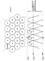
- a number of antenna beams for example 37, could be provided as determined by the fixed physical characteristics of a satellite antenna system, and used to illuminate the earth in so-called spot beam coverage regions. Some of these 37 spot beams are illustrated in Figure 1. According to conventional wisdom, the gain at the worst point, which lies midway between three spots (e.g., those indicated as corresponding to the beam illumination crossover points in Figure 1), is maximized by choosing the beam width such that the gain is approximately 3dB down at the midway point relative to the peak, beam-center gain.
- a system could employ all of the three frequency channels in every one of the 37 spot beams, with the consequence that a mobile at the midway point between three beams would receive equal overlapping signals on each frequency from all three beams, i.e., two, equal-strength interferers on top of each wanted signal, or this interference problem could be avoided by distributing the frequencies between beams in a 3-cell frequency re-use pattern.
- a mobile at the midway point between three beams would receive all three frequencies at equal strength from the three different surrounding beams, but one frequency only from each beam, with somewhat reduced interference from sidelobes of beams which are further away.
- a mobile at the midpoint between two beams would receive equal signal strength on two frequencies and somewhat reduced signal strength from two equal signals on the third frequency.
- a mobile at the center of a beam would receive principally the frequency of that beam with somewhat reduced signal strength on the other two frequencies from the six surrounding beams.
- a mobile station it is possible for a mobile station to roughly determine its position based on the relative received signal strength, e.g., on the three frequencies, as described in more detail the aforementioned U.S. Patent Application Serial No. 08/179,958.
- the following describes a more detailed, exemplary method for determining location based upon signal strengths received from nearby beams.
- the power received by a mobile from each beam depends upon the magnitude of the beam-shape, and the resulting radiation pattern of the beam is determined from a combination of the individual element radiation pattern and the array factor due to beam-forming of the elements.
- One model that can be used for determining the resulting pattern power loss is an exponential model. If there is enough discrimination from one beam to the next, then the received signal strength measured from the occupied and surrounding beams can be used as measurements of the beam-shape, which can be used to determine the mobile position.
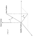
- the problem of estimating the mobile position becomes one of estimating the user position relative to the beam center.
- the user position can be specified by two angular quantities: the angle away from the beam center angle, ⁇ ; and the angle about the ray that extends from the satellite in the direction of the center of the beam, ⁇ . This concept is illustrated in Figure 2.
- This model is relatively accurate for small values of ⁇ , usually up to a few degrees.
- ⁇ the value of alpha found to approximate the array pattern after beam-forming.
- mapping x f( ⁇ , ⁇ ) is used (note that vector quantities are represented by bold typeface) and is given by: where theta is measured from the beam center.
- P [p 0 ,p 1 ,p 2 ,...,p 6 ] T .
- h i (x) can be calculated by mobile stations using the RSSI of received time slots from each of the six surrounding beams relative to a time slot received from the center beam, which measurements would then be used in equations (6) and (7).
- the estimates of the mobile position can be determined.
- Initial values are chosen for both x and k
- the beam center position can be chosen for x and k
- the assumed noise variance is chosen by assuming the worst-case signal to noise values that the technique is supposed to handle, and then choosing the appropriate noise variance of the power measurement corresponding to this signal to noise value. The noise from different beams is assumed to be independent.
- the function h(x) is given by the equation: Using this form for the position estimator allows the mobile position to be tracked over time and also produces an estimate of the estimator covariance.
- the covariance can be useful if the measured power noise variance is also estimated, in which case the estimator covariance can give better information about the accuracy of the estimated results. For example, this covariance provides an indication of the reliability of the position estimate which can be used to more accurately predict beam handover times.
- Finding the minimum point for J(x) can be accomplished in a number of different ways. Since the function h(x) is highly non-linear, an extended Kalman filtering approach can be used. Also, because of the non-linearities, the iterated extended Kalman filter approach is preferred. An equivalent form for this estimate is to calculate the Gauss-Newton estimate directly from equation (8) for each update time k.
- k -1 + ⁇ h T R -1 y ⁇ h, and g P -1 x , k
- Exemplary simulations have been performed to evaluate the present invention.
- the performance in an all-white Gaussian noise (AWGN) channel was investigated, and it is expected that this will give a bound on performance, as compared to the performance in a Rician or Rayleigh faded channel.
- the simulations were performed for QPSK signaling in an AWGN channel, and include the effects of pulse shaping and IF filters.
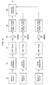
- a block diagram illustrating the simulations is shown in Figure 5.
- the block diagram illustrates that a parallel configuration was employed for the simulation wherein signals from each of seven beams were simultaneously processed by a position estimator.
- a serial implementation can be implemented wherein a single receiver successively processes signals from each of the seven beams.
- a mobile station connected to the system using one of N slots could use its idle time to process signal strength measurements according to the present invention.
- the following simulation results are based upon the model shown in Figure 5 wherein a beam source 10 for each beam produces a composite signal which is QPSK modulated at block 12.
- the modulated signal is then processed through blocks 14, 16 and 18 to model the effects of the channel on that signal.
- the position estimator 20 receives the signal and measures the received signal strengths to calculate position as described above.
- the following exemplary slot/frame format design parameters were used in a simulation, and power measurements were generated by calculating the average power in the slot corresponding to each beam.
- the noise in the power measurement was set to be a value of 0.5 (after filtering), and this was chosen to be the worst-case noise variance corresponding to a received signal/noise ratio of 2 dB.
- Parameters Exemplary Simulation Values # of antenna array beams 211 Center beam radius 150 km Reuse frequency 7/1 Exponential model ⁇ value 0.1891 Satellite orbit Intermediate circular orbit 10360 km Signal/Noise ratio 2dB Frame length 1.25 ms Channel bandwidth 200 kHz
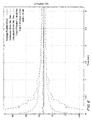
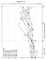
- Figure 10 and Figure 11 show the average range and bearing estimates as a function of the SNR. Each plot includes curves for different mobiles positioned from the beam center. The range error lot also shows that there may possibly be a bias in the range estimate, although more Monte-Carlo runs are required to confirm this suspicion. In any case, the bias is small and most likely due to the fact that the noise in the power measurements is not Gaussian.
- the bearing error estimates are shown to be accurate within a degree, except when the range of the mobile is close to the beam center (where the range estimate is more accurate).
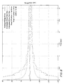
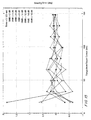
- Figure 12 and Figure 13 show the calculated standard deviation of the range and bearing estimates, respectively, as a function of the received SNR. These plots show the estimates are most accurate for high SNR values. In particular, the range estimates are most accurate for high SNR, although at distances close to the beam center the range estimate is accurate even in low SNR cases. The bearing error is most accurate for long range or high SNR cases.
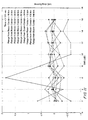
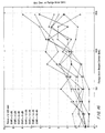
- Figures 14 and Figure 15 show the average range and bearing estimates as a function of the range from the beam center. Each plot includes curves for different SNR values, and shows that the range accuracy increases with shorter range values, while bearing accuracy increases with longer range values.
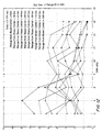
- Figures 16 and Figure 17 show the calculated standard deviation of the range and bearing estimates, respectively. Figure 16 indicates that the bias in the resulting range error is a function of range.
- Measurement of received signal strength per se is generally well known in the art of radiocommunication. Accordingly, conventional or other types of power measurement devices can be incorporated into terminals to make measurements on nearby spot beams, which measurements can then be used as input to the afore-described exemplary location algorithm.
- an analog square-law power measuring device 40 could be placed upstream of an A/D converter 42 in the received signal processing path of a terminal 44.
- power measurement could be performed in an ASIC or DSP 46 downstream of the A/D converter 42.
- a plurality of measurements can be taken and an average value, e.g., computed by averaging filter, presented to the location algorithm.
- the location algorithm can be processed either in the mobile station or in any other part of the system, e.g., base station, satellite, etc. If processing is desired in other than the mobile station, the row measurement results may be transmitted via an uplink channel to the base station or satellite. Alternatively, the base station or satellite can also be involved in performing the measurements.
- the present invention can be embodied in other specific forms.
- exemplary embodiments describe position location of terminals in the beam pointing at nadir, those skilled in the art will appreciate that the present invention can also be applied to terminals in other beams.
- position determination according to the present invention can be implemented in other types of systems. For example, land-based systems in which base stations are provided with arrays that illuminate various areas could also implement the present invention.
Landscapes
- Physics & Mathematics (AREA)
- Engineering & Computer Science (AREA)
- General Physics & Mathematics (AREA)
- Radar, Positioning & Navigation (AREA)
- Remote Sensing (AREA)
- Mobile Radio Communication Systems (AREA)
- Position Fixing By Use Of Radio Waves (AREA)
- Radio Relay Systems (AREA)
Claims (15)
- Procédé pour estimer une position d'un terminal dans un système de radiocommunication utilisant une antenne-réseau pour illuminer des zones avec des faisceaux locaux, comprenant les étapes suivantes :on mesure une puissance reçue associée à chacun d'une pluralité des faisceaux locaux;on détermine des puissances relatives associées à la puissance reçue en comparant les puissances reçues mesurées avec une puissance de référence; eton estime la position du terminal en utilisant les puissances relatives et un modèle de forme de faisceau local.
- Procédé selon la revendication 1, dans lequel l'étape de mesure est accomplie au terminal.
- Procédé selon la revendication 1, dans lequel l'étape de mesure est accomplie soit à une station de base, soit à un satellite.
- Procédé selon la revendication 2, dans lequel la puissance de référence est une puissance reçue par le terminal à partir d'un faisceau local qui illumine une région géographique dans laquelle le terminal se trouve au moment présent.
- Procédé selon la revendication 1, dans lequel les étapes de détermination et d'estimation sont accomplies dans le terminal.
- Procédé selon la revendication 1, dans lequel les étapes de détermination et d'estimation sont accomplies soit dans une station de base, soit dans un satellite.
- Procédé selon la revendication 1, dans lequel le modèle est un modèle exponentiel.
- Procédé selon la revendication 1, dans lequel l'étape de localisation comprend en outre l'étape suivante :
on itère l'équation suivante : - Procédé selon la revendication 1, dans lequel l'étape de mesure comprend en outre l'étape suivante :
on mesure simultanément chaque puissance reçue. - Procédé selon la revendication 1, dans lequel l'étape de mesure comprend en outre l'étape suivante :
on mesure chaque puissance reçue dans chacun de la pluralité de faisceaux locaux sur une fréquence différente. - Procédé selon la revendication 1, dans lequel l'étape de mesure comprend en outre l'étape suivante :
on mesure chaque puissance reçue à différents instants et on ajuste la puissance mesurée en tenant compte du mouvement d'un satellite incluant l'antenne-réseau. - Procédé pour accéder à un système de radiocommunication, comprenant :l'estimation d'une position d'un terminal par un procédé selon l'une quelconque des revendications précédentes;l'utilisation de l'emplacement estimé du terminal pour déterminer une compensation Doppler; etl'accès au système de radiocommunication en utilisant cette compensation Doppler.
- Procédé pour transférer une connexion dans un système utilisant une antenne-réseau pour fournir une couverture de radiocommunication à des zones en utilisant des faisceaux locaux, comprenant :l'estimation d'une position d'un terminal par un procédé selon l'une quelconque des revendications précédentes; etle transfert de la connexion depuis un premier faisceau local vers un second faisceau local sur la base de l'emplacement estimé.
- Procédé selon la revendication 13, dans lequel la puissance de référence est une puissance reçue par le terminal à partir du premier faisceau local qui illumine une région géographique dans laquelle le terminal se trouve au moment présent.
- Procédé selon la revendication 13, dans lequel la puissance de référence est une puissance émise par le terminal et reçue dans un premier faisceau local d'une antenne-réseau qui illumine une région géographique dans laquelle le terminal se trouve au moment présent, lorsque l'antenne-réseau est utilisée pour la réémission.
Applications Claiming Priority (3)
| Application Number | Priority Date | Filing Date | Title |
|---|---|---|---|
| US08/597,073 US6684071B1 (en) | 1994-01-11 | 1996-02-05 | Terminal position location using multiple beams |
| US597073 | 1996-02-05 | ||
| PCT/US1997/001866 WO1997028456A1 (fr) | 1996-02-05 | 1997-01-31 | Localisation de la position de terminaux a l'aide de faisceaux multiples |
Publications (2)
| Publication Number | Publication Date |
|---|---|
| EP0879423A1 EP0879423A1 (fr) | 1998-11-25 |
| EP0879423B1 true EP0879423B1 (fr) | 2001-08-01 |
Family
ID=24389980
Family Applications (1)
| Application Number | Title | Priority Date | Filing Date |
|---|---|---|---|
| EP97904247A Expired - Lifetime EP0879423B1 (fr) | 1996-02-05 | 1997-01-31 | Localisation de la position de terminaux a l'aide de faisceaux multiples |
Country Status (7)
| Country | Link |
|---|---|
| EP (1) | EP0879423B1 (fr) |
| JP (1) | JP4049224B2 (fr) |
| CN (1) | CN1210590A (fr) |
| AU (1) | AU727038B2 (fr) |
| CA (1) | CA2244993A1 (fr) |
| DE (1) | DE69705931T2 (fr) |
| WO (1) | WO1997028456A1 (fr) |
Families Citing this family (14)
| Publication number | Priority date | Publication date | Assignee | Title |
|---|---|---|---|---|
| GB9519087D0 (en) | 1995-09-19 | 1995-11-22 | Cursor Positioning Sys Ltd | Navigation and tracking system |
| GB9722324D0 (en) | 1997-10-22 | 1997-12-17 | Cambridge Positioning Sys Ltd | Positioning system for digital telephone networks |
| US6161018A (en) * | 1998-02-27 | 2000-12-12 | Motorola, Inc. | Method and system for estimating a subscriber's location in a wireless communication system service area |
| US6393294B1 (en) | 1998-09-22 | 2002-05-21 | Polaris Wireless, Inc. | Location determination using RF fingerprinting |
| GB9912724D0 (en) | 1999-06-01 | 1999-08-04 | Cambridge Positioning Sys Ltd | Radio positioning system |
| US7460505B2 (en) * | 2003-02-04 | 2008-12-02 | Polaris Wireless, Inc. | Location estimation of wireless terminals through pattern matching of signal-strength differentials |
| AU2003267888A1 (en) | 2003-09-03 | 2005-03-16 | Telefonaktiebolaget Lm Ericsson (Publ) | Method and system of positioning |
| EP1664834A1 (fr) * | 2003-09-03 | 2006-06-07 | Telefonaktiebolaget LM Ericsson (publ) | Procede et systeme de localisation |
| FI119573B (fi) * | 2007-07-11 | 2008-12-31 | 7Signal Oy | Menetelmä signaalilähteen seuraamiseksi ja paikantamiseksi radioverkossa |
| US7592956B2 (en) | 2008-02-12 | 2009-09-22 | Harris Corporation | Wireless transmitter location determining system and related methods |
| US9625573B2 (en) * | 2010-04-08 | 2017-04-18 | The Boeing Company | Geolocation leveraging spot beam overlap |
| CN102891722B (zh) * | 2011-07-21 | 2016-03-02 | 中兴通讯股份有限公司 | 一种纵向定位的方法及装置 |
| EP2748633A4 (fr) * | 2012-06-14 | 2015-04-29 | Ericsson Telefon Ab L M | Procédé et appareil pour une localisation |
| CN111273228B (zh) * | 2019-05-09 | 2023-02-07 | 哈尔滨工程大学 | 一种基于遍历搜索策略的多相干源定位方法 |
Family Cites Families (4)
| Publication number | Priority date | Publication date | Assignee | Title |
|---|---|---|---|---|
| DE4321909C2 (de) * | 1993-07-01 | 2003-02-27 | Eads Deutschland Gmbh | Antennenanordnung und Mobilfunknetz |
| US5552798A (en) * | 1994-08-23 | 1996-09-03 | Globalstar L.P. | Antenna for multipath satellite communication links |
| CN1087580C (zh) * | 1995-01-05 | 2002-07-10 | 艾利森公司 | 移动电话机的位置登记 |
| AU700251B2 (en) * | 1995-06-06 | 1998-12-24 | Globalstar L.P. | Satellite repeater diversity resource management system |
-
1997
- 1997-01-31 CN CN97192057A patent/CN1210590A/zh active Pending
- 1997-01-31 JP JP52793797A patent/JP4049224B2/ja not_active Expired - Lifetime
- 1997-01-31 DE DE69705931T patent/DE69705931T2/de not_active Expired - Lifetime
- 1997-01-31 AU AU18579/97A patent/AU727038B2/en not_active Ceased
- 1997-01-31 EP EP97904247A patent/EP0879423B1/fr not_active Expired - Lifetime
- 1997-01-31 CA CA002244993A patent/CA2244993A1/fr not_active Abandoned
- 1997-01-31 WO PCT/US1997/001866 patent/WO1997028456A1/fr not_active Ceased
Also Published As
| Publication number | Publication date |
|---|---|
| JP4049224B2 (ja) | 2008-02-20 |
| CA2244993A1 (fr) | 1997-08-07 |
| AU727038B2 (en) | 2000-11-30 |
| DE69705931D1 (de) | 2001-09-06 |
| CN1210590A (zh) | 1999-03-10 |
| AU1857997A (en) | 1997-08-22 |
| JP2000504185A (ja) | 2000-04-04 |
| WO1997028456A1 (fr) | 1997-08-07 |
| EP0879423A1 (fr) | 1998-11-25 |
| DE69705931T2 (de) | 2001-11-22 |
Similar Documents
| Publication | Publication Date | Title |
|---|---|---|
| EP0927362B1 (fr) | Determination de la position a l'aide de plusieurs signaux de station de base | |
| US7248883B2 (en) | Method and system for determining the speed and position of a mobile unit | |
| US5293642A (en) | Method of locating a mobile station | |
| US6639554B2 (en) | Apparatus and method for tracking location of mobile station | |
| US6512481B1 (en) | Communication system using geographic position data | |
| US6246874B1 (en) | Method and apparatus for predicting spot beam and satellite handover in a mobile satellite communication network | |
| EP1166144B1 (fr) | Localisation precise d'un terminal d'utilisateur dans un systeme de communications satellite | |
| EP0879423B1 (fr) | Localisation de la position de terminaux a l'aide de faisceaux multiples | |
| US6253084B1 (en) | Process and device for managing intercellular transfers of radio communications in a cellular radio communication system by measuring virtual speeds of cellular devices | |
| US6298238B1 (en) | Fast user terminal position determination in a satellite communications system | |
| US6684071B1 (en) | Terminal position location using multiple beams | |
| JPH11154897A (ja) | ドップラーシフトによって使用者端末の位置を補償する衛星通信システムおよび方法 | |
| JPH10209941A (ja) | 衛星通信システムおよび方法 | |
| US6219615B1 (en) | Satellite position fixing | |
| GB2307142A (en) | Steering an antenna in accordance with mobile location | |
| JP2001211474A (ja) | 地理位置情報の利用によるネットワークの拡張 | |
| Zhao et al. | Mobile positioning based on relaying capability of mobile stations in hybrid wireless networks | |
| O'Connor et al. | CDMA infrastructure-based location finding for E911 | |
| GB2356782A (en) | Using round trip propagation times to locate a mobile station | |
| Romdhani et al. | Mobile Location Estimation Approaches | |
| HK1121809A (en) | Fast user terminal position determination in a satellite communications system |
Legal Events
| Date | Code | Title | Description |
|---|---|---|---|
| PUAI | Public reference made under article 153(3) epc to a published international application that has entered the european phase |
Free format text: ORIGINAL CODE: 0009012 |
|
| 17P | Request for examination filed |
Effective date: 19980901 |
|
| AK | Designated contracting states |
Kind code of ref document: A1 Designated state(s): DE FR GB SE |
|
| 17Q | First examination report despatched |
Effective date: 19981207 |
|
| GRAG | Despatch of communication of intention to grant |
Free format text: ORIGINAL CODE: EPIDOS AGRA |
|
| GRAG | Despatch of communication of intention to grant |
Free format text: ORIGINAL CODE: EPIDOS AGRA |
|
| GRAG | Despatch of communication of intention to grant |
Free format text: ORIGINAL CODE: EPIDOS AGRA |
|
| GRAH | Despatch of communication of intention to grant a patent |
Free format text: ORIGINAL CODE: EPIDOS IGRA |
|
| GRAH | Despatch of communication of intention to grant a patent |
Free format text: ORIGINAL CODE: EPIDOS IGRA |
|
| GRAA | (expected) grant |
Free format text: ORIGINAL CODE: 0009210 |
|
| AK | Designated contracting states |
Kind code of ref document: B1 Designated state(s): DE FR GB SE |
|
| REF | Corresponds to: |
Ref document number: 69705931 Country of ref document: DE Date of ref document: 20010906 |
|
| ET | Fr: translation filed | ||
| REG | Reference to a national code |
Ref country code: GB Ref legal event code: IF02 |
|
| PLBE | No opposition filed within time limit |
Free format text: ORIGINAL CODE: 0009261 |
|
| STAA | Information on the status of an ep patent application or granted ep patent |
Free format text: STATUS: NO OPPOSITION FILED WITHIN TIME LIMIT |
|
| 26N | No opposition filed | ||
| PGFP | Annual fee paid to national office [announced via postgrant information from national office to epo] |
Ref country code: SE Payment date: 20080129 Year of fee payment: 12 |
|
| EUG | Se: european patent has lapsed | ||
| PG25 | Lapsed in a contracting state [announced via postgrant information from national office to epo] |
Ref country code: SE Free format text: LAPSE BECAUSE OF NON-PAYMENT OF DUE FEES Effective date: 20090201 |
|
| PGFP | Annual fee paid to national office [announced via postgrant information from national office to epo] |
Ref country code: DE Payment date: 20140129 Year of fee payment: 18 |
|
| PGFP | Annual fee paid to national office [announced via postgrant information from national office to epo] |
Ref country code: FR Payment date: 20140117 Year of fee payment: 18 |
|
| PGFP | Annual fee paid to national office [announced via postgrant information from national office to epo] |
Ref country code: GB Payment date: 20140127 Year of fee payment: 18 |
|
| REG | Reference to a national code |
Ref country code: DE Ref legal event code: R119 Ref document number: 69705931 Country of ref document: DE |
|
| GBPC | Gb: european patent ceased through non-payment of renewal fee |
Effective date: 20150131 |
|
| PG25 | Lapsed in a contracting state [announced via postgrant information from national office to epo] |
Ref country code: DE Free format text: LAPSE BECAUSE OF NON-PAYMENT OF DUE FEES Effective date: 20150801 Ref country code: GB Free format text: LAPSE BECAUSE OF NON-PAYMENT OF DUE FEES Effective date: 20150131 |
|
| REG | Reference to a national code |
Ref country code: FR Ref legal event code: ST Effective date: 20150930 |
|
| PG25 | Lapsed in a contracting state [announced via postgrant information from national office to epo] |
Ref country code: FR Free format text: LAPSE BECAUSE OF NON-PAYMENT OF DUE FEES Effective date: 20150202 |