EP0879457B1 - Vorrichtung zum erfassen von strassenfahrzeugen und signalverarbeitungsgerät dafür - Google Patents
Vorrichtung zum erfassen von strassenfahrzeugen und signalverarbeitungsgerät dafür Download PDFInfo
- Publication number
- EP0879457B1 EP0879457B1 EP97902476A EP97902476A EP0879457B1 EP 0879457 B1 EP0879457 B1 EP 0879457B1 EP 97902476 A EP97902476 A EP 97902476A EP 97902476 A EP97902476 A EP 97902476A EP 0879457 B1 EP0879457 B1 EP 0879457B1
- Authority
- EP
- European Patent Office
- Prior art keywords
- signal
- sensor
- loop
- vehicle
- magnitude
- Prior art date
- Legal status (The legal status is an assumption and is not a legal conclusion. Google has not performed a legal analysis and makes no representation as to the accuracy of the status listed.)
- Expired - Lifetime
Links
Images




Classifications
-
- G—PHYSICS
- G08—SIGNALLING
- G08G—TRAFFIC CONTROL SYSTEMS
- G08G1/00—Traffic control systems for road vehicles
- G08G1/01—Detecting movement of traffic to be counted or controlled
- G08G1/042—Detecting movement of traffic to be counted or controlled using inductive or magnetic detectors
-
- G—PHYSICS
- G08—SIGNALLING
- G08G—TRAFFIC CONTROL SYSTEMS
- G08G1/00—Traffic control systems for road vehicles
- G08G1/01—Detecting movement of traffic to be counted or controlled
Definitions
- the present invention relates to road vehicle sensing apparatus.
- a known road vehicle sensing apparatus comprises at least one sensor for location in at least one lane of a highway to detect vehicles travelling in said lane.
- a signal generation circuit is connected to the sensor and is arranged to produce a sensor signal having a magnitude which varies with time through a plurality of values as a vehicle passes the sensor in said lane. When there is no vehicle near the sensor, the signal magnitude is at a base value.
- Apparatus of this type will be referred to herein as road vehicle sensing apparatus of the type defined.
- the sensors used in road vehicle sensing apparatus of the type defined are typically inductive loops located under the road surface, which are energised to provide an inductive response to metal components of a vehicle above or near the loop. The response is usually greatest, providing a maximum sensor signal magnitude, when the maximum amount of metal is directly over the loop.
- Other types of sensor may also be employed which effectively sense the proximity of a vehicle and can provide a graduated sensor signal increasing to a maximum as the vehicle approaches and then declining again as the vehicle goes past the sensor.
- magnetometers may be used for this purpose.
- a multi lane highway with two or more traffic lanes for a single direction of travel, it is normal to provide separate sensors for each lane so that two vehicles travelling in lanes side by side can be separately counted.
- the signal generation circuit is arranged to provide a separate said signal for each sensor.
- the sensors in adjacent lanes are usually aligned across the width of the highway. Apparatus of this type with adjacent sensors in the lanes of a multi lane highway will be referred to herein as road vehicle sensing apparatus of the type defined for a multi lane highway.
- the sensor installation on a single lane of highway it is also normal practice for the sensor installation on a single lane of highway to include two sensors installed a distance apart along the lane of the highway. Again the signal generation circuit produces a separate said signal for each sensor.
- This arrangement allows the direction of travel of a vehicle in the lane to be determined and also the timing of the signals from the two sensors can be used to provide a measure of vehicle speed.
- the first sensor in the normal direction of travel in the lane can be called the entry sensor and the second sensor can be called the leaving sensor.
- Apparatus of this type will be referred to herein as vehicle sensing apparatus of the type defined with two successive sensors in a single lane.
- vehicle sensing apparatus of the type defined has been used primarily for the purpose of counting the vehicles to provide an indication of traffic density.
- the signal generation circuit of the apparatus of the type defined provides a sensor signal of varying or graduated magnitude
- a typical prior art installation has a detection threshold set at a magnitude level above the base value to provide an indication of whether or not a vehicle is being detected by the sensor.
- the only information available from the sensing apparatus is a binary signal indicating whether or not the sensor is currently detecting the vehicle, that is whether the sensor is "in detect”.
- Prior art sensing apparatus using one or more inductive loops under the road surface have signal generation circuitry arranged to energise the loops at a frequency typically in the range 60 to 90 kHz.
- a phase locked loop circuit is arranged to keep the energising frequency constant as the resonance of the loop and associated capacitance provided by the circuit is perturbed by the presence of the metal components of a road vehicle passing over the loop.
- the sensor signal produced by such signal generation circuit is typically the correction signal generated by the phase locked loop circuit required to maintain the oscillator frequency at the desired value.
- the correction signal may be a digital number contained in a correction counter.
- the digital number from the counter may progressively rise from zero count up to a maximum count (which in some examples may be between 200 and 1,000) and then falls again to zero as the vehicle moves away from the sensor loop.
- a threshold value for the sensor output signal above which the sensor is deemed to be "in detect”.
- Prior art installations are reasonably reliable and accurate in counting vehicles, so long as the traffic is free flowing along the highway with a reasonable spacing between vehicles, and so long as the vehicles do not cross from one lane to another in the vicinity of the sensor installation.
- a typical installation has a vehicle count accuracy of only about plus or minus one percent even in free flowing traffic conditions. In congested traffic conditions, count accuracy falls dramatically and is seldom specified.
- the vehicle sensing apparatus should be capable of determining the class of the vehicles using the highway, usually on the basis of vehicle length. Also, the sensor should be able to provide accurate information even in congested conditions.
- FIG. 1 illustrates a typical sensor loop illustration on a two lane carriageway of a highway.
- the normal direction of traffic on the carriageway is from left to right as shown by the arrow 10.
- Entry loop 11 and leaving loop 12 are located one after the other in the direction of travel under the surface of lane 1 of the highway and entry loop 13 and leaving loop 14 are located under lane 2.
- the entry loops 11 and 13 of the two lanes of the highway are aligned across the width of the highway and the leaving loops 12 and 14 are also aligned.
- each of the loops has a length in the direction of travel of 2 metres and the adjacent edges of the entry and leaving loops are spaced apart also by 2 metres, so that the centres of the entry and leaving loops are spaced apart by 4 metres.
- all the loops have a width of 2 metres and the adjacent entry loops 11 and 13 have neighbouring edges about 2 metres apart, with a similar spacing for the adjacent edges of the leaving loops 12 and 14.
- the various sensor loops are represented generally by the block 20.
- Each of the entry and leaving loops are connected to detector electronics 21 which provides the signal generation circuit for the various loops.
- the detector electronics may be arranged to energise each of the loops at a particularly detector station (e.g. as illustrated in Figure 1) simultaneously so that four sensor signals are then produced by the detector electronics 21 continuously representing the status of each of the loops.
- the detector electronics 21 is arranged to energise or scan each of the loops of the detector station successively, so that a sensor signal for each loop is updated on each scan at a rate determined by the scanning rate. In some examples, each sensor signal is thereby updated approximately every 6 mS.
- the raw data representing the sensor signal magnitudes are supplied from the detector electronics 21 over a serial or parallel data link to processing unit 22 in which the data is processed to derive the required traffic information. Aspects of the present invention are particularly concerned with the signal processing which may be performed by the processing unit 22.
- Processing unit 22 may be constituted by a digital data processing unit having suitable software control. It will be appreciated that many aspects of the present invention may be embodied by providing the appropriate control software for the processing unit 22.
- the illustrated installation also includes remote reporting equipment 23 arranged to receive the traffic information derived by the processing unit 22 over a serial link.
- FIG. 3 the variation in sensor signal magnitude for both entry and leaving sensor loops is illustrated graphically for a relatively short vehicle. Time is shown along the x axis and the illustrated sensor signals, or profiles, are provided assuming a vehicle has past over the entry and leaving loops at a substantially uniform speed.
- the y axis is calibrated in arbitrary units representing, in this example, the correction count contained in the phase locked loop control circuitry driving the respective loops.
- the signal profile (or signature) from the entry loop is shown at 30 and the signal profile or signature from the leaving loop is shown at 31.
- Figure 4 illustrates how the profiles from a particular loop as illustrated in Figure 3 can be normalised with respect to a maximum amplitude value.
- the sensor profile or signature has a single maximum. If this is set at a normalised value, 100, then the normalised values at the other sample points illustrated in Figure 4, can be calculated by dividing the actual magnitude value at these points by the magnitude value at the point of maximum amplitude and multiplying by one hundred. If the profile has two or more maxima or peaks, then the largest is used for normalising.
- a significant problem with sensor installations as illustrated is the possibility of double detection.
- a vehicle passing squarely over the detection loops in its own lane produces a significant sensor signal magnitude only from the loops in its lane.
- vehicle 15 will produce a significant sensor signal magnitude only in entry loop 11 and leaving loop 12 in lane 1
- vehicle 16 will produce significant sensor signals magnitudes only in entry loop 13 and leaving 14 in lane 2.
- a vehicle passing the detector site in some road position between lanes may produce substantial sensor signal magnitudes in the loops in both lanes.
- vehicle 17 will produce signal magnitudes in all four loops. This leads to a difficulty in discriminating between the case of two cars simultaneously passing over the two adjacent sets of loops (e.g.
- class cars 15 and 16 in Figure 1 and the case of a single car passing at some position between the detector loops (e.g. vehicle 17 in Figure 1).
- vehicle 17 the signal magnitude produced by this latter case (vehicle 17) would often exceed the detection thresholds of the loops in both lanes. It is important for many applications of vehicle detection that these two cases be correctly recognised.
- a single vehicle being detected in two lanes is termed a "double detection".
- the processing unit 22 in Figure 2 is arranged to measure the peak amplitudes of the signals from adjacent loops, that is the entry loops 11 and 13 or the leaving loops 12 and 14. The processing unit is then arranged to take the geometric mean of these two amplitude values and compare that mean against one or more threshold values.
- a single threshold set at a level to distinguish between double detection and genuine two vehicle detection events.
- the threshold can be set empirically.
- a single threshold may be sufficient if the adjacent loops in the two lanes are sufficiently spaced apart so that the sensor signal magnitude from adjacent loops produced by a single vehicle between the loops is likely to be relatively low in at least one of the two adjacent loops.
- two thresholds may be required, one set sufficiently low to identify clear double detection events with confidence, and the other threshold set rather higher to provide an indication of a possible double detection event.
- the processing unit is then arranged in response to a possible double detection event, where the geometric mean is only below the upper threshold and not the lower threshold, by performing other tests on the signals from the loops to confirm the likelihood of double detection.
- the further tests may include checking that the speed measured from the loop signals in the two lanes is substantially the same and also confirming that the measured length in the two lanes is substantially the same. Another check is to confirm that the signal profile from one of a pair of adjacent loops in the two lanes is contained fully within the profile from the other loop.
- the length of the vehicle passing over a sensor site can be determined by measuring properties of the signal profile or signature obtained from one or both of the entry and leaving loops.
- the length may be determined either dynamically, requiring a knowledge of the vehicle speed, or statically.
- Static measurements have an advantage over dynamic measurements in that they can be made in stop-start traffic conditions, while dynamic measurements require vehicle speed to be reasonably constant while passing over the sensor site. On the other hand dynamic measurements can in some cases be more accurate and reliable.
- One dynamic method for determining speed relies on measuring the time between points on the leading and trailing edges of the sensor signal profile as a vehicle passes a sensor loop.
- the processing unit may be arranged to determine the time between predefined points on the leading and trailing edges.
- the predefined points may be points of inflexion on these edges.
- a point of inflexion is defined as the point of maximum gradient.
- One method of determining the timing of the points of inflexion on the leading and trailing edges is by determining the times at either side of the inflexion point where the signature slope is somewhat less than its maximum and then finding the mid point between these upper and lower points. This method is used to avoid the effect of transient distortions of the signal profile, which may for example be caused by suspension movement of the vehicle travelling over the sensor. A transient distortion could result in a single measurement of the point of maximum slope being incorrect. Several measurements could be taken at different slopes on either side of the inflexion point and then a central tendency calculation applied to these measurements to obtain the inflexion point times to be used for calculating the length of the vehicle.
- the signal magnitude data available from the sensing apparatus may not be available continuously but only at regular time intervals corresponding to the scanning rate of the sensor energising electronics. This can produce quantisation effects so that it is not possible to obtain the timing of precise slope values on the signal profile.
- Time infl Time low + ( Time high - Time low ) 2 + ( Slope high - Slope low ) ( Slope low + Slope high ) ⁇ Time quantisation
- time differences can be determined from the signal profiles of both the entry and leaving loops of an installation such as illustrated in Figure 1.
- the vehicle speed In order to determine a value for the length of the vehicle from the elapsed time measurement made as above, it is necessary to know the vehicle speed. This may be provided separately by some other speed sensing device, e.g. a radar device synchronised with the loop sensors. However, more preferably, the speed will be derived also from tne loop sensor signals in various ways as will be described later herein.
- a radar device synchronised with the loop sensors.
- the speed will be derived also from tne loop sensor signals in various ways as will be described later herein.
- the signal processing unit may instead be arranged to measure the time between points on the respective edges at which the sensor signal has a magnitude which is a predetermined fraction of the nearest adjacent high signal magnitude.
- the "high signal magnitude” is defined as the magnitude at the nearest minimum in the modulus of the gradient of the profile.
- the first point at which the modulus of the gradient reduces to a minimum value and then rises again is in fact at the maximum amplitude of the signal profile. At this point, of course, the modulus of the slope falls to zero before it rises again (as the slope becomes negative).
- the signal profiles generated by larger vehicles may have one or more "shoulders" in the leading or trailing edges of the profiles, such as is shown in the leading edge of the profile illustrated in Figure 6.
- These shoulders occur in larger vehicles because the vehicle is magnetically non uniform.
- the shoulder may represent a point in the signal profile where a first peak would have occurred, but the influence of a more distant but magnetically larger element of the vehicle approaching the sensor loop has overwhelmed the local effect on the loop. It has been found desirable in determining the length of such vehicles from the leading and trailing edges of the signal profile produced, to take account of these initial effects resulting from the front or rear of the vehicle first entering or leaving the sensor loop.
- a shoulder is taken into consideration only if it involves a significant reduction in the slope of the edge, to approximately 25% or less than the maximum slope on the edge, and if the shoulder point is at a signal magnitude that is a substantial portion of the nearest signal peak, approximately 65% or more. Also the shoulder is taken into consideration only if the slope is of significant duration for example continues to be less than 35% of the maximum slope for at least 15% of the total duration of the edge up to the first peak. Also, it is important that the shoulder is detected in the signal profiles from both the entry and leaving loops.
- the magnitude of the signal value at the shoulder (the high signal magnitude) is taken to be the magnitude at the point of minimum slope on the shoulder.
- the selected points on the leading and trailing edges between which the time duration is measured are selected to have magnitudes which are the same fraction of the nearest peak or shoulder.
- the time duration is determined between a first point at time t leading25 and a second point at time t trailing25.
- the first point is when the signal magnitude on the leading edge reaches 25% of the magnitude at the shoulder 60.
- the second point is when the signal magnitude on the trailing edge declines to 25% of the magnitude at the adjacent peak 61.
- the length of the vehicle is then taken to be the time between these two points (t length25 ) multiplied by the measured speed of the vehicle.
- 25% is considered to be a fraction which can best relate to precisely when the front or rear of a vehicle crosses the centre point of the respective loop. If other fractions are used to determine the time measuring points, corrections may be built in to the calculation used for the length. The most appropriate fraction and correction to be used can be determined empirically. Further empirically derived corrections may be made to the calculated length as required. Also, the time spacing between points at several different fractions of the nearest peak or shoulder on the leading and trailing edges of a single profile can be measured and each corrected in accordance with appropriate empirically derived factors and constants. The various length measurements thereby determined can then be combined to provide a measure of central tendency. In addition measurements may be made from the sensor signal profiles from both the entry and leaving loops.
- a shoulder or a maximum amplitude value in a signal profile is used in the calculation only if it is found to be present in the signals from both the entry and leaving loops. For this purpose, if the normalised magnitude at the shoulder or peak is within 10% of the same value in the profiles from the two loops, then the shoulders or peaks in the two profiles are considered matched.
- the length of a vehicle from a single signal profile by deriving empirically a function which relates the shape of the profile to vehicle length. It is necessary to normalise the signal profile relative to the amplitude of the highest peak of the profile.
- the signal processing unit can then be arranged to determine the normalised magnitude values of the signal profile at a series of times along the profile which, knowing the speed of the vehicle, corresponds to predetermined equal distances in the vehicle direction of travel. These normalised magnitude values at the predetermined incremental distances along the profile can then be inserted into the empirically derived function stored in the processing unit in order to derive a value for the vehicle length.
- Another method of determining the length of a vehicle uses the signal profiles from both the entry and leaving loops.
- the entry and leaving loops 70 and 71 are shown overlapping at a time eq . It has been found that the value of the magnitude of the profiles at the point in time when these magnitudes are equal is approximately linearly related to the length of vehicle.
- the normalised profile magnitudes are used to find the point of equality on overlap of the trailing and leading edges.
- the equal magnitude point illustrated in Figure 7 is at 28% of the peak amplitude of each of the profiles 70 and 71.
- the processing unit is arranged to record magnitude values from the two sensor loops at least over the full trailing edge of the signal from the entry loop and the full leading edge of the signal from the leaving loop. Then the necessary calculations can be done to normalise the magnitude values once all the values have been recorded, irrespective of the speed of the vehicle and the corresponding time taken for the signals to decline back to the base value.
- the above described method of determining the vehicle length can work only in cases where the trailing edge of the entry loop signal and the leading edge of the leaving loop signal do in fact overlap to produce an intersection point. This will generally occur only for relatively shorter vehicles.
- the minimum vehicle length which can be measured in this way corresponds to the minimum vehicle length which continues to produce a signal in both the entry and leaving loops as the vehicle travels between the two. If the vehicle is too short there is a point at which there is no signal detected in either loop so that, as shown in Figure 9, the trailing and leading edges of the two profiles do not overlap. This corresponds to level eq from the above equation being zero.
- the maximum vehicle length which can be measured is as represented in Figure 8 where the last amplitude peak in the signal profile from the entry sensor coincides with the first amplitude peak of the signal profile from the leaving sensor, so that again there is no point of intersection between the trailing and leading edges of the profiles. This corresponds to level eq having the value 1 in the above equation.
- the above method is capable of measuring vehicle lengths only between three and up to about seven metres. Nevertheless, for shorter or longer vehicles, the method can still provide an indication of the maximum or minimum length respectively.
- This method relies on the empirical knowledge of the spacing of the entry and leaving loop centres and that the leading edge of a signal profile between the point of first detection of a vehicle and the first maximum amplitude (or substantial shoulder as defined before) corresponds to a reasonably predictable total distance of movement of the front of the vehicle for any particular installation.
- a vehicle is first detected when the front of the vehicle is typically 1 metre from the centre of the entry loop, that is approximately over the front edge of the entry loop.
- the signal from the loop has a normalised magnitude of 25% of the adjacent peak amplitude.
- the signal magnitude reaches 75% of the peak when the front of the vehicle is aligned over the rear edge of the entry loop and the first peak in the profile is reached when the front of the vehicle is 1 metre beyond the rear edge of the loop, in fact at the mid point between the entry and leaving loops of the installation of Figure 1.
- the processing unit is arranged to record the magnitude values of the sensor signals from both the entry and leaving sensors.
- the magnitude values for the two profiles recorded at substantially the same times are correlated.
- the processing unit is then further arranged to provide a profile correlating function which can compare the profile of the entry and leaving loop signals to identify points on the profile of one loop which correspond in terms of profile position to points on the profile from the other loop. This is possible because the processing unit has a record of the signal magnitude value for both profiles. It is therefore straightforward for the processing unit to track through its record of magnitude values for one profile to identify a point in the profile which corresponds to any particular point in the other profile.
- the corresponding point 85 on the leaving loop profile can be determined by profile correlation. It should be understood that, whereas point 82 is time correlated with point 83, i.e. was recorded at the same time, point 85 is profile correlated with point 82, i.e. was recorded at a different time but is in the corresponding position in the two profiles.
- the shift between the points 82 and 85 corresponds to a shift along the length of the vehicle equal to the distance between the centres of the entry and leaving loops, 4 metres in the example of Figure 1.
- the point 85 on the leaving loop profile corresponds to a position where the centre of the leaving loop is 4 metres from the front of the vehicle.
- the processing means can now perform a repeat time correlation to identify the time correlated point 86 on the entry loop profile which was recorded at the same time as point 85 on the leaving loop profile.
- This newly identified point 86 on the entry loop profile may again be profile correlated with a point 87 on the leaving loop profile.
- This point 87 now corresponds to the centre of the leaving loop being 8 metres from the front of the vehicle.
- the point 87 may again be time correlated with a point 88 on the entry loop profile and the point 88 once again profile correlated with a point 89 on the leaving loop profile.
- This point 89 now corresponds to the centre of the leaving loop being 12 metres from the front of the vehicle.
- One further iteration of time correlation to point 90 and profile correlation to point 91 identifies a point on the leaving loop profile which corresponds to the front of the vehicle being 16 metres in front of the centre of the leaving loop.
- the processing unit can determine that point 91 is in fact on the trailing edge of the leaving loop profile and can also determine the normalised magnitude of the point 91 relative to the immediately preceding peak amplitude on the profile. For example, in the example of Figure 10, point 91 is at approximately 46% of the amplitude at peak 92.
- the processing unit can make a further calculation to determine an additional length component to be added to the 16 metres already determined for the length of the vehicle.
- the overall length of the vehicle can be calculated as 16.42 metres.
- An additional constant correction may be applied derived by empirical testing.
- the above procedure may be repeated for a number of different starting positions on the leading edge of the leaving loop, with an appropriate correction being made for the empirically derived position of the point of starting the measurement from the centre of the leaving loop.
- the various measurements derived may be combined to obtain a value for the central tendency.
- the process has been explained by starting with a predetermined point on the leading edge of the leaving loop, the process could also be performed by starting with a predetermined position on the trailing edge of the entry loop and working forward in time along the profiles until reaching a point on the leading edge of the entry loop.
- the above procedure can be performed irrespective of the speed of the vehicle.
- the profile correlation can be performed using only the way in which the magnitude values of each of the two profiles varies.
- FIG. 11 A further static method for determining vehicle lengths is illustrated in Figure 11.
- the processing means is arranged to record the magnitude values for the profiles from the entry and leaving loops 95 and 96, at least from the amplitude peak or high signal magnitude of the entry loop profile 95 over the trailing edge of the profile, and over the leading edge of the leaving loop profile 96 up to its first amplitude peak or high signal magnitude. Then, the normalised magnitude values in the trailing and leading edges of the two profiles at a number of different time points are measured. These pairs of normalised magnitude values taken at individual time points can be used directly to derive a value for the length of the vehicle.
- the time points are determined to correspond with predetermined normalised amplitude values on one of the two edges. Then it is necessary only to record the normalised magnitude values at these time points on the other of the two edges and use these values in an empirically derived function to provide a value for the vehicle length.
- normalised magnitude values are measured on the trailing edge of the entry loop profile 95 at times corresponding to normalised magnitude values on the leading edge of the leaving loop profile 96 of 10%, 20%, 30%, etc. up to 100%.
- the 10% magnitude value on the leaving loop profile 96 produces sample 1 from the trailing edge of the entry loop
- the 20% value produces sample 2 and so forth.
- any samples are taken at a time earlier than the last peak of the profile, then these samples are set at a normalised height of 1.0 (100%) in order to reduce the complexity of the transfer function used. This can occur, for example, if the two profiles in Figure 11 are closer together so that the 10% sample from the leading edge of profile 96 corresponds to a point on profile 95 before the peak of the profile.
- the above described static methods of measuring vehicle lengths may be particularly useful in traffic monitoring in high congestion conditions. It is also important that the entry loop of a detection loop pair is cleared ready for a subsequent vehicle detection event as soon as the signal profile from the loop has declined substantially to zero, even if the signal from the leaving loop of the pair is still high.
- the processing unit is arranged to capture all the data from the entry loop and hold this data available for appropriate comparisons with the data from the leaving loop once this becomes available. The processing unit is simultaneously then able to record fresh signal data from the entry loop, which would correspond to a following vehicle, even while still receiving data from the leaving loop corresponding to the preceding vehicle.
- the signal processing unit records all the signal magnitude data from the two sensors of a road vehicle sensing apparatus of the type defined with two successive sensors, and includes means for processing this data to derive vehicle characteristic information once all the data has been received and recorded.
- the processing unit can be arranged to separately record data from the entry sensor corresponding to a second vehicle, whilst still recording data from the trailing sensor corresponding to the first vehicle.
- the signal processing unit is also arranged to record all the signal magnitude data from the sensors in all lanes, for subsequent processing as required.
- a further important characteristic of a useful road vehicle sensing apparatus is to be able to identify gaps between vehicles travelling very close together so that tailgating vehicles can be separated even when their sensor profiles overlap.
- One method of detecting tailgating involves the processing unit monitoring a characteristic of the profiles of signals from the entry and leaving sensors and comparing the characteristic of a profile from the entry sensor with the characteristic in the next following profile from the leaving sensor and providing a tailgating indication if there is a substantial difference between these characteristics.
- the selected characteristic may be the signal magnitude at a minimum in the profile from the two sensors.
- the processing unit is arranged to consider minima only if they satisfy this criterion.
- Tailgating may also be detected if there is a minimum in the profile from the entry loop satisfying the required criterion and where the profile from the leaving loop drops substantially to zero before rising again. This corresponds to the case where two vehicles are close together when passing over the entry loop but the first vehicle clears the leaving loop before the second vehicle is detected by the leaving loop.
- Tailgating may also be indicated if there is a substantial minimum in the profile from the leaving loop even though the profile from the entry loop had previously dropped to zero. This would correspond to the case where a vehicle has past normally over the entry loop, clearing it before a second vehicle is detected by the entry loop, but the second vehicle then comes very close to the first vehicle before the first vehicle clears the leaving loop.
- the threshold for detecting a minimum in this particular case lower than the predetermined threshold used for detecting tailgating when minima are found in the profiles from both loops. This is necessary to avoid indicating tailgating when a single vehicle having a minimum in its profile which would be normally slightly above the main threshold used for both the entry and leaving loops but is transiently below this threshold as the vehicle passes the leaving loop, e.g. due to suspension movement or other variables between the two loops.
- the main threshold used for detecting minima in both entry and leaving loops can be made dependent on traffic speed.
- a level of 30% of the profile maximum amplitude may be satisfactory as a minimum detection threshold at low speeds, dropping to zero at speeds in excess of 7 metres per second. This can achieve a high vehicle count accuracy in most conditions.
- To reduce the minimum detection threshold at higher vehicle speeds is not essential for operation of the tailgating detection algorithm, but can slightly improve count accuracies at these higher speeds.
- An approximate speed value can be determined by measuring the time between different predetermined normalised magnitude levels on the leading or trailing slope of a signal profile. For example, in the installation illustrated in Figure 1, it has been shown empirically that for most vehicles, the difference on the leading edge of a profile between the signal magnitude of 25% of the nearest peak (or high level) and 75% corresponds to movement of the front of a vehicle by 1 metre. Thus, if the time between the attainment of these two values on the leading edge of a profile is measured, the approximate speed of a vehicle can be determined directly. Different calculations can be made for different selected threshold levels and in different installations.
- the time difference can be measured between corresponding features in the signal profiles from the entry and leaving loops. Knowing the spacing of the loops in a particular installation, the speed can be calculated directly.
- the road vehicle sensing apparatus produces sensor signal values at discrete sampling times, corresponding to the scanning rate between the various loops of the installation. Then, the actual time of occurrence of a particular feature in a signal profile is indeterminate by plus or minus half the sampling period (which may be 6 mS or more). This can represent a speed measurement error of about ⁇ 21 ⁇ 2% at 70 mph using a base line corresponding to the spacing of the centres of the entry and leaving sensors of 4 metres.
- the second factor introducing errors is that transient distortions of the signal profile can cause a particular profile feature being used for the speed measurement to appear slightly before or after its correct time.
- the first of these factors can be addressed by interpolating between individual signal magnitude level samples received at the sampling rate, to discover the correct timing for a particular feature (e.g. a required magnitude value).
- a particular feature e.g. a required magnitude value
- ordinary linear interpolation can be used to find the correct time between two samples on either side of the desired magnitude.
- T feature T 1 + (T 2 - T 1 ) ⁇ ( S 1 - S 2 ) ( S 1 + S 2 ) ⁇ 2
- multiple matched profile features can be used from the two loop profiles. For example, multiple levels on leading and trailing profile edges can be timed relative to corresponding levels on the edges of the other profile and a speed measurement obtained for each matched pair. Then error theory can be used to determine the central tendency of the resulting values.
- the invention contemplated herein is constituted not only by a signal processing apparatus for processing said signals from a road vehicle sensing apparatus of the type defined preferably for a multi lane highway and with two successive sensors in each single lane, but is also constituted by a road vehicle sensing apparatus in combination with the signal processing apparatus described.
- the system takes data from loop detectors, conditions the data via a Loop state machine if required, and processes the data from loop pairs in each lane to determine events that represent the passage of vehicles over each lane's detector site.
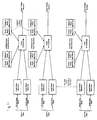
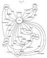
- the purposes of each element in Figure 12 are:
- the input data is normally samples of the output from the loop detectors taken at regular intervals, although other presentations can be provided.
- the output data depends on the nature of the application, but may be:
- data is received and conditioned by the Loop state machines, and passed to the event state machine for examinination.
- Event state machines There are multiple event state machines simultaneously available for each lane, and several may be actively processing events in each lane at any time.
- the need for multiple machines can be understood by mentally following the progress of vehicles over the detection site.
- two vehicles travelling close one behind the other in a lane As the first passes over the site and is proceeding over the exit loop, the second may already be starting to pass over the entry loop.
- an Event state machine Since the purpose of an Event state machine is to track the progress of a vehicle from entry onto the site until it is completely clear of the site, it can be seen that in this case two state machines are required. One is handling the vehicle currently moving off the site, and one the vehicle currently moving onto the site.
- Event state machines particularly where there are more than two lanes in a carriageway.
- a three lane carriageway that there is a long vehicle with three cars at its side, and all are straddling lanes because of an obstruction. It is not possible to be sure that the truck is not several tailgating vehicles until it has completely passed over the detection site, and all of the cars alongside must remain part of the double detection configuration until the last of the four vehicles is off the site, when the whole configuration can be fully evaluated. All of the state machines must remain active until this time, so more are needed.
- the operation of the Event state machines depend on the data presented, previous data presented, the states of the state machines handling the lanes on either side, the mode of the system, and the state of the loop detectors.
- the Lane Processing module directs loop data to the appropriate state machine under direction from the Event state machines themselves, which decide which loops in a lane each should be receiving data from, depending on the signature presented.
- the Event state machines are associated with a Tailgate state machine when they are active, and pass information to their Tailgate state machine so that it can determine if tailgating is occurring.
- the relevent information is the locations of maxima and minima in the data, and when the loops drop out of detection.
- Tailgate state machine determines that tailgating is occurring, it will split the signatures obtained by its associated Event state machine at the appropriate point. Frequently it will be necessary for a Tailgate state machine to find an unused Event state machine to move part of the signature to. It then sets the states of the Event state machines to be compatible with the new view of the data and directs loop data to the appropriate Event state machine. Following this the processing of data proceeds as normal.
- Event and Tailgate state machines Following sections describe the operation of Event and Tailgate state machines.
- the loop state machine is not described because it is dependent on the particular detectors used.
- FIGS 13A and 13B from the transition diagram for the Event State Machine.
- Figure 14 forms the transition diagram for the Tailgate State Machine.
Landscapes
- Physics & Mathematics (AREA)
- General Physics & Mathematics (AREA)
- Traffic Control Systems (AREA)
- Radar Systems Or Details Thereof (AREA)
- Geophysics And Detection Of Objects (AREA)
- Train Traffic Observation, Control, And Security (AREA)
- Road Signs Or Road Markings (AREA)
Claims (31)
- Signalverarbeitungsvorrichtung zum Verarbeiten von Sensorsignalen von einer Straßenfahrzeug-Abtastvorrichtung des Typs mit benachbarten Sensoren in den Spuren einer mehrspurigen Straße, wobei jeder Sensor mit einer Signalerzeugungsschaltung verbunden und jeweils zum Erzeugen eines Sensorsignals ausgebildet ist, das eine Stärke hat, die sich zeitlich über eine Vielzahl von Werten ändert, während ein Fahrzeug den Sensor in seiner Spur passiert, wobei das Signal auf einem Grundwert ist, wenn sich kein Fahrzeug in der Nähe von dem Sensor befindet, wobei die Signalverarbeitungsvorrichtung folgendes aufweist:eine Einrichtung, die so ausgebildet ist, daß sie den Zeitablauf von Sensorsignalen überwacht, die von Sensoren in benachbarten Spuren einer Straße erzeugt werden, und eine Anzeige liefert, wenn diese Sensorsignale einer Doppelzählung entsprechen könnten, wobei von beiden Sensoren ein einziges Fahrzeug detektiert wird, undeine Einrichtung, die so ausgebildet ist, daß sie auf diese Anzeige von der Überwachungseinrichtung anspricht, um das geometrische Mittel der Amplituden der Sensorsignale von den Sensoren in benachbarten Spuren zu errechnen und eine Doppelzählungsanzeige zu liefern, wenn das geometrische Mittel einen vorbestimmten Grenzwert unterschreitet.
- Signalverarbeitungsvorrichtung nach Anspruch 1,
wobei die zum Ansprechen ausgebildete Einrichtung ferner so ausgebildet ist, daß sie eine Anzeige einer wahrscheinlichen Doppelzählung liefert, wenn das geometrische Mittel den vorbestimmten Grenzwert überschreitet, aber unter einem höheren vorbestimmten Grenzwert liegt, und
wobei die Vorrichtung weiterhin eine zusätzliche Prüfeinrichtung aufweist, die auf die Anzeige der wahrscheinlichen Doppelzählung anspricht, um eine Prüfung in bezug auf eine Doppelzählung auszuführen. - Signalverarbeitungsvorrichtung nach Anspruch 2,
wobei die zusätzliche Prüfeinrichtung so ausgebildet ist, daß sie eine Doppelzählung bestätigt, wenn nach Berücksichtigung einer Zeitablaufdifferenz, die der Tatsache entspricht, daß die benachbarten Sensoren über die Breite der Straße nicht ausgefluchtet sind, die Hüllkurve des Sensorsignals von dem einen Sensor vollständig in der Hüllkurve des Signals von dem anderen Sensor enthalten ist. - Signalverarbeitungsvorrichtung nach einem der vorhergehenden Ansprüche, die folgendes aufweist:eine Zeitgebereinrichtung, die so ausgebildet ist, daß sie eine Anzeige der Zeitdauer zwischen vordefinierten Punkten an der vorderen Flanke und der hinteren Flanke eines Sensorsignals liefert, das durch ein am Sensor vorbeifahrendes Fahrzeug erzeugt wird, undeine Recheneinrichtung, die so ausgebildet ist, daß sie einen Wert für die Länge des Fahrzeugs aus dem Produkt der Zeitdauer und einem Wert für die Geschwindigkeit des Fahrzeugs errechnet.
- Signalverarbeitungsvorrichtung nach Anspruch 4,
wobei die Zeitgebereinrichtung so ausgebildet ist, daß die vordefinierten Punkte jeweils Punkte eines maximalen Gradienten an den jeweiligen Flanken sind. - Signalverarbeitungsvorrichtung nach Anspruch 4,
wobei die Zeitgebereinrichtung so ausgebildet ist, daß die vordefinierten Punkte jeweils Punkte an den jeweiligen Flanken sind, bei denen das Sensorsignal einen Wert hat, der ein vorbestimmter Bruchteil des nächstbenachbarten hohen Signalwertes ist, wobei der nächstbenachbarte hohe Signalwert als Wert bei dem nächsten Minimum in dem Modul des Gradienten angenommen wird. - Signalverarbeitungsvorrichtung nach Anspruch 6,
wobei die Zeitgebereinrichtung so ausgebildet ist, daß sie ein nächstbenachbartes Minimum vernachlässigt, bei dem der minimale Gradient mehr als 25 % des maximalen Gradienten in der jeweiligen Flanke beträgt. - Signalverarbeitungsvorrichtung nach Anspruch 6 oder 7,
wobei die Zeitgebereinrichtung so ausgebildet ist, daß sie ein nächstliegendes Minimum vernachlässigt, bei dem die Signalstärke weniger als 65 % der Stärke an dem nächstliegenden Maximalpunkt beträgt, an dem der Gradient Null ist. - Signalverarbeitungsvorrichtung nach einem der Ansprüche 6 bis 8,
wobei die Zeitgebereinrichtung so ausgebildet ist, daß sie ein nächstliegendes Minimum vernachlässigt, bei dem der Gradient nicht weniger als 35 % des maximalen Gradienten in der jeweiligen Flanke für wenigstens 15 % der Dauer der Flanke beträgt. - Signalverarbeitungsvorrichtung nach einem der Ansprüche 6 bis 9,
wobei die Zeitgebereinrichtung so ausgebildet ist, daß der vorbestimmte Bruchteil in dem Bereich von 25 % bis 75 % liegt. - Signalverarbeitungsvorrichtung nach einem der vorhergehenden Ansprüche, die folgendes aufweist:eine Aufzeichnungseinrichtung, die so ausgebildet ist, daß sie Größenwerte für ein Sensorsignal aufzeichnet, die in einer Vielzahl von Intervallen während des Vorbeifahrens eines Fahrzeugs an dem Sensor aufgenommen werden,eine Einrichtung, die so ausgebildet ist, daß sie einen Wert für die Geschwindigkeit des Fahrzeugs liefert, wobei die Intervalle im Zusammenhang mit dem Geschwindigkeitswert so gewählt sind, daß sie Positionen entsprechen, die vorbestimmte Abstände entlang dem Fahrzeug haben,eine Recheneinrichtung, die so ausgebildet ist, daß sie Werte für die aufgezeichneten Größen errechnet, die relativ zu der Maximalamplitude des Sensorsignals normiert sind,eine Speichereinrichtung, die eine empirisch abgeleitete Funktion enthält, die die normierten aufgezeichneten Größenwerte zu der Länge eines Fahrzeugs, das das Sensorsignal erzeugt, in Beziehung setzt, undeine Verarbeitungseinrichtung, die so ausgebildet ist, daß sie aus der Funktion und den normierten Werten einen Wert für die Länge des Fahrzeugs ableitet.
- Signalverarbeitungsvorrichtung nach Anspruch 11,
wobei die Recheneinrichtung so ausgebildet ist, daß sie bestimmt, ob das Sensorsignal jeweilige separate Maxima angrenzend an die vordere Flanke und die hintere Flanke des Signals hat, und dann die aufgezeichneten Werte für jedes der Intervalle zwischen diesen Maxima auf die Größe von einem der Maxima einstellt. - Signalverarbeitungsvorrichtung nach einem der vorhergehenden Ansprüche,
wobei zwei aufeinanderfolgende Sensoren in einer einzelnen Spur vorhanden sind, wobei die Signalverarbeitungsvorrichtung folgendes aufweist:eine Einrichtung, die so ausgebildet ist, daß sie die hintere Flanke des Signals von dem Eintrittssensor und die vordere Flanke des Signals von dem Austrittssensors während des Vorbeifahrens eines Fahrzeugs an den Sensoren überwacht und einen Wert für die Signalgröße zu dem Zeitpunkt bestimmt, zu dem die Größenwerte in der hinteren Flanke und der vorderen Flanke im wesentlichen gleich sind, undeine Recheneinrichtung, die so ausgebildet ist, daß sie aus dem bestimmten Signalgrößenwert einen Wert für die Länge des Fahrzeugs errechnet. - Signalverarbeitungsvorrichtung nach Anspruch 13,
wobei die zum Überwachen ausgebildete Einrichtung ferner so ausgebildet ist, daß sie Größenwerte für das Sensorsignal von dem Eintrittssensor wenigstens aus dem Maximum dieses Signals über der hinteren Flanke aufzeichnet, Größenwerte für das Sensorsignal von dem Austrittssensor wenigstens über der vorderen Flanke zu dem Maximum des Signals aufzeichnet, den zeitlichen Verlauf der aufgezeichneten Werte von den beiden Sensoren korreliert, die aufgezeichneten Werte für jedes der Sensorsignale relativ zu dem aufgezeichneten Maximum des jeweiligen Sensorsignals normiert, und den normierten Wert zu dem Zeitpunkt bestimmt, zu dem die normierten aufgezeichneten Werte in der hinteren Flanke und der vorderen Flanke im wesentlichen gleich sind, und wobei die Recheneinrichtung aus dem bestimmten normierten Wert den Längenwert errechnet. - Signalverarbeitungsvorrichtung nach Anspruch 13,
wobei die zum Überwachen ausgebildete Einrichtung so ausgebildet ist, daß sie den tatsächlichen Signalgrößenwert bestimmt, wenn die Werte in den Flanken gleich sind, und die Recheneinrichtung den Längenwert aus dem bestimmten tatsächlichen Wert und der Maximalamplitude von mindestens einem der Sensorsignale errechnet. - Signalverarbeitungsvorrichtung nach einem der vorhergehenden Ansprüche,
wobei aufeinanderfolgende Sensoren in einer einzelnen Spur vorhanden sind und wobei die Verarbeitungsvorrichtung zur Verwendung beim Bestimmen von Werten für die Längen von an den Sensoren vorbeifahrenden Fahrzeugen dient, wenn die Fahrzeuge lang genug sind, um sich gleichzeitig vollständig über beide Sensoren zu erstrekken, wobei ein erster hoher Punkt in dem Signal von dem Austrittssensor vor dem letzten hohen Punkt in dem Signal von dem Eintrittssensor auftritt, und wobei ein hoher Punkt als ein Minimum in dem Modul des Gradienten des Signals definiert ist, wobei die Vorrichtung folgendes aufweist:wobei die Zeitkorrelationseinrichtung ferner so ausgebildet ist, daß sie die Profil-korrelierten Punkte an dem ersten Sensorsignal wiederholt mit zeitlich korrelierten Punkten an dem zweiten Sensorsignal korreliert, und wobei die Profilkorrelationseinrichtung ferner so ausgebildet ist, daß sie die weiteren zeitlich korrelierten Punkte an dem zweiten Sensorsignal wiederholt mit entsprechenden Punkten an dem Profil des ersten Sensorsignals korreliert, bis Punkte über das gesamte Profil des ersten Sensorsignals korreliert sind,eine Aufzeichnungseinrichtung, die so ausgebildet ist, daß sie Größenwerte für die Sensorsignale von jedem von dem Eintritts- und dem Austrittssensor aufzeichnet und die Werte von dem einen Sensor mit den gleichzeitig aufgezeichneten Werten von dem anderen Sensor korreliert,eine Erkennungseinrichtung zum Identifizieren von wenigstens einem Punkt an einer vorderen Flanke des Signals von dem Austrittssensor oder an der hinteren Flanke des Signals von dem Eintrittssensor, wobei von diesem Punkt empirisch bekannt ist, daß er jeweils einer vorbestimmten Position der Vorderseite des Fahrzeugs relativ zu dem Austrittssensor oder der Rückseite des Fahrzeugs relativ zu dem Eintrittssensor entspricht,eine Zeitkorrelationseinrichtung, die so ausgebildet ist, daß sie den erkannten Punkt an dem jeweiligen vorgenannten Sensorsignal (dem ersten Sensorsignal) mit einem zeitlich korrelierten Punkt an dem anderen der Sensorsignale (dem zweiten Sensorsignal) korreliert,eine Profilkorrelationseinrichtung, die so ausgebildet ist, daß sie den zeitlich korrelierten Punkt an dem zweiten Sensorsignal mit einem entsprechenden Punkt an dem Profil des ersten Sensorsignals korreliert, der für das Fahrzeug, das die äquivalenten Positionen in bezug auf die beiden Sensoren hat, repräsentativ ist,und eine Recheneinrichtung, die so ausgebildet ist, daß sie einen Wert für die Fahrzeuglänge aus der empirisch bekannten vorbestimmten Position, dem bekannten Abstand zwischen dem Eintritts- und dem Austrittssensor und der Anzahl Korrelationen durch die Profilkorrelationseinrichtung errechnet. - Signalverarbeitungsvorrichtung nach Anspruch 16,
die eine Korrektureinrichtung aufweist, die so ausgebildet ist, daß sie den Größenwert des letzten Punkts normiert, der von der Profilkorrelationseinrichtung an dem ersten Sensorsignal relativ zu dem nächsten hohen Punkt in dem Signal korreliert worden ist, und den errechneten Längenwert um einen Betrag korrigiert, der von der Differenz zwischen der normierten Größe und einer empirisch bestimmten Referenzgröße abhängig ist. - Signalverarbeitungsvorrichtung nach einem der vorhergehenden Ansprüche,
wobei zwei aufeinanderfolgende Sensoren in einer einzelnen Spur vorhanden sind, wobei die Vorrichtung folgendes aufweist:eine Aufzeichnungseinrichtung, die so ausgebildet ist, daß sie beim Vorbeifahren eines Fahrzeugs an den Sensoren Größenwerte für das Sensorsignal von dem Eintrittssensor zumindest über der hinteren Flanke des Signals von dem angrenzenden hohen Punkt, an dem ein Minimum in dem Modul des Gradienten des Signals vorhanden ist, aufzeichnet, daß sie Größenwerte für das Sensorsignal von dem Austrittssensor zumindest über der vorderen Flanke des Signals zu dem angrenzenden hohen Punkt aufzeichnet und daß sie den Zeitpunkt der aufgezeichneten Werte von den beiden Sensoren korreliert,eine Normierungseinrichtung, die so ausgebildet ist, daß sie die aufgezeichneten Größenwerte für jedes Sensorsignal relativ zu der Größe des angrenzenden hohen Punkts des jeweiligen Signals normiert,eine Wähleinrichtung zum Auswählen einer Vielzahl von Punkten entweder an der hinteren Flanke des Eintrittssensorsignals oder der vorderen Flanke des Austrittssensorsignals (der genannten einen Flanke), wobei die ausgewählten Punkte vorbestimmte normierte Signalgrößen haben,eine Korrelationseinrichtung, die so ausgebildet ist, daß sie die ausgewählten Punkte an der einen Flanke mit zeitlich korrelierten Punkten an der anderen Flanke korreliert und die normierten Größenwerte der zeitlich korrelierten Punkte erkennt, undeine Recheneinrichtung, die so ausgebildet ist, daß sie eine empirisch abgeleitete Funktion benutzt, um einen Wert für die Länge des Fahrzeugs aus den erkannten normierten Größenwerten zu errechnen. - Signalverarbeitungsvorrichtung nach einem der vorhergehenden Ansprüche,
wobei zwei aufeinanderfolgende Sensoren in einer Spur vorhanden sind, wobei die Vorrichtung folgendes aufweist:eine Überwachungseinrichtung, die so ausgebildet ist, daß sie mindestens eine Charakteristik der Profile von Signalen von dem Eintritts- und dem Austrittssensor überwacht, undeine Vergleichseinrichtung, die so ausgebildet ist, daß sie die überwachte Charakteristik eines Signalprofils von dem Eintrittssensor mit dem nächstfolgenden Signalprofil von dem Austrittssensor vergleicht und eine Anzeige für zu dichtes Auffahren liefert, wenn die überwachten Charakteristiken in den Profilen hinreichend verschieden sind, um anzuzeigen, daß die beiden Profile nicht von einem einzigen Fahrzeug erzeugt worden ist. - Signalverarbeitungsvorrichtung nach Anspruch 19,
wobei die Überwachungseinrichtung so ausgebildet ist, daß sie die Anwesenheit des Größenwerts bei einem Signalminimum jedes Profils bestimmt und mißt, so daß der Größenwert bei dem Minimum die genannte Charakteristik bildet. - Signalverarbeitungsvorrichtung nach Anspruch 20,
wobei die Vergleichseinrichtung so ausgebildet ist, daß sie eine Anzeige für zu dichtes Auffahren liefert, wenn in dem Signalprofil von den Eintrittssensoren ein Signalminimum detektiert wird, aber das anschließende Profil von dem Austrittssensor von seinem Maximum direkt auf die Größe Null fällt, bevor es wieder ansteigt. - Signalverarbeitungsvorrichtung nach Anspruch 20 oder 21,
wobei die Vergleichseinrichtung so ausgebildet ist, daß sie die normierten Größen bei jedem Signalminimum relativ zu der Maximalamplitude des jeweiligen Signals errechnet und die normierten Größen bei Minima vergleicht. - Signalverarbeitungsvorrichtung nach Anspruch 22,
wobei die Überwachungseinrichtung so ausgebildet ist, daß sie die Anwesenheit eines Signalminimums nur dann bestimmt, wenn die normierte Größe unter einen ersten vorbestimmten Grenzwert fällt und dann erneut über einen zweiten vorbestimmten Grenzwert ansteigt, der über dem ersten Grenzwert liegt. - Signalverarbeitungsvorrichtung nach Anspruch 23,
wobei die Vergleichseinrichtung so ausgebildet ist, daß sie eine Anzeige für zu dichtes Auffahren liefert, wenn ein Signalminimum nur in dem Signalprofil von dem Austrittssensor detektiert wird. - Signalverarbeitungsvorrichtung nach Anspruch 24,
wobei die Vergleichseinrichtung so ausgebildet ist, daß sie die Anzeige für zu dichtes Auffahren nur dann liefert, wenn das nur in dem Profil von dem Austrittssensor detektierte Signalminimum eine normierte Größe unter einem dritten vorbestimmten Grenzwert hat, der niedriger als der erste Grenzwert ist. - Signalverarbeitungsvorrichtung nach einem der Ansprüche 23 bis 25,
die eine Geschwindigkeitseinrichtung aufweist, die so ausgebildet ist, daß sie aus einem Sensorsignal einen Wert für die Geschwindigkeit des den Sensor passierenden Fahrzeugs bestimmt, und wobei die Überwachungseinrichtung so ausgebildet ist, daß sie den ersten Grenzwert für höhere Geschwindigkeitswerte reduziert. - Signalverarbeitungsvorrichtung nach Anspruch 26,
wobei die Geschwindigkeitseinrichtung so ausgebildet ist, daß sie die Zeitdauer mißt, die zwischen vorbestimmten normierten Größen an der vorderen Flanke eines Signalprofils verstreicht, und daß sie den Geschwindigkeitswert aus der verstrichenen Zeitdauer und einer empirisch bestimmten Strecke errechnet, die den vorbestimmten normierten Größen entspricht. - Signalverarbeitungsvorrichtung nach einem der vorhergehenden Ansprüche,
die folgendes aufweist:eine Aufzeichnungseinrichtung, die so ausgebildet ist, daß sie dann, wenn ein Fahrzeug den Sensor passiert, Größenwerte für das Sensorsignal zumindest über der vorderen Flanke des Signals zu dem angrenzenden hohen Punkt, an dem ein Minimum in dem Modul des Gradienten des Signals vorhanden ist, aufzeichnet und den relativen zeitlichen Ablauf der aufgezeichneten Größenwerte aufzeichnet,eine Normierungseinrichtung, die so ausgebildet ist, daß sie die aufgezeichneten Größenwerte relativ zu der Größe des angrenzenden hohen Punkts normiert,eine Zeitgebereinrichtung, die so ausgebildet ist, daß sie aus dem aufgezeichneten relativen zeitlichen Ablauf die verstrichene Zeitdauer zwischen zwei vorbestimmten normierten Größenwerten unter den normierten aufgezeichneten Werten bestimmt, undeine Recheneinrichtung, die so ausgebildet ist, daß sie aus der verstrichenen Zeitdauer und einer empirisch bestimmten Strecke, die den vorbestimmten normierten Größenwerten entspricht, einen Wert für die Geschwindigkeit des Fahrzeugs errechnet. - Signalverarbeitungsvorrichtung nach einem der vorhergehenden Ansprüche,
wobei zwei aufeinanderfolgende Sensoren in einer Spur vorhanden sind, wobei die Signalerzeugungsschaltung der Erfassungsvorrichtung wirksam ist zur Bildung von diskreten Sensorsignalgrößenwerten in regelmäßigen zeitlichen Abständen, die einer Abtastrate der Schaltung entsprechen, wobei die Signalverarbeitungsvorrichtung folgendes aufweist:eine Zeitgebereinrichtung, die so ausgebildet ist, daß sie die verstrichene Zeitdauer zwischen entsprechenden Punkten in den jeweiligen Größenprofilen der beiden Sensorsignale beim Vorbeifahren eines Fahrzeugs an dem Eintritts- und dem Austrittssensor mißt, undeine Recheneinrichtung, die so ausgebildet ist, daß sie einen Wert für die Geschwindigkeit des Fahrzeugs aus der verstrichenen Zeitdauer und der bekannten Strecke zwischen den Sensoren errechnet, wobei die Zeitgebereinrichtung ferner so ausgebildet ist, daß sie zwischen Zeitpunkten, die den regelmäßigen zeitlichen Abständen entsprechen, interpoliert. - Signalverarbeitungsvorrichtung nach Anspruch 29,
wobei die entsprechenden Punkte in den jeweiligen Größenprofilen Punkte mit einem ausgewählten Größenwert an entsprechenden vorderen und hinteren Flanken der Profile von den beiden Sensoren sind, und wobei die Zeitgebereinrichtung so ausgebildet ist, daß sie den zeitlichen Ablauf an mindestens einem der Punkte bestimmt durch Erkennen der diskreten Sensorsignalgrößenwerte auf beiden Seiten des ausgewählten Werts und die Unterschiede zwischen diesen diskreten Werten und dem ausgewählten Wert zum Errechnen eines Bruchteils des regelmäßigen Zeitintervalls durch lineare Interpolation nutzt. - Signalverarbeitungsvorrichtung nach einem der vorhergehenden Ansprüche,
wobei zwei aufeinanderfolgende Sensoren in einer Spur vorhanden sind, wobei die Vorrichtung folgendes aufweist:eine Zeitgebereinrichtung, die so ausgebildet ist, daß sie die verstrichene Zeitdauer zwischen entsprechenden Punkten in den jeweiligen Größenprofilen der beiden Sensorsignale beim Vorbeifahren eines Fahrzeugs an dem Eintritts- und dem Austrittssensor mißt, undeine Recheneinrichtung, die so ausgebildet ist, daß sie einen Wert für die Geschwindigkeit des Fahrzeugs aus der verstrichenen Zeitdauer und der bekannten Strecke zwischen den Sensoren errechnet, wobei die Zeitgebereinrichtung so ausgebildet ist, daß sie die verstrichenen Zeitdauern für eine Vielzahl von verschiedenen Paaren der entsprechenden Punkte mißt, und die Recheneinrichtung so ausgebildet ist, daß sie die zentrale Tendenz dieser Vielzahl von verstrichenen Zeitdauern zum Errechnen eines zuverlässigeren Geschwindigkeitswerts benutzt.
Priority Applications (3)
| Application Number | Priority Date | Filing Date | Title |
|---|---|---|---|
| EP10177978A EP2276010A1 (de) | 1996-02-06 | 1997-02-05 | Fahrzeugsdetektionsanlage und Signalsverarbeitungsanlage dafür |
| EP05076452A EP1585081A3 (de) | 1996-02-06 | 1997-02-05 | Fahrzeugsdetektionsanlage und Signalsverarbeitungsanlage dafür |
| EP00201284A EP1028404B1 (de) | 1996-02-06 | 1997-02-05 | Fahrzeugsdetektionsanlage und Signalsverarbeitungsanlage dafür |
Applications Claiming Priority (3)
| Application Number | Priority Date | Filing Date | Title |
|---|---|---|---|
| GB9602378 | 1996-02-06 | ||
| GBGB9602378.3A GB9602378D0 (en) | 1996-02-06 | 1996-02-06 | Road vehicle sensing apparatus and signal processing apparatus therefor |
| PCT/GB1997/000323 WO1997029468A1 (en) | 1996-02-06 | 1997-02-05 | Road vehicle sensing apparatus and signal processing apparatus therefor |
Related Child Applications (1)
| Application Number | Title | Priority Date | Filing Date |
|---|---|---|---|
| EP00201284A Division EP1028404B1 (de) | 1996-02-06 | 1997-02-05 | Fahrzeugsdetektionsanlage und Signalsverarbeitungsanlage dafür |
Publications (2)
| Publication Number | Publication Date |
|---|---|
| EP0879457A1 EP0879457A1 (de) | 1998-11-25 |
| EP0879457B1 true EP0879457B1 (de) | 2000-10-25 |
Family
ID=10788201
Family Applications (4)
| Application Number | Title | Priority Date | Filing Date |
|---|---|---|---|
| EP97902476A Expired - Lifetime EP0879457B1 (de) | 1996-02-06 | 1997-02-05 | Vorrichtung zum erfassen von strassenfahrzeugen und signalverarbeitungsgerät dafür |
| EP10177978A Withdrawn EP2276010A1 (de) | 1996-02-06 | 1997-02-05 | Fahrzeugsdetektionsanlage und Signalsverarbeitungsanlage dafür |
| EP05076452A Withdrawn EP1585081A3 (de) | 1996-02-06 | 1997-02-05 | Fahrzeugsdetektionsanlage und Signalsverarbeitungsanlage dafür |
| EP00201284A Expired - Lifetime EP1028404B1 (de) | 1996-02-06 | 1997-02-05 | Fahrzeugsdetektionsanlage und Signalsverarbeitungsanlage dafür |
Family Applications After (3)
| Application Number | Title | Priority Date | Filing Date |
|---|---|---|---|
| EP10177978A Withdrawn EP2276010A1 (de) | 1996-02-06 | 1997-02-05 | Fahrzeugsdetektionsanlage und Signalsverarbeitungsanlage dafür |
| EP05076452A Withdrawn EP1585081A3 (de) | 1996-02-06 | 1997-02-05 | Fahrzeugsdetektionsanlage und Signalsverarbeitungsanlage dafür |
| EP00201284A Expired - Lifetime EP1028404B1 (de) | 1996-02-06 | 1997-02-05 | Fahrzeugsdetektionsanlage und Signalsverarbeitungsanlage dafür |
Country Status (12)
| Country | Link |
|---|---|
| US (1) | US6345228B1 (de) |
| EP (4) | EP0879457B1 (de) |
| AT (2) | ATE308093T1 (de) |
| AU (1) | AU1611497A (de) |
| BR (1) | BR9707364B1 (de) |
| CA (1) | CA2247372C (de) |
| DE (2) | DE69703382D1 (de) |
| ES (2) | ES2154023T3 (de) |
| GB (1) | GB9602378D0 (de) |
| GR (1) | GR3035262T3 (de) |
| PT (1) | PT879457E (de) |
| WO (1) | WO1997029468A1 (de) |
Families Citing this family (47)
| Publication number | Priority date | Publication date | Assignee | Title |
|---|---|---|---|---|
| US7426437B2 (en) * | 1997-10-22 | 2008-09-16 | Intelligent Technologies International, Inc. | Accident avoidance systems and methods |
| US7629899B2 (en) | 1997-10-22 | 2009-12-08 | Intelligent Technologies International, Inc. | Vehicular communication arrangement and method |
| US8965677B2 (en) | 1998-10-22 | 2015-02-24 | Intelligent Technologies International, Inc. | Intra-vehicle information conveyance system and method |
| US8255144B2 (en) * | 1997-10-22 | 2012-08-28 | Intelligent Technologies International, Inc. | Intra-vehicle information conveyance system and method |
| US9558663B2 (en) | 2000-10-04 | 2017-01-31 | Intelligent Technologies International, Inc. | Animal detecting and notification method and system |
| US8989920B2 (en) | 2000-09-08 | 2015-03-24 | Intelligent Technologies International, Inc. | Travel information sensing and communication system |
| US6758089B2 (en) * | 2001-07-09 | 2004-07-06 | Intelligent Technologies International Inc. | Wireless sensing and communication system of roadways |
| US9014953B2 (en) | 2000-09-08 | 2015-04-21 | Intelligent Technologies International, Inc. | Wireless sensing and communication system for traffic lanes |
| US6973462B2 (en) * | 2001-04-03 | 2005-12-06 | Florida Atlantic University | Integrated guardianship information system |
| US7026955B2 (en) * | 2001-07-12 | 2006-04-11 | Scott Kauffman | Apparatus and method for activating an inductance loop vehicle detection system |
| US7764197B2 (en) * | 2001-10-17 | 2010-07-27 | United Toll Systems, Inc. | System and synchronization process for inductive loops in a multilane environment |
| US7136828B1 (en) | 2001-10-17 | 2006-11-14 | Jim Allen | Intelligent vehicle identification system |
| US7324015B1 (en) * | 2001-10-17 | 2008-01-29 | Jim Allen | System and synchronization process for inductive loops in a multilane environment |
| US7734500B1 (en) | 2001-10-17 | 2010-06-08 | United Toll Systems, Inc. | Multiple RF read zone system |
| US8331621B1 (en) | 2001-10-17 | 2012-12-11 | United Toll Systems, Inc. | Vehicle image capture system |
| US7725348B1 (en) * | 2001-10-17 | 2010-05-25 | United Toll Systems, Inc. | Multilane vehicle information capture system |
| US6864804B1 (en) | 2001-10-17 | 2005-03-08 | Jim Allen | Ferromagnetic loop |
| WO2003077531A2 (en) * | 2002-03-08 | 2003-09-18 | Inductive Signature Technologies, Inc. | Normalization of inductive vehicle detector outputs |
| GB2389947B (en) * | 2002-07-25 | 2004-06-02 | Golden River Traffic Ltd | Automatic validation of sensing devices |
| JP4098027B2 (ja) * | 2002-08-01 | 2008-06-11 | 松下電器産業株式会社 | 無線基地局装置 |
| GB2385138B (en) * | 2002-10-02 | 2004-02-04 | Golden River Traffic Ltd | Verification of loop sensing devices |
| US20040236474A1 (en) * | 2003-02-27 | 2004-11-25 | Mahesh Chowdhary | Vehicle management system |
| DE10323144A1 (de) * | 2003-05-22 | 2004-12-09 | Robert Bosch Gmbh | Verfahren und Vorrichtung zur Detektion von Objekten in der Umgebung eines Fahrzeugs |
| US7079632B2 (en) * | 2003-08-28 | 2006-07-18 | International Business Machines Corporation | Voice mail profiles for dynamic voice mail response |
| US7116248B2 (en) * | 2003-11-20 | 2006-10-03 | Reno A & E | Vehicle detector system with synchronized operation |
| US7482916B2 (en) | 2004-03-15 | 2009-01-27 | Anita Au | Automatic signaling systems for vehicles |
| US7089790B2 (en) * | 2004-10-18 | 2006-08-15 | Silverbrook Research Pty Ltd | Pressure sensor with laminated membrane |
| US7327238B2 (en) * | 2005-06-06 | 2008-02-05 | International Business Machines Corporation | Method, system, and computer program product for determining and reporting tailgating incidents |
| US7782228B2 (en) * | 2005-11-07 | 2010-08-24 | Maxwell David C | Vehicle spacing detector and notification system |
| US7952021B2 (en) | 2007-05-03 | 2011-05-31 | United Toll Systems, Inc. | System and method for loop detector installation |
| US8868220B2 (en) * | 2007-07-16 | 2014-10-21 | Crucs Holdings, Llc | Systems and methods for automatically changing operational states of appliances |
| US9076331B2 (en) * | 2007-07-16 | 2015-07-07 | Crucs Holdings, Llc | System and method to monitor vehicles on a roadway and to control driving restrictions of vehicle drivers |
| US9997068B2 (en) | 2008-01-28 | 2018-06-12 | Intelligent Technologies International, Inc. | Method for conveying driving conditions for vehicular control |
| US8417441B2 (en) | 2008-07-18 | 2013-04-09 | Sensys Networks, Inc. | Method and apparatus generating and/or using estimates of arterial vehicular movement |
| DE102010013878A1 (de) * | 2010-02-16 | 2011-08-18 | Niechoj electronic GmbH, 88085 | Fahrbahnintegrierter Radarsensor |
| WO2012015453A1 (en) * | 2010-07-29 | 2012-02-02 | Sensys Networks, Inc. | Sensor nodes acting as inductive loops for traffic sensing |
| ES2377613B1 (es) * | 2010-08-02 | 2013-02-01 | Universidad Carlos Iii De Madrid | Método para caracterizar el tráfico rodado. |
| US8990032B2 (en) | 2010-12-30 | 2015-03-24 | Sensys Networks, Inc. | In-pavement wireless vibration sensor nodes, networks and systems |
| JP6007395B2 (ja) * | 2012-03-13 | 2016-10-12 | 株式会社創発システム研究所 | 交通検知システム |
| WO2014134558A1 (en) | 2013-02-28 | 2014-09-04 | Naztec, Inc. | Wireless vehicle detection system and associated methods having enhanced response time |
| US9061686B2 (en) * | 2013-10-29 | 2015-06-23 | Ford Global Technologies, Llc | Road grade estimation for a trailered vehicle |
| GB2536028B (en) * | 2015-03-05 | 2018-05-09 | Red Fox Id Ltd | Vehicle detection apparatus with inductive loops |
| GB2564882B (en) * | 2017-07-25 | 2022-04-13 | Red Fox Id Ltd | Apparatus and methods for assessing vehicles straddled between lanes |
| US11151874B2 (en) * | 2020-01-23 | 2021-10-19 | Frogparking Limited | Vehicle flow monitoring system |
| US11351999B2 (en) | 2020-09-16 | 2022-06-07 | Xuan Binh Luu | Traffic collision warning device |
| ES2823373B8 (es) * | 2020-12-18 | 2023-10-26 | Univ Valencia Politecnica | Sistema y metodo de monitorizacion de vehiculos de movilidad personal en entornos urbanos |
| US12358518B2 (en) * | 2021-09-24 | 2025-07-15 | Embark Trucks, Inc. | Autonomous vehicle automated scenario characterization |
Family Cites Families (20)
| Publication number | Priority date | Publication date | Assignee | Title |
|---|---|---|---|---|
| US3863206A (en) * | 1974-03-12 | 1975-01-28 | Lee C Rabie | Digital Vehicle Detector |
| US3943339A (en) * | 1974-04-29 | 1976-03-09 | Canoga Controls Corporation | Inductive loop detector system |
| US3983531A (en) * | 1974-06-10 | 1976-09-28 | Northern Traffic & Signal Systems Ltd. | Vehicle-responsive signal means |
| US3984764A (en) * | 1975-03-03 | 1976-10-05 | Canoga Controls Corporation | Inductive loop structure for detecting the presence of vehicles over a roadway |
| NL184645C (nl) * | 1979-08-09 | 1989-09-18 | Philips Nv | Werkwijze voor het bepalen van de snelheid van een voertuig. |
| FR2480973A1 (fr) * | 1980-04-21 | 1981-10-23 | Electronique Vehicules Reseaux | Dispositif de signalisation routiere fonction de la vitesse et des dimensions des vehicules |
| US4568937A (en) * | 1982-06-03 | 1986-02-04 | Microsense Systems, Limited | Induction loop vehicle detector |
| US4680717A (en) * | 1984-09-17 | 1987-07-14 | Indicator Controls Corporation | Microprocessor controlled loop detector system |
| GB8432807D0 (en) * | 1984-12-31 | 1985-02-06 | Emx International Ltd | Loop data link |
| US4943805A (en) * | 1986-11-13 | 1990-07-24 | Dennison James L | Conduit-enclosed induction loop for a vehicle detector |
| US5089815A (en) * | 1987-05-08 | 1992-02-18 | Detector Systems, Inc. | Vehicle communication system using existing roadway loops |
| JPH0554085A (ja) | 1991-08-28 | 1993-03-05 | Fuji Xerox Co Ltd | 動画像検索支援装置 |
| US5408179A (en) * | 1991-09-26 | 1995-04-18 | Sampey Scientific, Ltd. | Method and apparatus for analying traffic and a sensor therefor |
| US5455768A (en) * | 1992-11-06 | 1995-10-03 | Safetran Traffic Systems, Inc. | System for determining vehicle speed and presence |
| US5491475A (en) * | 1993-03-19 | 1996-02-13 | Honeywell Inc. | Magnetometer vehicle detector |
| US6208268B1 (en) * | 1993-04-30 | 2001-03-27 | The United States Of America As Represented By The Secretary Of The Navy | Vehicle presence, speed and length detecting system and roadway installed detector therefor |
| US5648904A (en) * | 1994-04-25 | 1997-07-15 | Sony Corporation | Vehicle traffic system and method |
| US5512891A (en) * | 1994-05-04 | 1996-04-30 | H. M. Electronics, Inc. | Drive-up station vehicle detection system and method of using same |
| US5751225A (en) * | 1994-09-12 | 1998-05-12 | Minnesota Mining And Manufacturing Company | Vehicle detector system with presence mode counting |
| US5617086A (en) * | 1994-10-31 | 1997-04-01 | International Road Dynamics | Traffic monitoring system |
-
1996
- 1996-02-06 GB GBGB9602378.3A patent/GB9602378D0/en active Pending
-
1997
- 1997-02-05 BR BRPI9707364-4A patent/BR9707364B1/pt not_active IP Right Cessation
- 1997-02-05 EP EP97902476A patent/EP0879457B1/de not_active Expired - Lifetime
- 1997-02-05 AT AT00201284T patent/ATE308093T1/de not_active IP Right Cessation
- 1997-02-05 DE DE69703382T patent/DE69703382D1/de not_active Expired - Lifetime
- 1997-02-05 CA CA002247372A patent/CA2247372C/en not_active Expired - Lifetime
- 1997-02-05 DE DE69734474T patent/DE69734474T2/de not_active Expired - Lifetime
- 1997-02-05 PT PT97902476T patent/PT879457E/pt unknown
- 1997-02-05 WO PCT/GB1997/000323 patent/WO1997029468A1/en not_active Ceased
- 1997-02-05 EP EP10177978A patent/EP2276010A1/de not_active Withdrawn
- 1997-02-05 ES ES97902476T patent/ES2154023T3/es not_active Expired - Lifetime
- 1997-02-05 AU AU16114/97A patent/AU1611497A/en not_active Abandoned
- 1997-02-05 ES ES00201284T patent/ES2250070T3/es not_active Expired - Lifetime
- 1997-02-05 EP EP05076452A patent/EP1585081A3/de not_active Withdrawn
- 1997-02-05 EP EP00201284A patent/EP1028404B1/de not_active Expired - Lifetime
- 1997-02-05 US US09/117,726 patent/US6345228B1/en not_active Expired - Lifetime
- 1997-02-05 AT AT97902476T patent/ATE197202T1/de not_active IP Right Cessation
-
2001
- 2001-01-17 GR GR20010400082T patent/GR3035262T3/el unknown
Also Published As
| Publication number | Publication date |
|---|---|
| ES2154023T3 (es) | 2001-03-16 |
| EP0879457A1 (de) | 1998-11-25 |
| GB9602378D0 (en) | 1996-04-03 |
| DE69703382D1 (de) | 2000-11-30 |
| WO1997029468A1 (en) | 1997-08-14 |
| DE69734474D1 (de) | 2005-12-01 |
| EP1585081A3 (de) | 2011-01-12 |
| BR9707364B1 (pt) | 2009-01-13 |
| DE69734474T2 (de) | 2006-07-27 |
| BR9707364A (pt) | 1999-07-20 |
| EP1585081A2 (de) | 2005-10-12 |
| GR3035262T3 (en) | 2001-04-30 |
| EP2276010A1 (de) | 2011-01-19 |
| EP1028404A3 (de) | 2003-10-15 |
| ES2250070T3 (es) | 2006-04-16 |
| CA2247372C (en) | 2006-08-15 |
| EP1028404B1 (de) | 2005-10-26 |
| ATE308093T1 (de) | 2005-11-15 |
| CA2247372A1 (en) | 1997-08-14 |
| AU1611497A (en) | 1997-08-28 |
| US6345228B1 (en) | 2002-02-05 |
| EP1028404A2 (de) | 2000-08-16 |
| ATE197202T1 (de) | 2000-11-15 |
| PT879457E (pt) | 2001-04-30 |
Similar Documents
| Publication | Publication Date | Title |
|---|---|---|
| EP1028404B1 (de) | Fahrzeugsdetektionsanlage und Signalsverarbeitungsanlage dafür | |
| Petty et al. | Accurate estimation of travel times from single-loop detectors | |
| US7145475B2 (en) | Predictive automatic incident detection using automatic vehicle identification | |
| AU2001253856A1 (en) | Automatic incident detection | |
| EP0470268B1 (de) | Verkehrsmonitorvorrichtung | |
| US3675195A (en) | Apparatus for detecting traffic information | |
| JP2893544B2 (ja) | 異常交通流の検出装置 | |
| JP3328437B2 (ja) | 旅行時間決定方法 | |
| JP3086643B2 (ja) | 車両走行情報収集装置 | |
| JP3734594B2 (ja) | 異常事象検出装置および交通流計測装置 | |
| KR100661902B1 (ko) | 루프식 차량감지장치에서의 차량 검지방법 | |
| KR102423140B1 (ko) | 차량검지 시스템 및 그의 제어 방법 | |
| EP3652719B1 (de) | Vorrichtung und verfahren zur beurteilung von grätschsitzfahrzeugen zwischen fahrspuren | |
| EP2084689B1 (de) | Verfahren und vorrichtung zum bestimmen des abstands zwischen zwei auf einer strasse oder einem autobahnabschnitt fahrenden fahrzeugen insbesondere in einem tunnel | |
| JP3602226B2 (ja) | 通過車両台数計測方法および装置 | |
| US20240201007A1 (en) | Distributed optical fiber sensing (dfos) system and method of using the same | |
| JPH02196399A (ja) | 突発事象検出装置 | |
| JP2596554B2 (ja) | 車種判別方法 | |
| JPH0449498A (ja) | 走行車両の車種判別及び速度計測方法並びにそのための装置 | |
| KR100312211B1 (ko) | 초음파 교통량 검지기를 이용한 차량 정보 획득 방법 | |
| JPH03231183A (ja) | 移動物体の存在検出方法および装置 | |
| CN120977123A (zh) | 基于全量过车数据的路口信号控制效果评价方法及系统 | |
| JPS62154200A (ja) | 交通情報収集装置 | |
| JPS58207405A (ja) | 道路における事故検出方法 |
Legal Events
| Date | Code | Title | Description |
|---|---|---|---|
| PUAI | Public reference made under article 153(3) epc to a published international application that has entered the european phase |
Free format text: ORIGINAL CODE: 0009012 |
|
| 17P | Request for examination filed |
Effective date: 19980728 |
|
| AK | Designated contracting states |
Kind code of ref document: A1 Designated state(s): AT BE CH DE DK ES FI FR GB GR IE IT LI NL PT SE |
|
| 17Q | First examination report despatched |
Effective date: 19990312 |
|
| GRAG | Despatch of communication of intention to grant |
Free format text: ORIGINAL CODE: EPIDOS AGRA |
|
| GRAG | Despatch of communication of intention to grant |
Free format text: ORIGINAL CODE: EPIDOS AGRA |
|
| GRAH | Despatch of communication of intention to grant a patent |
Free format text: ORIGINAL CODE: EPIDOS IGRA |
|
| GRAH | Despatch of communication of intention to grant a patent |
Free format text: ORIGINAL CODE: EPIDOS IGRA |
|
| GRAA | (expected) grant |
Free format text: ORIGINAL CODE: 0009210 |
|
| AK | Designated contracting states |
Kind code of ref document: B1 Designated state(s): AT BE CH DE DK ES FI FR GB GR IE IT LI NL PT SE |
|
| PG25 | Lapsed in a contracting state [announced via postgrant information from national office to epo] |
Ref country code: NL Free format text: LAPSE BECAUSE OF FAILURE TO SUBMIT A TRANSLATION OF THE DESCRIPTION OR TO PAY THE FEE WITHIN THE PRESCRIBED TIME-LIMIT Effective date: 20001025 Ref country code: LI Free format text: LAPSE BECAUSE OF FAILURE TO SUBMIT A TRANSLATION OF THE DESCRIPTION OR TO PAY THE FEE WITHIN THE PRESCRIBED TIME-LIMIT Effective date: 20001025 Ref country code: IT Free format text: LAPSE BECAUSE OF FAILURE TO SUBMIT A TRANSLATION OF THE DESCRIPTION OR TO PAY THE FEE WITHIN THE PRE;WARNING: LAPSES OF ITALIAN PATENTS WITH EFFECTIVE DATE BEFORE 2007 MAY HAVE OCCURRED AT ANY TIME BEFORE 2007. THE CORRECT EFFECTIVE DATE MAY BE DIFFERENT FROM THE ONE RECORDED.SCRIBED TIME-LIMIT Effective date: 20001025 Ref country code: FR Free format text: LAPSE BECAUSE OF FAILURE TO SUBMIT A TRANSLATION OF THE DESCRIPTION OR TO PAY THE FEE WITHIN THE PRESCRIBED TIME-LIMIT Effective date: 20001025 Ref country code: FI Free format text: LAPSE BECAUSE OF FAILURE TO SUBMIT A TRANSLATION OF THE DESCRIPTION OR TO PAY THE FEE WITHIN THE PRESCRIBED TIME-LIMIT Effective date: 20001025 Ref country code: CH Free format text: LAPSE BECAUSE OF FAILURE TO SUBMIT A TRANSLATION OF THE DESCRIPTION OR TO PAY THE FEE WITHIN THE PRESCRIBED TIME-LIMIT Effective date: 20001025 Ref country code: BE Free format text: LAPSE BECAUSE OF FAILURE TO SUBMIT A TRANSLATION OF THE DESCRIPTION OR TO PAY THE FEE WITHIN THE PRESCRIBED TIME-LIMIT Effective date: 20001025 Ref country code: AT Free format text: LAPSE BECAUSE OF FAILURE TO SUBMIT A TRANSLATION OF THE DESCRIPTION OR TO PAY THE FEE WITHIN THE PRESCRIBED TIME-LIMIT Effective date: 20001025 |
|
| REF | Corresponds to: |
Ref document number: 197202 Country of ref document: AT Date of ref document: 20001115 Kind code of ref document: T |
|
| REG | Reference to a national code |
Ref country code: CH Ref legal event code: EP |
|
| REG | Reference to a national code |
Ref country code: IE Ref legal event code: FG4D |
|
| REF | Corresponds to: |
Ref document number: 69703382 Country of ref document: DE Date of ref document: 20001130 |
|
| PG25 | Lapsed in a contracting state [announced via postgrant information from national office to epo] |
Ref country code: SE Free format text: LAPSE BECAUSE OF FAILURE TO SUBMIT A TRANSLATION OF THE DESCRIPTION OR TO PAY THE FEE WITHIN THE PRESCRIBED TIME-LIMIT Effective date: 20010125 Ref country code: DK Free format text: LAPSE BECAUSE OF FAILURE TO SUBMIT A TRANSLATION OF THE DESCRIPTION OR TO PAY THE FEE WITHIN THE PRESCRIBED TIME-LIMIT Effective date: 20010125 |
|
| PG25 | Lapsed in a contracting state [announced via postgrant information from national office to epo] |
Ref country code: DE Free format text: LAPSE BECAUSE OF FAILURE TO SUBMIT A TRANSLATION OF THE DESCRIPTION OR TO PAY THE FEE WITHIN THE PRESCRIBED TIME-LIMIT Effective date: 20010126 |
|
| REG | Reference to a national code |
Ref country code: ES Ref legal event code: FG2A Ref document number: 2154023 Country of ref document: ES Kind code of ref document: T3 |
|
| EN | Fr: translation not filed | ||
| NLV1 | Nl: lapsed or annulled due to failure to fulfill the requirements of art. 29p and 29m of the patents act | ||
| REG | Reference to a national code |
Ref country code: PT Ref legal event code: SC4A Free format text: AVAILABILITY OF NATIONAL TRANSLATION Effective date: 20010112 Ref country code: CH Ref legal event code: PL |
|
| PLBE | No opposition filed within time limit |
Free format text: ORIGINAL CODE: 0009261 |
|
| 26N | No opposition filed | ||
| REG | Reference to a national code |
Ref country code: GB Ref legal event code: IF02 |
|
| REG | Reference to a national code |
Ref country code: PT Ref legal event code: PC4A Owner name: 3M INNOVATIVE PROPERTIES COMPANY, US Effective date: 20130109 |
|
| REG | Reference to a national code |
Ref country code: ES Ref legal event code: PC2A Owner name: 3M INNOVATIVE PROPERTIES COMPANY Effective date: 20130121 |
|
| REG | Reference to a national code |
Ref country code: GB Ref legal event code: 732E Free format text: REGISTERED BETWEEN 20130124 AND 20130130 |
|
| PGFP | Annual fee paid to national office [announced via postgrant information from national office to epo] |
Ref country code: IE Payment date: 20160209 Year of fee payment: 20 Ref country code: ES Payment date: 20160113 Year of fee payment: 20 |
|
| PGFP | Annual fee paid to national office [announced via postgrant information from national office to epo] |
Ref country code: GR Payment date: 20160114 Year of fee payment: 20 Ref country code: PT Payment date: 20160205 Year of fee payment: 20 Ref country code: GB Payment date: 20160203 Year of fee payment: 20 |
|
| REG | Reference to a national code |
Ref country code: GB Ref legal event code: PE20 Expiry date: 20170204 |
|
| REG | Reference to a national code |
Ref country code: IE Ref legal event code: MK9A |
|
| REG | Reference to a national code |
Ref country code: GR Ref legal event code: MA Ref document number: 20010400082 Country of ref document: GR Effective date: 20170206 |
|
| REG | Reference to a national code |
Ref country code: ES Ref legal event code: FD2A Effective date: 20170526 |
|
| PG25 | Lapsed in a contracting state [announced via postgrant information from national office to epo] |
Ref country code: PT Free format text: LAPSE BECAUSE OF EXPIRATION OF PROTECTION Effective date: 20170213 Ref country code: GB Free format text: LAPSE BECAUSE OF EXPIRATION OF PROTECTION Effective date: 20170204 Ref country code: IE Free format text: LAPSE BECAUSE OF EXPIRATION OF PROTECTION Effective date: 20170205 |
|
| PG25 | Lapsed in a contracting state [announced via postgrant information from national office to epo] |
Ref country code: ES Free format text: LAPSE BECAUSE OF EXPIRATION OF PROTECTION Effective date: 20170206 |