EP0879660A2 - Presse mit einer Umsetzeinrichtung für Werkstücke - Google Patents
Presse mit einer Umsetzeinrichtung für Werkstücke Download PDFInfo
- Publication number
- EP0879660A2 EP0879660A2 EP98108951A EP98108951A EP0879660A2 EP 0879660 A2 EP0879660 A2 EP 0879660A2 EP 98108951 A EP98108951 A EP 98108951A EP 98108951 A EP98108951 A EP 98108951A EP 0879660 A2 EP0879660 A2 EP 0879660A2
- Authority
- EP
- European Patent Office
- Prior art keywords
- press
- gripper
- gripper rail
- length
- slides
- Prior art date
- Legal status (The legal status is an assumption and is not a legal conclusion. Google has not performed a legal analysis and makes no representation as to the accuracy of the status listed.)
- Withdrawn
Links
Images

Classifications
-
- B—PERFORMING OPERATIONS; TRANSPORTING
- B23—MACHINE TOOLS; METAL-WORKING NOT OTHERWISE PROVIDED FOR
- B23Q—DETAILS, COMPONENTS, OR ACCESSORIES FOR MACHINE TOOLS, e.g. ARRANGEMENTS FOR COPYING OR CONTROLLING; MACHINE TOOLS IN GENERAL CHARACTERISED BY THE CONSTRUCTION OF PARTICULAR DETAILS OR COMPONENTS; COMBINATIONS OR ASSOCIATIONS OF METAL-WORKING MACHINES, NOT DIRECTED TO A PARTICULAR RESULT
- B23Q1/00—Members which are comprised in the general build-up of a form of machine, particularly relatively large fixed members
- B23Q1/25—Movable or adjustable work or tool supports
- B23Q1/44—Movable or adjustable work or tool supports using particular mechanisms
- B23Q1/48—Movable or adjustable work or tool supports using particular mechanisms with sliding pairs and rotating pairs
- B23Q1/4852—Movable or adjustable work or tool supports using particular mechanisms with sliding pairs and rotating pairs a single sliding pair followed perpendicularly by a single rotating pair
-
- B—PERFORMING OPERATIONS; TRANSPORTING
- B21—MECHANICAL METAL-WORKING WITHOUT ESSENTIALLY REMOVING MATERIAL; PUNCHING METAL
- B21D—WORKING OR PROCESSING OF SHEET METAL OR METAL TUBES, RODS OR PROFILES WITHOUT ESSENTIALLY REMOVING MATERIAL; PUNCHING METAL
- B21D43/00—Feeding, positioning or storing devices combined with, or arranged in, or specially adapted for use in connection with, apparatus for working or processing sheet metal, metal tubes or metal profiles; Associations therewith of cutting devices
- B21D43/02—Advancing work in relation to the stroke of the die or tool
- B21D43/04—Advancing work in relation to the stroke of the die or tool by means in mechanical engagement with the work
- B21D43/10—Advancing work in relation to the stroke of the die or tool by means in mechanical engagement with the work by grippers
-
- B—PERFORMING OPERATIONS; TRANSPORTING
- B23—MACHINE TOOLS; METAL-WORKING NOT OTHERWISE PROVIDED FOR
- B23Q—DETAILS, COMPONENTS, OR ACCESSORIES FOR MACHINE TOOLS, e.g. ARRANGEMENTS FOR COPYING OR CONTROLLING; MACHINE TOOLS IN GENERAL CHARACTERISED BY THE CONSTRUCTION OF PARTICULAR DETAILS OR COMPONENTS; COMBINATIONS OR ASSOCIATIONS OF METAL-WORKING MACHINES, NOT DIRECTED TO A PARTICULAR RESULT
- B23Q1/00—Members which are comprised in the general build-up of a form of machine, particularly relatively large fixed members
- B23Q1/25—Movable or adjustable work or tool supports
- B23Q1/44—Movable or adjustable work or tool supports using particular mechanisms
- B23Q1/50—Movable or adjustable work or tool supports using particular mechanisms with rotating pairs only, the rotating pairs being the first two elements of the mechanism
-
- B—PERFORMING OPERATIONS; TRANSPORTING
- B23—MACHINE TOOLS; METAL-WORKING NOT OTHERWISE PROVIDED FOR
- B23Q—DETAILS, COMPONENTS, OR ACCESSORIES FOR MACHINE TOOLS, e.g. ARRANGEMENTS FOR COPYING OR CONTROLLING; MACHINE TOOLS IN GENERAL CHARACTERISED BY THE CONSTRUCTION OF PARTICULAR DETAILS OR COMPONENTS; COMBINATIONS OR ASSOCIATIONS OF METAL-WORKING MACHINES, NOT DIRECTED TO A PARTICULAR RESULT
- B23Q7/00—Arrangements for handling work specially combined with or arranged in, or specially adapted for use in connection with, machine tools, e.g. for conveying, loading, positioning, discharging, sorting
- B23Q7/005—Lifting devices
Definitions
- the invention relates to a press or press system in the preamble of Claim 1 specified presses or press systems have forming stations, Processing stages, in which sheets between tool halves by means of Movement of plungers can be reshaped. The sheets, then workpieces, are the ones to individual processing stages and remove them after forming.
- a transfer device with drive and guide means for moving is used a gripper rail or generally two gripper rails in the axes Transfer or transfer movement, lifting and lowering movement and with 3-axis systems also in the opening and closing movement.
- direct drive means e.g. Electric motors
- new possibilities are mechanical means for transmitting Movements and indispensable for guiding moving parts.
- JP 59-197325 shows a transfer device with motorized ones Drives for the transfer and the open-close movement.
- the lifting or Lowering the gripper rails would require separate measures or resources.
- the US-PS 3,010,587 shows a device for loading presses with a Additional device for vertical movement.
- Slide horizontally to and from a fixed point.
- To the A slide is rotatable, which in its central area from one in the Fixed point rotatable other tab is held.
- the length of the pivot in the fixed point up to storage in the middle of this lever corresponds to half Length of the tab mounted on the sled.
- To avoid tipping the this flap hinged table requires a second, identical structure Tab system.
- a positioning device is also described in EP 0 760 272 A1 two slides movable in guides towards and away from each other.
- the Carriages can be moved by means of motor-driven spindles and enter Pair of parallel links for horizontal support of a table.
- the second sled carries a handlebar or a bracket that is also hinged to the table.
- the handlebars or tabs are rotatably mounted on the sled and on the table. To be exact vertically guided movement of the table requires one absolute control of the motors rotating the spindles in reversible rotation.
- a gripper rail or when available, two gripper rails in the many possibilities of Adjust basic settings and move them out of them, one exactly definable vertical movement can be achieved.
- claim 2 have the advantage of common drive means, it is open to claim 1 whether there is not generally one drive per spindle for the two Carriage of a gripper rail is to be provided.
- Claims 3 and 4 go to a new usable drive concept Use of the linear motor principle.
- the principle is in DE 195 06 079 A1 Application known for the axes of movement of gripper tongs on gripper rails. Using this principle to raise and lower a guide element for This document cannot be found on gripper rails by means of link arms.
- Presses or press systems have a number of lock boxes as parts of the Transfer devices for sheet metal parts or workpiece transport through the press.
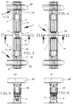
- the lock boxes 1 in the figures have a console 1 ', which is basically a welded construction can be made of joined sheets, beams, Web plates and belts.
- Guides 2 are provided, which extend over the entire length the console 1 'or over partial areas of this, as in FIGS. 1 and 2, the total length of the console 1 'results from the width of the press.
- the slides 3, 4 are assigned to a gripper rail 23; the Carriages 5, 6 are assigned to a second gripper rail 23.
- the gripper rails 23 wear holding means for the sheet metal parts in a known manner and are in the transport direction the workpieces, arrow 28 in Fig. 2, as necessary towards each other and from each other away in the closing / opening movement and in the vertical direction for lifting and lowering move.
- Spindles 7, 8 are in the lock boxes 1 and the console 1 'of FIGS. 1 to 6 rotatably mounted, which is parallel to the longitudinal extension of console 1 'and whose guides extend 2.
- the spindles 7, 8 in Figures 1, 2, 3 and 5 point right-handed threads and are each via a toothed belt drive 11 or 12 of console-fixed motors 9 or 10 rotary drives.
- the sledges 3, 4, 5, 6 are connected to the spindles by means of spindle nuts 25.
- the carriages 3 and 6 each have a pressure cylinder 24.
- the carriage 3 is provided with a bearing block 13 in which a plate or double plate 19 or a pair of plates or a pair of double plates 19, 19 'is pivotally mounted.
- the carriage 6 has the same design with the ones in the bearing block 16 or the bearing blocks 16, 16 'brackets 19, 19'.
- the carriage 4 has bearing blocks 14 and 14 'in which parallel links 17, 18 and 17 '18' are pivotally mounted.
- the carriage 5 has the same design with the ones in the bearing blocks 15 and 15 ', the latter is not recognizable, mounted parallel core 17, 18, 17', 18 '.
- the tabs 19 or pairs of tabs 19, 19 'on the carriage 3 or 6 are with the carriage end region facing away from one of the parallel links 17, 18, 17 ', 18', respectively their half effective total length articulated.
- the parallel links 17, 17 '18, 18' are with the end regions remote from the slide on bearing blocks 22, 22 ′ of a carrier part 21 articulated.
- This carrier part serves directly as a guide or when in use additional equipment, such as separate storage, admission or support the gripper rail 23 or a portion of this with a divided gripper rail.
- the Pivots of the brackets and parallel links are generally positioned at 20.
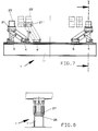
- FIGS. 7 and 8 show the use of the known linear motor principle shown.
- the secondary part is formed by structures 26 in the console 1 '; of the
- the primary part is formed by structures 27 in the respective carriages 3, 4, 5, 6 of the Figure 7.
- the application of the linear motor principle for the transfer of workpieces has been described in US-A-4,887,446 and in DE 195 06 079. Here the principle acts directly on the workpiece or on the holding means that grips it.
- the adjustment of the carriages 3 and 4 and the carriages 5 and 6 via the toothed belt drive 11, 12 towards the spindles 7, 8 towards and away from each other causes the gripper rail 23 guided and supported on the supports 21 to be raised or lowered the lifting-lowering movement is an absolutely vertical movement if only the carriages 4 and 5 are moved, the carriages 3 and 6 are held. Furthermore, the movement of the gripper rails 23 towards and away from one another can be achieved by adjusting the carriages 3, 4 and 5, 6 together.
Landscapes
- Engineering & Computer Science (AREA)
- Mechanical Engineering (AREA)
- Press Drives And Press Lines (AREA)
- Reciprocating Conveyors (AREA)
Abstract
Description
- Fig. 1
- einen Schließkasten einer Presse mit Einrichtungen nach der Erfindung,
- Fig. 2
- den in Fig. 1 gezeigten Schließkasten in Perspektive.
- Fig. 3
- eine Draufsicht auf den in Fig. 1 gezeigten Schließkasten,
- Fig. 4
- eine Draufsicht auf einen Schließkasten einer weiteren, hinsichtlich der Antriebsmittel geänderten Ausführung,
- Fig. 5
- eine Draufsicht auf Antriebsmittel nach den Fign. 1, 2 und 3, gemäß Schnitt II-II in Fig. 3,
- Fig. 6
- eine Draufsicht auf Antriebsmittel gemäß Schnitt III-III in Fig. 4,
- Fig. 7
- einen Schließkasten mit Einrichtungen nach der Erfindung in weiterer Antriebsausgestaltung und
- Fig. 8
- einen Schnitt gemäß dem Schnittverlauf I-I in Fig. 7.
Desweiteren ist die Bewegung der Greiferschienen 23 aufeinander zu und voneinander weg durch gemeinsame Verstellung der Schlitten 3, 4 bzw. 5, 6 erreichbar.
Claims (4)
- Presse, Mehrstufenpresse, Großteilstufenpresse o.dgl. Pressenanlage, mit einer Umsetzeinrichtung für Werkstücke durch die Bearbeitungsstufen, mit Antriebsmitteln und Führungsmitteln für eine Greiferschiene (23) bzw. für jede von zwei Greiferschienen (23) in den Bewegungsachsen Umsetzen, Heben-/Senken und ggf. Öffnen-/Schließen, gekennzeichnet durch zwei Schlitten (3, 4, 5, 6) einer ersten und einer zweiten Art, die einer Greiferschiene (23) bzw. je einer Greiferschiene (23) bei Verwendung von zwei Greiferschienen (23) zugeordnet sind und die Schlitten (3, 4, 5, 6) aufeinander zu und voneinander weg, quer zur eigentlichen Umsetzrichtung (28) der Werkstücke unabhängig voneinander antreibbar sind, daß an einem Schlitten der ersten Art (4, 5) zwei Parallellenker (17, 17', 18, 18') drehbar gelagert sind, die anderenends drehbar an einem Trägerteil (21) für eine Greiferschiene (23) gelagert sind und an dem anderen Schlitten (3, 6) der zweiten Art eine Lasche (19, 19') drehbar gelagert ist, die anderenends auf halber Länge an einem der Parallellenker (17, 17', 18, 18') angreift und hier drehbar gelagert ist, wobei die Länge der Lasche (19, 19') der halben Länge des Parallellenkers (17, 17') entspricht, bezogen auf die Abstände deren Drehpunkte (20), und wobei das Trägerteil (21) direkt als Längsführung für eine Greiferschiene (23), bei Verwendung separater Führungsmittel indirekt der Lagerung der Geiferschiene (23) dient.
- Presse nach Anspruch 1, dadurch gekennzeichnet, daß zwei Trägerteile (21) für die Aufnahme je einer Greiferschiene (23) je Schließkasten (1) vorhanden sind und die Schlitten (3, 4, 5, 6) von gemeinsamen, über im wesentlichen die Länge der Öffnen-Schließen-Bewegung ausführenden Schlitten (3, 4, 5, 6) geführten, motoriell getriebenen Spindeln (7, 8) beaufschlagbar sind.
- Presse nach Anspruch 1, dadurch gekennzeichnet, daß die Schlitten (3, 4, 5, 6) nach dem Linear-Motor-Prinzip angetrieben sind.
- Presse nach Anspruch 3, gekennzeichnet durch ein sich im wesentlichen über die Länge der Öffnen-Schließen-Bewegung erstreckenden Sekundärteil (26) und in die Schlitten (3, 4, 5, 6) integrierte Primärteile.
Applications Claiming Priority (2)
| Application Number | Priority Date | Filing Date | Title |
|---|---|---|---|
| DE19721613A DE19721613A1 (de) | 1997-05-23 | 1997-05-23 | Presse mit einer Umsetzeinrichtung für Werkstücke |
| DE19721613 | 1997-05-23 |
Publications (2)
| Publication Number | Publication Date |
|---|---|
| EP0879660A2 true EP0879660A2 (de) | 1998-11-25 |
| EP0879660A3 EP0879660A3 (de) | 2002-01-16 |
Family
ID=7830286
Family Applications (1)
| Application Number | Title | Priority Date | Filing Date |
|---|---|---|---|
| EP98108951A Withdrawn EP0879660A3 (de) | 1997-05-23 | 1998-05-16 | Presse mit einer Umsetzeinrichtung für Werkstücke |
Country Status (3)
| Country | Link |
|---|---|
| US (1) | US6073551A (de) |
| EP (1) | EP0879660A3 (de) |
| DE (1) | DE19721613A1 (de) |
Cited By (3)
| Publication number | Priority date | Publication date | Assignee | Title |
|---|---|---|---|---|
| EP1112806A3 (de) * | 1999-12-27 | 2006-05-03 | GROB-Werke Dr. h.c. mult. Dipl.-Ing. Burkhart Grob e.K. | Werkzeugmaschine mit einer in mindestens einer Arbeitsebene bewegbaren und positionierbaren Werkzeugspindel |
| CN104226840A (zh) * | 2013-06-19 | 2014-12-24 | 坤霖精密有限公司 | 自动送料机的一体式传动机构 |
| CN108032127A (zh) * | 2017-12-13 | 2018-05-15 | 吴龙世 | 自动上料机械手 |
Families Citing this family (16)
| Publication number | Priority date | Publication date | Assignee | Title |
|---|---|---|---|---|
| DE19841621A1 (de) * | 1998-09-11 | 2000-03-16 | Schuler Pressen Gmbh & Co | Transfereinrichtung mit Ausfallschutz |
| DE10023241C2 (de) | 2000-05-12 | 2003-08-07 | Hermann Hagel | Transfereinrichtung und Verfahren zur Steuer einer Transfereinrichtung |
| DE10310941B4 (de) * | 2003-03-13 | 2005-06-02 | Fraunhofer-Gesellschaft zur Förderung der angewandten Forschung e.V. | Einrichtung zum Transport von Werkstücken |
| DE112010002838T5 (de) | 2009-07-06 | 2012-06-06 | Komatsu Ltd. | Werküberführungsvorrichtung für Pressmaschine undWerküberführungsanlage |
| JP5330182B2 (ja) * | 2009-10-05 | 2013-10-30 | アイダエンジニアリング株式会社 | ワーク搬送装置 |
| US8973768B1 (en) * | 2009-10-09 | 2015-03-10 | Par Systems, Inc. | Gantry robot system |
| US8333101B2 (en) | 2010-08-27 | 2012-12-18 | Honda Motor Co., Ltd. | Shiftable transfer apparatus for transferring workpiece to press |
| CN102358523A (zh) * | 2011-10-21 | 2012-02-22 | 中冶南方工程技术有限公司 | 带钢废料输出装置 |
| US8925363B2 (en) | 2012-10-17 | 2015-01-06 | Toyota Motor Engineering & Manufacturing North America, Inc. | Split idle station assemblies for transfer press assemblies |
| JP5792352B1 (ja) * | 2014-06-04 | 2015-10-07 | Dmg森精機株式会社 | ワーク昇降装置 |
| JP6671119B2 (ja) * | 2015-07-31 | 2020-03-25 | コマツ産機株式会社 | ワーク搬送装置 |
| JP6192131B2 (ja) * | 2015-12-10 | 2017-09-06 | アイダエンジニアリング株式会社 | プレス機械のワーク搬送装置 |
| CN109014078B (zh) * | 2018-09-12 | 2019-12-03 | 浙江中杭水泵股份有限公司 | 一种工厂用造型机 |
| CN111717637A (zh) * | 2020-06-08 | 2020-09-29 | 青岛黄海学院 | 一种机械加工自动上料装置 |
| JP7489856B2 (ja) * | 2020-08-06 | 2024-05-24 | コマツ産機株式会社 | ワーク搬送装置 |
| CN121289385B (zh) * | 2025-12-03 | 2026-07-03 | 南京信方达高端装备有限公司 | 一种金属锻压模具及成型机床 |
Family Cites Families (11)
| Publication number | Priority date | Publication date | Assignee | Title |
|---|---|---|---|---|
| US3010587A (en) * | 1957-09-20 | 1961-11-28 | Richard G Hollinger | Workpiece transfer mechanism |
| JPS59143535U (ja) * | 1983-03-14 | 1984-09-26 | 株式会社小松製作所 | トランスフアプレスにおけるアイドルステ−シヨン用のフインガ装置 |
| JPS59197325A (ja) * | 1983-04-22 | 1984-11-08 | Aida Eng Ltd | フィードバの駆動装置 |
| DE3702962A1 (de) * | 1987-01-31 | 1988-08-11 | Bayer Ag | Schaedlingsbekaempfungsmittel auf pyrimidin-derivat basis |
| BR8701734A (pt) * | 1987-03-24 | 1987-08-11 | Prodty Engenharia E Comercio L | Aperfeicoamento em sistema de transferencia de pecas, com mecanismo de levantamento das pecas,ou terceiro eixo,derivado do acionamento do eixo de aproximacao das garras |
| US4887446A (en) * | 1988-06-23 | 1989-12-19 | Maher John H | System for transferring workpieces through a series of work stations |
| SE9004006L (sv) * | 1990-12-14 | 1992-01-20 | Volvo Ab | Anordning foer oeverfoering av arbetsstycken fraan en maskin till en annan, foeretraedesvis pressar |
| DE4331479A1 (de) * | 1993-09-16 | 1995-03-23 | Guenter Zierpka | Vorschubeinrichtung zum schrittweisen Material- und/oder Werkstücktransport an bzw. in intermittierend arbeitenden Produktionsmaschinen |
| DE19506079A1 (de) * | 1995-02-22 | 1996-08-29 | Schuler Pressen Gmbh & Co | Vorrichtung zum Transfer von Werkstücken durch eine Folge von Bearbeitungsstationen |
| DE19526490A1 (de) * | 1995-07-20 | 1997-01-23 | Schuler Pressen Gmbh & Co | Transferanlage mit Dreiachsentransfer |
| JP3117118B2 (ja) * | 1995-07-31 | 2000-12-11 | ヒーハイスト精工株式会社 | 多自由度位置決め機構 |
-
1997
- 1997-05-23 DE DE19721613A patent/DE19721613A1/de not_active Withdrawn
-
1998
- 1998-05-16 EP EP98108951A patent/EP0879660A3/de not_active Withdrawn
- 1998-05-26 US US09/083,977 patent/US6073551A/en not_active Expired - Fee Related
Cited By (4)
| Publication number | Priority date | Publication date | Assignee | Title |
|---|---|---|---|---|
| EP1112806A3 (de) * | 1999-12-27 | 2006-05-03 | GROB-Werke Dr. h.c. mult. Dipl.-Ing. Burkhart Grob e.K. | Werkzeugmaschine mit einer in mindestens einer Arbeitsebene bewegbaren und positionierbaren Werkzeugspindel |
| CN104226840A (zh) * | 2013-06-19 | 2014-12-24 | 坤霖精密有限公司 | 自动送料机的一体式传动机构 |
| CN104226840B (zh) * | 2013-06-19 | 2016-03-30 | 坤霖精密有限公司 | 自动送料机的一体式传动机构 |
| CN108032127A (zh) * | 2017-12-13 | 2018-05-15 | 吴龙世 | 自动上料机械手 |
Also Published As
| Publication number | Publication date |
|---|---|
| EP0879660A3 (de) | 2002-01-16 |
| US6073551A (en) | 2000-06-13 |
| DE19721613A1 (de) | 1998-11-26 |
Similar Documents
| Publication | Publication Date | Title |
|---|---|---|
| DE19721613A1 (de) | Presse mit einer Umsetzeinrichtung für Werkstücke | |
| EP0672480B1 (de) | Transportsystem | |
| EP0671228B1 (de) | Transporteinrichtung für Werkstücke in einer Presse | |
| DE19654475A1 (de) | Transfereinrichtung und Mehrstationenpresse | |
| DE3881009T2 (de) | Pressentransfervorrichtung. | |
| DE10328447B4 (de) | Transferpresse mit verbesserter Raumausnutzung | |
| EP0901848B1 (de) | Transferpressen mit automatischem Toolingwechsel | |
| EP0647488A1 (de) | Presse, Mehrstufenpresse od. dgl. Umformmaschine | |
| DE1602602B2 (de) | Zufuehrtisch zur laengs- und querbewegung plattenfoermiger werkstuecke an einer stanzpresse | |
| DE69129077T2 (de) | Verfahren und vorrichtung zum schneiden von rohren, in welchem die rohre mittels einer rotierenden festhaltplatte in schneidposition gebracht werden | |
| EP1000680B1 (de) | Modulare Transfereinrichtung mit Schwenk- und Linearantrieben | |
| DE202020101753U1 (de) | Wechselvorrichtung für einen Wechsel von wenigstens zwei Werkstückauflagen für eine Bearbeitungsmaschine | |
| DE4310057A1 (de) | Vorrichtung zum Transfer von Werkstücken durch eine Folge von Bearbeitungsstationen | |
| EP0701872A1 (de) | Einrichtung zum dreidimensionalen Antrieb von Greiferschienen | |
| EP0507098A1 (de) | Transporteinrichtung zum Transportieren von grossflächigen Teilen in einer Stufenpresse | |
| DE69703978T2 (de) | Vorrichtung zum regeln der grösse eines werkzeugmaschinen-blechhalters | |
| EP0597386B1 (de) | Einrichtung zum Umsetzen von Blechteilen in einer Pressenanlage | |
| DE4320430C2 (de) | Transferpressenkomplex | |
| EP1402968A1 (de) | Boerdelvorrichtung | |
| EP0650781A2 (de) | Antriebseinrichtung für einen mehrachsigen Transport von Werkstücken in einer Transferpresse | |
| DE4013334A1 (de) | Greiferschienenantrieb fuer transferpressen | |
| DE2365980C2 (de) | Vorschubeinrichtung zum schrittweisen Material- und/oder Werkstücktransport, insbesondere in Pressen | |
| DE3229943A1 (de) | Transporteinrichtung fuer stufenpressen oder pressenstrassen | |
| DE4132221C2 (de) | Greiferschienen-Transfereinrichtung einer mehrstufigen Presse | |
| DD278963A1 (de) | Greiferleistenwechseleinrichtung fuer den automatischen werkzeugwechsel an pressen |
Legal Events
| Date | Code | Title | Description |
|---|---|---|---|
| PUAI | Public reference made under article 153(3) epc to a published international application that has entered the european phase |
Free format text: ORIGINAL CODE: 0009012 |
|
| AK | Designated contracting states |
Kind code of ref document: A2 Designated state(s): AT BE CH CY DE DK ES FI FR GB GR IE IT LI LU MC NL PT SE Kind code of ref document: A2 Designated state(s): DE ES FR GB IT SE |
|
| AX | Request for extension of the european patent |
Free format text: AL;LT;LV;MK;RO;SI |
|
| RAP1 | Party data changed (applicant data changed or rights of an application transferred) |
Owner name: SCHULER PRESSEN GMBH & CO. KG |
|
| PUAL | Search report despatched |
Free format text: ORIGINAL CODE: 0009013 |
|
| AK | Designated contracting states |
Kind code of ref document: A3 Designated state(s): AT BE CH CY DE DK ES FI FR GB GR IE IT LI LU MC NL PT SE |
|
| AX | Request for extension of the european patent |
Free format text: AL;LT;LV;MK;RO;SI |
|
| 17P | Request for examination filed |
Effective date: 20020130 |
|
| AKX | Designation fees paid |
Free format text: DE ES FR GB IT SE |
|
| GRAP | Despatch of communication of intention to grant a patent |
Free format text: ORIGINAL CODE: EPIDOSNIGR1 |
|
| STAA | Information on the status of an ep patent application or granted ep patent |
Free format text: STATUS: THE APPLICATION IS DEEMED TO BE WITHDRAWN |
|
| 18D | Application deemed to be withdrawn |
Effective date: 20040121 |