EP0880005A2 - Treibladung für eine Munitionskartusche und Herstellungsverfahren dafür - Google Patents
Treibladung für eine Munitionskartusche und Herstellungsverfahren dafür Download PDFInfo
- Publication number
- EP0880005A2 EP0880005A2 EP98107204A EP98107204A EP0880005A2 EP 0880005 A2 EP0880005 A2 EP 0880005A2 EP 98107204 A EP98107204 A EP 98107204A EP 98107204 A EP98107204 A EP 98107204A EP 0880005 A2 EP0880005 A2 EP 0880005A2
- Authority
- EP
- European Patent Office
- Prior art keywords
- stick
- projectile
- propellant
- cartridge
- sticks
- Prior art date
- Legal status (The legal status is an assumption and is not a legal conclusion. Google has not performed a legal analysis and makes no representation as to the accuracy of the status listed.)
- Withdrawn
Links
- 239000003380 propellant Substances 0.000 title claims abstract description 114
- 238000004519 manufacturing process Methods 0.000 title description 3
- 238000011068 loading method Methods 0.000 claims abstract description 33
- 238000000034 method Methods 0.000 claims description 20
- 239000000463 material Substances 0.000 claims description 11
- 230000002093 peripheral effect Effects 0.000 claims description 10
- 239000011800 void material Substances 0.000 claims description 6
- 230000002452 interceptive effect Effects 0.000 claims 2
- 238000012856 packing Methods 0.000 abstract description 6
- 230000008569 process Effects 0.000 description 6
- 229910001369 Brass Inorganic materials 0.000 description 4
- 239000010951 brass Substances 0.000 description 4
- 238000001125 extrusion Methods 0.000 description 4
- 238000010304 firing Methods 0.000 description 4
- 230000006872 improvement Effects 0.000 description 4
- 239000000020 Nitrocellulose Substances 0.000 description 3
- 229910000831 Steel Inorganic materials 0.000 description 3
- 229920001220 nitrocellulos Polymers 0.000 description 3
- 230000000087 stabilizing effect Effects 0.000 description 3
- 239000010959 steel Substances 0.000 description 3
- 230000008901 benefit Effects 0.000 description 2
- 239000000567 combustion gas Substances 0.000 description 2
- 238000005520 cutting process Methods 0.000 description 2
- 238000013461 design Methods 0.000 description 2
- 238000001514 detection method Methods 0.000 description 2
- 230000000694 effects Effects 0.000 description 2
- 239000012634 fragment Substances 0.000 description 2
- 239000007789 gas Substances 0.000 description 2
- 238000003801 milling Methods 0.000 description 2
- 230000000750 progressive effect Effects 0.000 description 2
- 238000013022 venting Methods 0.000 description 2
- XLYOFNOQVPJJNP-UHFFFAOYSA-N water Substances O XLYOFNOQVPJJNP-UHFFFAOYSA-N 0.000 description 2
- 230000002411 adverse Effects 0.000 description 1
- UQMRAFJOBWOFNS-UHFFFAOYSA-N butyl 2-(2,4-dichlorophenoxy)acetate Chemical compound CCCCOC(=O)COC1=CC=C(Cl)C=C1Cl UQMRAFJOBWOFNS-UHFFFAOYSA-N 0.000 description 1
- 238000006243 chemical reaction Methods 0.000 description 1
- 238000010276 construction Methods 0.000 description 1
- 238000011161 development Methods 0.000 description 1
- 230000018109 developmental process Effects 0.000 description 1
- 238000005516 engineering process Methods 0.000 description 1
- 230000001747 exhibiting effect Effects 0.000 description 1
- 238000003780 insertion Methods 0.000 description 1
- 230000037431 insertion Effects 0.000 description 1
- 239000007788 liquid Substances 0.000 description 1
- 230000005055 memory storage Effects 0.000 description 1
- 238000002156 mixing Methods 0.000 description 1
- 238000012986 modification Methods 0.000 description 1
- 230000004048 modification Effects 0.000 description 1
- 238000011017 operating method Methods 0.000 description 1
- 238000004806 packaging method and process Methods 0.000 description 1
- 238000002360 preparation method Methods 0.000 description 1
- 230000009467 reduction Effects 0.000 description 1
- 230000035945 sensitivity Effects 0.000 description 1
- 238000007493 shaping process Methods 0.000 description 1
- 239000004449 solid propellant Substances 0.000 description 1
- 238000012546 transfer Methods 0.000 description 1
Images


Classifications
-
- F—MECHANICAL ENGINEERING; LIGHTING; HEATING; WEAPONS; BLASTING
- F42—AMMUNITION; BLASTING
- F42B—EXPLOSIVE CHARGES, e.g. FOR BLASTING, FIREWORKS, AMMUNITION
- F42B5/00—Cartridge ammunition, e.g. separately-loaded propellant charges
- F42B5/02—Cartridges, i.e. cases with charge and missile
- F42B5/18—Caseless ammunition; Cartridges having combustible cases
- F42B5/181—Caseless ammunition; Cartridges having combustible cases consisting of a combustible casing wall and a metal base; Connectors therefor
-
- F—MECHANICAL ENGINEERING; LIGHTING; HEATING; WEAPONS; BLASTING
- F42—AMMUNITION; BLASTING
- F42B—EXPLOSIVE CHARGES, e.g. FOR BLASTING, FIREWORKS, AMMUNITION
- F42B5/00—Cartridge ammunition, e.g. separately-loaded propellant charges
- F42B5/02—Cartridges, i.e. cases with charge and missile
- F42B5/16—Cartridges, i.e. cases with charge and missile characterised by composition or physical dimensions or form of propellant charge, with or without projectile, or powder
Definitions
- the present invention is directed generally to the field of sophisticated, high velocity, large or medium caliber projectile ammunition and, more particularly, to an improved geometric propellant loading configuration for such ammunition.
- the propellant system of the invention includes several mutually contiguous extrudable stick shapes that in concert result in highly efficient use of propellant load space.
- the system reduces loading, assembling and packing (LAP) labor and overall cost, yet provides a dense pattern to increase propellant load and high perforation to improve burning progressivity over prior stick loads and more reliable and improved ballistic performance.
- Conventional ammunition of the class described such as that fired by military tank cannons, are typically breech loaded and electrically activated and fired from within the tank.
- the projectiles typically are fired electrically using a primer circuit to ignite a primer which, in turn, ignites a main propellant charge by DC voltage from a thermal battery activated by the primer.
- the projectile may contain electronics activated when firing occurs and which utilize memory storage to operate a preprogrammed target acquisition or proximity system and the arming and detonating devices in the shell during the flight of the shell. Then, it is apparent that large caliber ammunition, with respect to target acquisition, proximity detection, arming and detonating, has become very sophisticated.
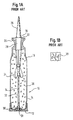
- Figure 1 depicts a typical large caliber round, which may be fired from the main turret cannon of a tank or other artillery piece, loaded with propellant of one prior art type.
- the round is shown generally at 10 at Figure 1 and includes a base plate section 12 connected with the wall of a cartridge casing and having a generally cylindrical portion 14 and a necked down or tapered upper portion 16. Except for the base plate 12, the shell or cartridge sidewall 14 itself is normally made of a combustible material such as molded nitrocellulose or other such material itself consumed during the firing of the shell.
- a projectile is shown at 18 with discarding sabot members 20 and 22 which peel away and drop off just after the projectile is discharged from the muzzle of the cannon.
- a plurality of stabilizing guidance fins (normally six in number) as at 24 are also provided.
- the nose cone section 26 may contain an electronics package and the warhead section 28 may contain arming and detonating circuitry.
- a primer housing shown generally at 30 contains a conductive ignition electrode or primer button (not shown) and stub base 31.
- the primer housing and stub base are connected with a generally hollow brass or other type metal center-core primer tube 32 which has a plurality of openings as at 34 which access and address the general propellant charge volume 36.
- the propellant illustrated consists of closely packed, generally uniformly shaped, perforated, granular solid propellant grains 38 ( Figure 1B) perhaps 2 to 3 cm long by about 0.5 cm in diameter.
- the shell is normally fired electrically using direct current to ignite the primer in the primer housing and through the primer tube 32, thereby igniting the main propellant 38 via the openings 34.
- the propellant during the burn, generate gases at an ever increasing rate as the projectile advances along the barrel. Accordingly, a configuration of propellant which creates predictably and ever increasing burn surface area as the burn progresses is very desirable.
- the present standard is based on the performance of stick propellant, particularly the round extruded stick shape which has increased shell velocities over earlier propellant loadings.
- stick propellant particularly the round extruded stick shape which has increased shell velocities over earlier propellant loadings.
- a great many relatively small diameter sticks must be used, and the stick propellant has also presented difficulties with respect to achieving high loading density ( Figures 2A, 2B, 3).
- the loading process for a cartridge using stick propellant is also very labor intensive and performance is not optimum because adjacent surfaces of the sticks do not match, as in the case of random placement with granular propellant.
- the method used to extrude both stick and granular propellant includes pins that create perforations during the process. With sticks of present size (below), this method may create perforation and web inconsistencies which actually reduce the propellant performance.
- Figures 2A and 2B are partial sectional views to illustrate prior art loading geometries for propellant sticks for a 120-MM shell 40 including a projectile 42 with six stabilizing guidance fins 44.
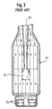
- Figure 3 is a further schematic drawing that illustrates a vertical crossection of a fragment of a similar shell 50 without the baseplate containing projectile 52 with fins 54 and an ignition system as shown at 56.
- the loading of the cartridge 50 as can be seen from Figure 3 requires at least eight different sizes or lengths of stick propellant (A-H) and in large quantities. Loading is by necessity labor intensive.
- Another object of the invention is to produce a propellant geometric configuration that uses fewer, larger grain shapes.
- a further object of the invention is to provide a dense propellant loading geometry that enables convenient and efficient assembly of propellant within a straight or necked-down cartridge.
- Yet another object of the invention is to provide a method of loading a propellant which uses a highly accurate, repeatable geometric shapes capable of sustaining high perforation density.
- the present invention solves many of the prior art problems associated with large caliber munition propellant cartridge loading by the provision of propellant segments in the form of a reduced number of larger distinct mutually contiguous propellant stick shapes that yield more efficient use of propellant load space.
- the size and geometric configuration of the sticks yields exceptional uniformity of stick outer webs to allow very close packing of propellant sticks or grains and further enable large numbers of perforations per propellant grain to thereby achieve improved highly progressive burning and enhanced interior ballistic performance.
- the propellant load of the invention then exceeds the superior burning performance qualities of previous stick propellant loads at a reduced cost to produce because cartridge loading, assembly, packing (LAP) is made easier and safer.
- the total available propellant load can be increased by about 12 to 18 percent over a typical prior art in a conventional stick load for the same shell depending on whether round or hexagonal crossectional sticks are used
- the geometric configuration described by the stick shapes of the present invention can be accomplished using but four different extrusion dies.
- the preferred configuration includes two isosceles triangle stick or perforated pie propellant shapes (one of which is made trapezoidal to fit about a typical high intrusion projectile) a regular polygon shape and a modified parallelogram shape.
- the isosceles triangles and trapezoids are typically equilateral (60° ) or modified equilateral triangles in the case of a projectile having a six-bladed fin to form a regular outer hexagonal shape about the projectile and a regular hexagonal annulus inside an outer peripheral row of sticks in the cartridge. These shapes can be produced with a reduced or minimized amount of skiving or milling of contour surfaces to conform the sticks to the cartridge case base and propellant fin/boom assembly.
- Each of the propellant sticks contains opposed partial/cuts or kerfs perpendicular to and connected with the longitudinal perforations formed upon extrusion to vent the perforations at regular short intervals to avoid occurrence of choked flow of combustion gases within the perforations and to maintain the extraordinary progressivity per grain associated with the numerous perforations per grain.
- the unique 60° or perforated pie geometric configuration enables convenient high density stick propellant charge loading within necked-down steel and brass cartridge cases, as well as with combustible or nitrocellulose cartridge cases. Accordingly, it will be recognized that in addition to the simultaneous minimization of wasted void volumes due to interstitial/chord spaces and increase in grain progressivity or the rate in which the controlled burn increases gas volume output, an important aspect of the invention is the ease of loading, assembling, packaging (LAP) of the munition round. This is accomplished by initial insertion of the ordered outer row of skived and kerfed sticks into the cartridge case and positioning them against the periphery of the cartridge case wall.
- LAP ease of loading, assembling, packaging
- the inclusion of the 60° equilateral triangle or pie shapes in the outer wall enables the creation of a stable hexagonal geometric annular recess centered to the configuration about the periphery of the cartridge.
- skived and kerfed sticks are assembled into a projectile stick bundle around the projectile fins/boom, together with a single hexagonal stick within the center of the projectile stick bundle placed beneath the fin section within the center of the stick bundle so that it buts against the fin hub.
- This bundle is taped together tightly at both ends to yield a hexagonal geometric projectile stick bundle which is then easily, readily assembled into the hexagonal annular stick recess configuration to yield the completed propellant system load.
- the geometric grain design of the stick loading configuration of the present invention can be adapted to any size of large caliber cartridge including 60-MM, 105-MM, 120-MM and 140-MM involving projections with 6-bladed fins.
- the conventional round or hexagonal grains or sticks do not permit the assembly of a stable outer peripheral row of skived and kerfed sticks into which the remainder can be assembled.
- This improvement is significant because the configuration of the invention facilitates the assembly of the propellant into conventional "necked down" brass or steel cartridge cases (e.g., the 105-MM conventional cartridge case) inasmuch as the outer row covers the top diameter reduction.
- the loading configuration or system of the invention can be used with any conventional extrudable and otherwise processsable in new conventional stick propellant. These are made in a well-known manner normally from carpet rolled propellant which is dried, aged, pre-cut for extrusion and extruded with the desired perforation pattern, cut to length and kerf cut prior to assembly. Conventional propellant materials such as JA2 or other materials. The shapes are preferably fabricated from blended and rolled shaped propellant stock or from extruded bar stock. The fabrication process can be tailored to meet the requirements of the individual cartridge and performance requirements for maximum load, propellant load density and ballistic performance.
- each stick shape is typically fabricated using a die set and press or a water jet cutter or sawing process compatible with the propellant material and designed to more closely match the cartridge casing inside diameter or the geometry of the projectile.
- the water jet system can be programmed to process the propellant pieces for a full round in order and scrap propellant is typically recycled and reused. Additional details concerned with the preparation of the propellant are illustrated and described in the above-cross referenced co-pending application.
- substantially higher propellant loading density is achieved in large caliber ammunition cartridges without sacrificing burning progression performance.
- the propellant of the present invention not only enables a denser packing of the cartridge in respect to previous stick-type loads, it reduces the number of sticks required and greatly reduces the cost of loading-assembling-packing (LAP), increasing the ease and safety of assembly into the cartridge.
- the embodiment of the detailed description illustrates the propellant system of the invention as used in a 120-MM KE cartridge in which the projectile has a symmetrical six-bladed fin. It should be understood that, in this regard, the propellant system can be modified for use with other rounds including those using projectiles having a different number of fins, the detailed embodiment being illustrative and not intended to be limiting with respect to the invention.
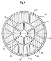
- Figure 4 depicts a sectional view through a typical 120-MM KE cartridge illustrating a propellant geometry arrangement in accordance with the invention.
- the configuration includes a cartridge casing 100, which may be fabricated of nitrocellulose or other combustible material and includes a kinetic energy projectile 102 having six symmetrically disposed radially extending fin blades 104 carried within the cartridge shell 100.
- An inner ring including a plurality of elongate trapezoidal shaped core stick segments 106 which extend along and between the six symmetrical fin blades 104 are provided which with the projectile 102 present a hexagonal peripheral projectile stick bundle shape.
- An outer ring of elongated shaped stick segments is provided including equilateral triangle segments 108 and generally quadrilateral shaped stick segments 110 which, when disposed is illustrated in Figure 4, provide an outer ring of propellant sticks which substantially occupies the available propellant volume in the cartridge case outside the projectile stick bundle.
- the outer ring forms a stable interior annulus generally shaped to just accommodate the peripheral projectile stick bundle geometry and an outer geometry generally following the casing interior without requiring a great deal of special shaping, i.e., shiving or milling.
- the inner and outer stick rings require but three different geometric shapes of elongated stick segments.
- the configuration of the outer ring of the equilateral triangle and modified quadrilateral shapes forms of itself a stable annulus about the periphery of the cartridge 100 such that after assembly of the outer ring, the projectile stick bundle or core segment including the projectile 102 and the trapezoidal segments 106 can be inserted as a unit within the outer ring to complete the loading.
- a further hexagonal segment, illustrated in Figures 5C and 7A at 114, is utilized as a central stick in the projectile bundle beneath the aft end of the projectile to complete the projectile bundle. As can be seen in Figure 7A, this stick is considerably shorter than the sticks 106, 108 and 110.
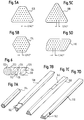
- Figures 5A-5D illustrate the four basic propellant stick shapes of the invention, particularly with respect to the perforation (perf) patterns employed.
- the typical center-to-center distance is approximately 0.14 in. (3.56 MM) and the typical perforation diameter is 0.030 in. (0.762 MM) which results in an average internal web thickness equal to about 0.11 in. (2.79 MM).
- a relatively uniform outer peripheral web thickness equal to approximately one half of the internal web thickness is provided.
- the trapezoidal shapes 106 are typically 42 perf; the equilateral triangle shapes 108, 45 perf; and the modified quadrilateral shapes 110 typically 43 perf.
- the shorter hexagonal sections are typically 37 perf, as illustrated.
- Figure 6 depicts a schematic representation of a preferred method of kerf cutting shapes including the shapes used for the propellant load of the present invention.
- stick 120 having a pattern series of longitudinal perforations 122 is subjected to a plurality of oppositely administered partial kerf cuts at regular intervals as illustrated at 124, 126, 128 and 130.
- each pair of partial kerf cuts overlaps as at 132 and 134 to insure that all of the perforations 122 are intersected by the partial cuts or kerfs.
- the partial cuts or kerfs must be spaced at uniform intervals along the length of the stick at a spacing sufficiently short to provide adequate venting so as to avoid occurrence of choked flow combustion gases within the perforations.
- FIGS 7A-7D further illustrate relative full length perspective views of the propellant grain geometry for each of the individual stick propellant grains.
- the triangular stick 108 in Figure 7B and modified quadrilateral stick 110 in Figure 7D are notched at the lower end to accommodate constrictions in the lower cartridge case at 140 and 142 respectively.
- the upper portion of a typical trapezoidal shape 106 exhibits skived/milled contour internal surfaces to permit the stick to conform to the projectile fin/boom assembly at 144.
- Figures 8, 9 and 10 further illustrate three views which correspond to illustrating the interlocking components of a typical large caliber kinetic energy cartridge such as the 120-MM round.
- Figure 8 is a perspective view, with parts cut away illustrating a typical large caliber, possibly 120-MM combustible cartridge case for use with the propellant system of the present invention.
- the case is shown generally at 150 and includes a combustible sidewall 152 having a tapered nose at 154 and including a baseplate 156 which is equipped with a base ignition system including a stub base primer 158, a conventional center-core type primer as shown in Figure 1 is unnecessary with the loading configuration of the present invention.
- Figure 10 is a perspective view, with parts cut away, illustrating the interlocked stick propellant grains of the invention illustrated in the crossectional view of Figure 4 arranged so as to fit in the cartridge case of Figure 8, but without the presence of the kinetic energy projectile shown generally at 160 in the fragmentary perspective view of Figure 9.
- the projectile including a central body or boom 162, a 6-bladed fin system 164 and a discarding Sabot system part of which is illustrated at 166 and which mounts in the corresponding area of the cartridge shell 150 with the boom and fin nesting in the correspondingly shaped propellant grains as partially illustrated in the perspective view of Figure 10.
- the outer peripheral ring which includes triangular shapes 108 sandwiched between oppositely disposed pairs of modified quadrilateral sticks 110 itself forms a stable ring about the periphery of the shell 100 or 150, such that this outer ring can be readily assembled utilizing a final equilateral triangular stick 108 as the key to completing the circular arch.
- this outer annulus yields a stable hexagonal recess within the cartridge of a diameter less than or equal to that of the necked-down portion of the cartridge illustrated at 154 in Figure 8. This readily accommodates the combination of the inner ring of six trapezoidal sticks 106 in combination with the kinetic energy projectile and the central lower stick 114.
- skived and kerfed sticks can be assembled into the cartridge case and positioned against the cartridge case wall and keyed into a stable annular stick configuration. Thereafter, the skived and kerfed sticks designated around the projectile fin/boom can be assembled together with the aft single hexagonal stick being placed within the center of the stick bundle so that it butts against the fin hub.
- This bundle may be taped tightly together at both ends forming a tight hexagonal stick bundle which can thereafter be readily inserted as a unit into the central void or recess space central to the outer row assembled about the periphery of a cartridge case wall thereby easily completing the propellant loading of the cartridge.
- the projectile stick bundle, including the hexagonal stick readily fits through the narrow portion of the necked-down cartridge as at 154.
- the configuration of the invention enables very high loading density (e.g., in excess of 1.0 kg/liter) of propellant within a cartridge and the relatively high perforation density allowed in the larger geometric shaped grains produces extraordinary progressivity per grain due to the numerous, closely spaced perforations per grain.
- the selected geometric shapes not only enable convenient and efficient assembly of the propellant (LAP) within a cartridge, but as seen in Figure 8 enable "base ignition” by the use of a stub primer eliminated the need for a "center-core type primer".
- the loading density and progressivity improvements directly contribute to enhance interior ballistic performance.
- the unique geometric configuration further allows the size of the grains to be changed while maintaining the relative geometry of the stick grains fixed so that by using appropriate dimensional scaling and optional addition/subtraction of perforation rows of each grain, the geometric design of the propellant configuration of the invention can be adapted to any size of large caliber cartridge, for example, 60-MM, 105-MM, 120-MM and 140-MM involving projectiles with 6-bladed fins.
- the system is compatible with any extrudable or otherwise conveniently processable stick propellant material exemplified by JA2 and has been found to increase the loading by 12 to 18 percent over conventional round or hexagonal stick grains.
- the ability to utilize a closely packed perforation pattern in the grains in combination with overlapping kerf cuts enables the reaction surface to increase at a tremendous rate during the burn, thereby imparting extraordinary progressivity to the burn.
- This progressivity improvement represents an important aspect of the improved propellant loading system of the invention, together with increase loading density and ease of assembly.
Landscapes
- Engineering & Computer Science (AREA)
- General Engineering & Computer Science (AREA)
- Containers And Packaging Bodies Having A Special Means To Remove Contents (AREA)
- Portable Nailing Machines And Staplers (AREA)
- Shaping Metal By Deep-Drawing, Or The Like (AREA)
Applications Claiming Priority (2)
| Application Number | Priority Date | Filing Date | Title |
|---|---|---|---|
| US841431 | 1977-10-12 | ||
| US08/841,431 US5892172A (en) | 1997-04-22 | 1997-04-22 | Propellant system |
Publications (2)
| Publication Number | Publication Date |
|---|---|
| EP0880005A2 true EP0880005A2 (de) | 1998-11-25 |
| EP0880005A3 EP0880005A3 (de) | 2002-02-13 |
Family
ID=25284875
Family Applications (1)
| Application Number | Title | Priority Date | Filing Date |
|---|---|---|---|
| EP98107204A Withdrawn EP0880005A3 (de) | 1997-04-22 | 1998-04-21 | Treibladung für eine Munitionskartusche und Herstellungsverfahren dafür |
Country Status (3)
| Country | Link |
|---|---|
| US (1) | US5892172A (de) |
| EP (1) | EP0880005A3 (de) |
| CA (1) | CA2233105C (de) |
Cited By (1)
| Publication number | Priority date | Publication date | Assignee | Title |
|---|---|---|---|---|
| EP2008053A4 (de) * | 2006-04-20 | 2012-10-17 | Eurenco Bofors Ab | Verfahren zur herstellung von treibmittelladungen für hochgeschwindigkeitsgeschosse, gemäss dem verfahren hergestellte treibmittelladungen und für das verfahren bestimmtes stabtreibmittel |
Families Citing this family (9)
| Publication number | Priority date | Publication date | Assignee | Title |
|---|---|---|---|---|
| US6167810B1 (en) * | 1998-12-04 | 2001-01-02 | United Defense, L.P. | Propelling material formed in strips for use in large caliber guns |
| US6378436B1 (en) * | 1999-02-22 | 2002-04-30 | Cordant Technologies Inc. | Portable propellant cutting assembly, and method of cutting propellant with assembly |
| US6195996B1 (en) | 1999-12-21 | 2001-03-06 | Trw Inc. | Body of gas generating material for a vehicle occupant restraint |
| US6502513B1 (en) * | 2000-11-17 | 2003-01-07 | Autoliv Asp, Inc. | Tablet form of gas generant |
| US20060054257A1 (en) * | 2003-04-11 | 2006-03-16 | Mendenhall Ivan V | Gas generant materials |
| US20050115439A1 (en) * | 2003-12-02 | 2005-06-02 | Abel Stephen G. | Multiple pulse segmented gas generator |
| US9188417B2 (en) | 2013-08-01 | 2015-11-17 | Raytheon Company | Separable sabot for launching payload |
| CN114382612A (zh) * | 2020-10-19 | 2022-04-22 | 内蒙古工业大学 | 一种高能易燃爆药柱填装装置 |
| DE102022131077A1 (de) * | 2022-11-24 | 2024-05-29 | Rheinmetall Waffe Munition Gmbh | Treibladung, Treibladungsanordnung und patronierte Munition |
Citations (1)
| Publication number | Priority date | Publication date | Assignee | Title |
|---|---|---|---|---|
| US5712445A (en) | 1993-05-04 | 1998-01-27 | Alliant Techsystems Inc. | Propellant system |
Family Cites Families (32)
| Publication number | Priority date | Publication date | Assignee | Title |
|---|---|---|---|---|
| FR437228A (fr) * | 1911-12-06 | 1912-04-16 | Marie Louis Raoul Saladin | Poudre de guerre et de chasse, et son système de fabrication |
| US1136122A (en) * | 1914-10-16 | 1915-04-20 | John A Gramm | Automatic train-stop. |
| US1920075A (en) * | 1931-08-15 | 1933-07-25 | Haenichen Wilhelm | Cartridge for guns and ordnances |
| US3811380A (en) * | 1958-01-30 | 1974-05-21 | Cava Ind | Rocket and propellant therefor |
| US3165060A (en) * | 1960-10-31 | 1965-01-12 | James V Braun | Multiple propellent grain for rocket motors |
| US3217651A (en) * | 1960-10-31 | 1965-11-16 | James V Braun | Multiple propellent grain for rocket motors |
| US3429265A (en) * | 1960-12-30 | 1969-02-25 | Exxon Research Engineering Co | Solid propellant system for rockets |
| US3166896A (en) * | 1962-01-05 | 1965-01-26 | Jr Richard A Breitengross | Method for suppressing rocket motor exhaust flame |
| US3195302A (en) * | 1962-01-22 | 1965-07-20 | Atlantic Res Corp | Solid propellant grain of variable electron-emissive composition |
| US3316842A (en) * | 1963-03-19 | 1967-05-02 | Union Carbide Corp | Propulsion product |
| US3677010A (en) * | 1964-03-11 | 1972-07-18 | Us Army | Rocket motor and method |
| US3396661A (en) * | 1966-07-25 | 1968-08-13 | Harold E. Michael | Progressive burning firearm propellant |
| US3706278A (en) * | 1971-02-25 | 1972-12-19 | Us Army | Distributed propulsion for guns |
| NO113574C (no) * | 1975-05-10 | 1985-08-14 | Dynamit Nobel Ag | En- eller flerbasiske kruttlegemer for drivladninger og fremgangsmaate til deres fremstilling |
| US4094248A (en) * | 1977-04-21 | 1978-06-13 | The United States Of America As Represented By Secretary Of The Army | High packing density propellant grains |
| JPS5747789A (en) * | 1980-09-01 | 1982-03-18 | Nippon Oils & Fats Co Ltd | Sheet-like gunpowder, manufacture and use |
| DE3205152C2 (de) * | 1982-02-13 | 1984-04-12 | Mauser-Werke Oberndorf Gmbh, 7238 Oberndorf | Treibladung für Hülsenmunition und Verfahren zu ihrer Herstellung |
| US4615270A (en) * | 1985-03-18 | 1986-10-07 | Morton Thiokol, Inc. | Printed sheet urethane propellant |
| US4581998A (en) * | 1985-06-19 | 1986-04-15 | The United States Of America As Represented By The Secretary Of The Army | Programmed-splitting solid propellant grain for improved ballistic performance of guns |
| DE3525613A1 (de) * | 1985-07-18 | 1987-01-22 | Rheinmetall Gmbh | Einlage zum belegen einer sprengladung und bilden eines stabfoermigen projektils und verfahren zum herstellen der einlage |
| US5000885A (en) * | 1986-09-18 | 1991-03-19 | The United States Of America As Represented By The Secretary Of The Air Force | Chemical inhibitor for solid propellants |
| US4846368A (en) * | 1986-10-03 | 1989-07-11 | Trw Vehicle Safety Systems Inc. | Inflatable restraint system |
| US4758287A (en) * | 1987-06-15 | 1988-07-19 | Talley Industries, Inc. | Porous propellant grain and method of making same |
| US4792423A (en) * | 1987-07-13 | 1988-12-20 | United Technologies Corporation | Method for making solid rocket propellant |
| SE461093B (sv) * | 1987-08-21 | 1990-01-08 | Nobel Kemi Ab | Drivladdning till eldroersvapen samt saett att framstaella densamma |
| DE3827397A1 (de) * | 1988-08-12 | 1990-02-15 | Rheinmetall Gmbh | Treibladungspulver |
| DE3923046A1 (de) * | 1989-07-13 | 1991-01-17 | Dynamit Nobel Ag | Ringtabletten fuer gasgeneratoren |
| DE4202129B4 (de) * | 1992-01-27 | 2005-06-23 | Rheinmetall W & M Gmbh | Kompakter Ladungskörper |
| JPH0655990A (ja) * | 1992-08-11 | 1994-03-01 | Nippon Koki Kk | エアバッグ展開用ガス発生装置のガス発生剤 |
| US5345873A (en) * | 1992-08-24 | 1994-09-13 | Morton International, Inc. | Gas bag inflator containing inhibited generant |
| US5456455A (en) * | 1994-02-01 | 1995-10-10 | Thiokol Corporation | Flare pellet and process for making same |
| DE4445990C2 (de) * | 1994-12-22 | 1997-08-21 | Rheinmetall Ind Ag | Patrone mit einer Patronenhülse und einem Pfeilgeschoß |
-
1997
- 1997-04-22 US US08/841,431 patent/US5892172A/en not_active Expired - Lifetime
-
1998
- 1998-03-23 CA CA002233105A patent/CA2233105C/en not_active Expired - Fee Related
- 1998-04-21 EP EP98107204A patent/EP0880005A3/de not_active Withdrawn
Patent Citations (1)
| Publication number | Priority date | Publication date | Assignee | Title |
|---|---|---|---|---|
| US5712445A (en) | 1993-05-04 | 1998-01-27 | Alliant Techsystems Inc. | Propellant system |
Cited By (1)
| Publication number | Priority date | Publication date | Assignee | Title |
|---|---|---|---|---|
| EP2008053A4 (de) * | 2006-04-20 | 2012-10-17 | Eurenco Bofors Ab | Verfahren zur herstellung von treibmittelladungen für hochgeschwindigkeitsgeschosse, gemäss dem verfahren hergestellte treibmittelladungen und für das verfahren bestimmtes stabtreibmittel |
Also Published As
| Publication number | Publication date |
|---|---|
| CA2233105C (en) | 2003-10-14 |
| EP0880005A3 (de) | 2002-02-13 |
| CA2233105A1 (en) | 1998-10-22 |
| US5892172A (en) | 1999-04-06 |
Similar Documents
| Publication | Publication Date | Title |
|---|---|---|
| US5712445A (en) | Propellant system | |
| US4702167A (en) | Propellant-charge module | |
| US4157684A (en) | Safety filler for underloaded firearm cartridge | |
| US3956990A (en) | Beehive projectile | |
| US4648323A (en) | Fragmentation munition | |
| US7322295B1 (en) | Cartridge munition, particularly one of medium caliber | |
| US5892172A (en) | Propellant system | |
| US4581998A (en) | Programmed-splitting solid propellant grain for improved ballistic performance of guns | |
| CA1321923C (en) | Propellant charge for cannons and a method of producing such a charge | |
| US9464874B1 (en) | Layered energetic material having multiple ignition points | |
| WO2013141929A2 (en) | Hollow bullet with internal structure | |
| US4048922A (en) | Self-fragmentable bullet | |
| US4899661A (en) | Projectile containing a fragmentation jacket | |
| CN216815212U (zh) | 一种3d打印炮弹壳 | |
| US3734020A (en) | Igniter for propelling charges | |
| US4841866A (en) | Tracer shotgun shell | |
| US6354218B1 (en) | Propellant for large-caliber ammunition | |
| KR102418403B1 (ko) | 둔감형 탄두 | |
| US5610365A (en) | Cartridge ammunition having a case, an arrow projectile and an igniter-coated propellant | |
| JP4054532B2 (ja) | 大口径銃砲用のストリップに形成された推進材料 | |
| US6820558B2 (en) | Disk-shaped propellant module | |
| CA2495495C (en) | Propellant extrusion using shaped perforation pins | |
| US1197465A (en) | Gas-producing shrapnel. | |
| RU2103650C1 (ru) | Дробовой патрон | |
| WO2000020819A2 (en) | Method for the manufacture of gun ammunition having elongated projectile and a cartridge produced thereby |
Legal Events
| Date | Code | Title | Description |
|---|---|---|---|
| PUAI | Public reference made under article 153(3) epc to a published international application that has entered the european phase |
Free format text: ORIGINAL CODE: 0009012 |
|
| AK | Designated contracting states |
Kind code of ref document: A2 Designated state(s): AT BE CH CY DE DK ES FI FR GB GR IE IT LI LU MC NL PT SE Kind code of ref document: A2 Designated state(s): DE FR GB |
|
| AX | Request for extension of the european patent |
Free format text: AL;LT;LV;MK;RO;SI |
|
| 17P | Request for examination filed |
Effective date: 19981026 |
|
| PUAL | Search report despatched |
Free format text: ORIGINAL CODE: 0009013 |
|
| AK | Designated contracting states |
Kind code of ref document: A3 Designated state(s): AT BE CH CY DE DK ES FI FR GB GR IE IT LI LU MC NL PT SE |
|
| AX | Request for extension of the european patent |
Free format text: AL;LT;LV;MK;RO;SI |
|
| AKX | Designation fees paid |
Free format text: DE FR GB |
|
| 17Q | First examination report despatched |
Effective date: 20031007 |
|
| GRAP | Despatch of communication of intention to grant a patent |
Free format text: ORIGINAL CODE: EPIDOSNIGR1 |
|
| STAA | Information on the status of an ep patent application or granted ep patent |
Free format text: STATUS: THE APPLICATION IS DEEMED TO BE WITHDRAWN |
|
| 18D | Application deemed to be withdrawn |
Effective date: 20041019 |