EP0880009A2 - Verfahren und Vorrichtung zum Messen von Radsatzwinkeln - Google Patents
Verfahren und Vorrichtung zum Messen von Radsatzwinkeln Download PDFInfo
- Publication number
- EP0880009A2 EP0880009A2 EP98850084A EP98850084A EP0880009A2 EP 0880009 A2 EP0880009 A2 EP 0880009A2 EP 98850084 A EP98850084 A EP 98850084A EP 98850084 A EP98850084 A EP 98850084A EP 0880009 A2 EP0880009 A2 EP 0880009A2
- Authority
- EP
- European Patent Office
- Prior art keywords
- camera
- wheel
- vehicle
- marker
- markers
- Prior art date
- Legal status (The legal status is an assumption and is not a legal conclusion. Google has not performed a legal analysis and makes no representation as to the accuracy of the status listed.)
- Withdrawn
Links
- 238000000034 method Methods 0.000 title claims description 7
- 239000003550 marker Substances 0.000 claims abstract description 57
- 230000002596 correlated effect Effects 0.000 claims abstract description 4
- 238000012937 correction Methods 0.000 claims description 4
- 230000005484 gravity Effects 0.000 claims description 3
- 238000005259 measurement Methods 0.000 claims description 3
- 230000003287 optical effect Effects 0.000 claims description 3
- 238000011161 development Methods 0.000 description 2
- 230000018109 developmental process Effects 0.000 description 2
- 238000012544 monitoring process Methods 0.000 description 2
- 206010034960 Photophobia Diseases 0.000 description 1
- 239000011324 bead Substances 0.000 description 1
- 230000000875 corresponding effect Effects 0.000 description 1
- 230000000694 effects Effects 0.000 description 1
- 238000001914 filtration Methods 0.000 description 1
- 239000011521 glass Substances 0.000 description 1
- 230000010354 integration Effects 0.000 description 1
- 230000002452 interceptive effect Effects 0.000 description 1
- 208000013469 light sensitivity Diseases 0.000 description 1
- 238000001454 recorded image Methods 0.000 description 1
- 238000005096 rolling process Methods 0.000 description 1
- 238000012546 transfer Methods 0.000 description 1
Images


Classifications
-
- G—PHYSICS
- G01—MEASURING; TESTING
- G01B—MEASURING LENGTH, THICKNESS OR SIMILAR LINEAR DIMENSIONS; MEASURING ANGLES; MEASURING AREAS; MEASURING IRREGULARITIES OF SURFACES OR CONTOURS
- G01B11/00—Measuring arrangements characterised by the use of optical techniques
- G01B11/26—Measuring arrangements characterised by the use of optical techniques for measuring angles or tapers; for testing the alignment of axes
- G01B11/275—Measuring arrangements characterised by the use of optical techniques for measuring angles or tapers; for testing the alignment of axes for testing wheel alignment
-
- G—PHYSICS
- G01—MEASURING; TESTING
- G01B—MEASURING LENGTH, THICKNESS OR SIMILAR LINEAR DIMENSIONS; MEASURING ANGLES; MEASURING AREAS; MEASURING IRREGULARITIES OF SURFACES OR CONTOURS
- G01B2210/00—Aspects not specifically covered by any group under G01B, e.g. of wheel alignment, caliper-like sensors
- G01B2210/10—Wheel alignment
- G01B2210/14—One or more cameras or other optical devices capable of acquiring a two-dimensional image
- G01B2210/143—One or more cameras on each side of a vehicle in the main embodiment
-
- G—PHYSICS
- G01—MEASURING; TESTING
- G01B—MEASURING LENGTH, THICKNESS OR SIMILAR LINEAR DIMENSIONS; MEASURING ANGLES; MEASURING AREAS; MEASURING IRREGULARITIES OF SURFACES OR CONTOURS
- G01B2210/00—Aspects not specifically covered by any group under G01B, e.g. of wheel alignment, caliper-like sensors
- G01B2210/10—Wheel alignment
- G01B2210/16—Active or passive device attached to the chassis of a vehicle
-
- G—PHYSICS
- G01—MEASURING; TESTING
- G01B—MEASURING LENGTH, THICKNESS OR SIMILAR LINEAR DIMENSIONS; MEASURING ANGLES; MEASURING AREAS; MEASURING IRREGULARITIES OF SURFACES OR CONTOURS
- G01B2210/00—Aspects not specifically covered by any group under G01B, e.g. of wheel alignment, caliper-like sensors
- G01B2210/10—Wheel alignment
- G01B2210/20—Vehicle in a state of translatory motion
-
- G—PHYSICS
- G01—MEASURING; TESTING
- G01B—MEASURING LENGTH, THICKNESS OR SIMILAR LINEAR DIMENSIONS; MEASURING ANGLES; MEASURING AREAS; MEASURING IRREGULARITIES OF SURFACES OR CONTOURS
- G01B2210/00—Aspects not specifically covered by any group under G01B, e.g. of wheel alignment, caliper-like sensors
- G01B2210/10—Wheel alignment
- G01B2210/24—Specially developed for using with trucks or other heavy-duty vehicles
-
- G—PHYSICS
- G01—MEASURING; TESTING
- G01B—MEASURING LENGTH, THICKNESS OR SIMILAR LINEAR DIMENSIONS; MEASURING ANGLES; MEASURING AREAS; MEASURING IRREGULARITIES OF SURFACES OR CONTOURS
- G01B2210/00—Aspects not specifically covered by any group under G01B, e.g. of wheel alignment, caliper-like sensors
- G01B2210/10—Wheel alignment
- G01B2210/28—Beam projector and related sensors, camera, inclinometer or other active sensing or projecting device
-
- G—PHYSICS
- G01—MEASURING; TESTING
- G01B—MEASURING LENGTH, THICKNESS OR SIMILAR LINEAR DIMENSIONS; MEASURING ANGLES; MEASURING AREAS; MEASURING IRREGULARITIES OF SURFACES OR CONTOURS
- G01B2210/00—Aspects not specifically covered by any group under G01B, e.g. of wheel alignment, caliper-like sensors
- G01B2210/10—Wheel alignment
- G01B2210/30—Reference markings, reflector, scale or other passive device
Definitions
- This invention is concerned with a method and a device for the measuring of wheel angles of vehicles. Comparatively many such methods and devices are known, which in a varying degree require careful placing of the vehicle and in general very careful adjustment of measuring sensors on wheels etc. These devices are not only demanding as to the mounting itself but are frequently also comparatively expensive and may also be difficult to handle. The devices are also rather easily damaged.
- the camera that is the base in the invented system is preferably provided with a bearing essentially perpendicular to its optical axis allowing it to be pivotally mounted on for instance a wheel bracket with a stubshaft generally intended to coincide with the axle of the wheel.
- the camera can actually be extremely robust with very few parts that need not to be moveable and that hence can be permanently and sturdily fixed in their positions. Even the lens may be fixed due to the great light sensitivity of the camera. In fact the camera can survive and continue to function even if it is dropped on the ground.
- the camera may be a special measuring camera that only sees particular markers and measure directions.
- the camera is constructed and arranged so that its viewing direction independent of the rotating of the wheel remain essentially the same, in particular a horizontal direction.
- This effect can be achieved by means of gravity or a resilient connection to the vehicle, for instance a rubber string attached to a preferably higher point on the vehicle (This will also serve as an insurance for the camera if it should become free from the wheel).
- the invention includes marker arrangements that are easy for the camera to detect, for instance using reflectors.
- These marker arrangements comprise a symmetrical set of markers where each set is provided with at least three markers that are easy for the camera to detect, the three markers on each side being placed so that at least two have different positions lengthwise of the vehicle and at least two have different positions in a direction that is perpendicular to the length direction of the vehicle.
- the configuration of the marker arrangement is known to the camera.
- marker devices can be used in the system.
- Such a marker device extends across the vehicle perpendicular to the length axis of the vehicle and is on each side of this being provided with at least three markers that are easy for the camera to detect, the three markers on each side being placed so that at lest two have different positions lengthwise of the vehicle and at least two have different positions in a direction that is perpendicular to the length direction of the vehicle.
- the marker configuration is registered in the camera enabling the marker device to serve as a base for parallellity when measuring angles so that the measurements of the left and right side can be correlated. to place the marker device horizontally it may have a built in libel.
- the marker devices may comprise reflectors arranged at the ends of the arms of a lying T with all reflectors facing downwards (from the letter). In this way with all reflectors facing the camera on each side the camera can establish parallel planes on each side of the vehicle to serve as a base for the wheel angle measuring.
- the reference axle is an axle that can be rotated in a mounting at least half a revolution and carries at its outer ends either symmetrically arranged markers so that a marker device is obtained. By measuring and rotating over a half revolution faults in the device can be detected and compensated.
- the reference axle can alternatively at its outer ends have stubshafts for the mounting of pivotable cameras. In this way the camera or cameras can be mounted on an end of the vehicle or on some support. By turning the axle half a revolution parallel planes can be established on each side even if the device due to careless handling have become distorted.
- the most common error of all is skew wheels.
- adjustable fastening means may be arranged on adjustable fastening means and adjusted to parallellity before measuring.
- Another far better way of eliminating the influence of misalignments caused by skew wheels on which cameras and/or marker arrangements are arranged are to turn these over a half revolution between measuring.
- the correct value is the mean value of the two measurings.
- the vehicle wheels may be turned by rolling on the ground. If one want to check the cameras these may be removed and turned upside down and mounted on their pivot axle with the ends of its bearing changing places. If the registered angles are the same the camera axis is still exactly perpendicular to the pivot axis. If not a corresponding correction can be calculated.
- the invented system has a great ability to check itself and compensate for its own errors in the mountings of marker arrangements and devices and cameras on the wheels which makes adjustment devices unnecessary and allows for automatic compensation of errors that develop due to skew wheels or careless handling of the apparatus.
- the camera When the camera is mounted on a wheel its position on the vehicle will be very well defined and the mounting as such may be robust and light.
- two cameras are used, one on each wheel of a pair of wheels on a common axle (including also wheels mounted on separate axles but symmetrically in relation to the vehicle). With two cameras it is possible to measure the angles between the wheels more easily, for instance toe and camber.
- the camera can identify the different reflectors and also run a rough check of calculated differences, since it knows at each distance how large the reflector image would be.
- fig 1 is shown how a camera 1 is fastened to a wheel 2 on the third axle of a lorry.
- the camera 1 is fastened by means of a bracket 4 and journaled pivotable relative the bracket on a stub shaft 3 essentially concentric with the axle.
- the center of gravity is however eccentric and situated slightly behind a radius from the pivot axle that is essentially perpendicular to the viewing direction. In this manner the camera will automatically swing to the correct viewing position looking forward and slightly upward so that marker arrangements 5 on the second wheel axle and the front axle wheels can be seen at the same time without interfering with each other.
- the camera is of the ccd type with 400 x 600 pixel (ProReflex from Qualisys AB Sweden) and is connected to a computer of the pc-type.
- the camera is further provided with an infrared light source.
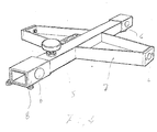
- the wheel marker arrangements 5 each constitutes a cross with six markers 6, one pair in each axial end and one on each of the radially arranged arms as can be seen in fig 4.
- the wheel marker arrangements 5 on the wheels has thus the shape of a cross with one end 8 of a bar fastened to a fastening bracket 9 and 10 respectively essentially as an extension of the wheel axle.
- transverse bars 11 of identical length are arranged in the front and rear and at their ends provided with marker arrangements 5.
- the markers are circular allowing for integration over the borderlines giving an extremely great precision.
- the markers have glass bead surfaces and thus reflects the infrared light from the camera back to this.
- the camera together with its software result in a precision laterally of fractions of millimeters and lengthwise of a few millimeters under the depicted conditions. This means that the camera 1 can register the coordinates for each marker with great accuracy, in turn meaning that the location of the markers relative the camera can be calculated as well as all the angles of the marker arrangements and thereby the wheel angles.
- each camera With the markers 5 and cameras 1 mounted as described above on each side of the lorry each camera is swung back so that it can register the lateral position of the crossbar 11 marker arrangements. The cameras are then allowed to swing back and register the position of the front cross bar marker arrangements giving the camera a reference relative the lorry that is parallel to the length axis of this. At the same time the angles of the rear wheel is obtained including a check if the rear axle is perpendicular to the length axis of the lorry. A deviation in this angle (thrust) give in particular rise to increased air resistance by the vehicle going obliquely through the air.
- the two-in corresponds to the detected lateral deviations for the radial markers from their actual lengthwise positions between the two axial markers. If for instance the radial marker in view seem to have moved slightly closer to the outer axial marker a two-in exist.
- Fig 3 shows the invention as used for a small passenger car.
- the camera 21 on the rear wheel 22 and the front wheel marker arrangements 24 function just as in the lorry case but with one axle less. Parallellity and the angles for the rear wheels are obtained when the camera registers the marker device positions for a reference crossbar that at its ends is provided with wheel marker arrangements.
- each wheel is rotated and adjustment is mechanically carried out to achieve concentric marker arrangements and or cameras.
- the camera can register the misalignment for diametrical readings and later use these for correction. Surprisingly this can also be achieved for the toe-in, however the front wheels may not move during the transfer of the camera from one side to the other.
- the marker reflections registered by the camera are actually direction coordinates for the reflected light beams, but since the computer has stored the true marker arrangement dimensions distance and angles can be calculated.
- the camera set infrared filter
- the markers are seen by the camera and no filtering step is necessary to clean the recorded image.
- reflectors LED s can be used which allows for coded light emission facilitating for the computer to distinguish different markers.
- a special reference axle 17 is provided for the mounting of a camera 1 or a pair of cameras at the ends.
- the reference axle is provided with stub axles of the same kind as the wheel mountings for the cameras and the camera is thus pivotable on these stub axles in the same way as on the wheel brackets and measuring can be carried out in the same way as described above.
- the stub axles 18 are actually ends of a common axle that is journaled for rotation in a fastening bracket for universal mounting to the rear or front of a car, bus or lorry or to a wall or a support of some kind.
- This reference axle is journaled for rotation but is provided with end stops permitting only a half revolution.
Landscapes
- Physics & Mathematics (AREA)
- General Physics & Mathematics (AREA)
- Length Measuring Devices By Optical Means (AREA)
- Vehicle Cleaning, Maintenance, Repair, Refitting, And Outriggers (AREA)
Applications Claiming Priority (2)
| Application Number | Priority Date | Filing Date | Title |
|---|---|---|---|
| SE9701927 | 1997-05-22 | ||
| SE9701927A SE512165C2 (sv) | 1997-05-22 | 1997-05-22 | Förfarande jämte anordning för mätning av fordons hjulvinklar |
Publications (2)
| Publication Number | Publication Date |
|---|---|
| EP0880009A2 true EP0880009A2 (de) | 1998-11-25 |
| EP0880009A3 EP0880009A3 (de) | 2000-11-02 |
Family
ID=20407053
Family Applications (1)
| Application Number | Title | Priority Date | Filing Date |
|---|---|---|---|
| EP98850084A Withdrawn EP0880009A3 (de) | 1997-05-22 | 1998-05-19 | Verfahren und Vorrichtung zum Messen von Radsatzwinkeln |
Country Status (4)
| Country | Link |
|---|---|
| US (1) | US6043875A (de) |
| EP (1) | EP0880009A3 (de) |
| JP (1) | JPH1151626A (de) |
| SE (1) | SE512165C2 (de) |
Cited By (9)
| Publication number | Priority date | Publication date | Assignee | Title |
|---|---|---|---|---|
| EP0943890A3 (de) * | 1998-03-16 | 2000-08-23 | CORGHI S.p.A. | Verfahren und Apparat zum Messen der karakteristischen Positionswinkel eines Fahrzeugs |
| WO2001011313A1 (de) * | 1999-08-05 | 2001-02-15 | Daimlerchrysler Ag | Zeitaufgelöste photogrammetrische messung von radstellungswerten |
| FR2830932A1 (fr) * | 2001-10-15 | 2003-04-18 | Muller Bem | Dispositif de controle de geometrie de vehicule a roue |
| WO2004061390A1 (de) * | 2002-12-20 | 2004-07-22 | Robert Bosch Gmbh | Vorrichtung zur bestimmung der rad- und/oder achsgeometrie von kraftfahrzeugen |
| WO2004111569A1 (en) * | 2003-06-11 | 2004-12-23 | Snap-On Incorporated | Wheel alignment with surface-oriented runout determination |
| EP1677071A1 (de) * | 2005-01-04 | 2006-07-05 | Snap-on Equipment Srl a unico socio. | Achsenvermessungsverfahren und -vorrichtung für mehrachsige Lastkraftwagen |
| CN102564356A (zh) * | 2010-09-13 | 2012-07-11 | 罗伯特·博世有限公司 | 汽车测量装置与方法 |
| US9739589B2 (en) | 2015-04-27 | 2017-08-22 | Juan Carlos SANTISTEBAN | Vehicle wheel alignment device |
| CN108426547A (zh) * | 2017-02-13 | 2018-08-21 | 株式会社大福 | 检查系统 |
Families Citing this family (12)
| Publication number | Priority date | Publication date | Assignee | Title |
|---|---|---|---|---|
| EP1277027B1 (de) * | 2000-04-25 | 2009-07-22 | Snap-on Incorporated | Spur- und achsvermessung an kraftfahrzeugen |
| US20040172170A1 (en) * | 2002-12-02 | 2004-09-02 | Lesert Brooks R. | Portable wheel alignment device |
| DE602004028598D1 (de) * | 2003-05-09 | 2010-09-23 | Snap On Tools Corp | Kameratechnik für die sensoreinstellung für die adaptive fahrtregelung (acc) |
| US7382913B2 (en) * | 2003-08-22 | 2008-06-03 | Hunter Engineering Company | Method and apparatus for guiding placement of vehicle service fixtures |
| SE531784C2 (sv) * | 2007-10-11 | 2009-08-04 | Jonas Samuelsson | Förfarande och anordning för hjulmätning |
| US8804107B2 (en) | 2010-02-26 | 2014-08-12 | Josam Ab | Method and system for wheel alignment of vehicles |
| JP6232306B2 (ja) * | 2013-02-08 | 2017-11-15 | 新明和工業株式会社 | 貨物自動車寸法測定装置 |
| JP5717041B1 (ja) * | 2014-11-03 | 2015-05-13 | 実 告野 | ホイールアライメント測定方法 |
| DE102017208608A1 (de) * | 2017-05-22 | 2018-11-22 | Robert Bosch Gmbh | Vorrichtung und Verfahren zur Fahrzeugvermessung |
| DE102017208627A1 (de) * | 2017-05-22 | 2018-11-22 | Robert Bosch Gmbh | Messsystem zur Fahrzeugvermessung |
| US10685505B2 (en) | 2017-11-28 | 2020-06-16 | GM Global Technology Operations LLC | Vehicle suspension system alignment monitoring |
| SE547899C2 (en) * | 2025-01-20 | 2025-12-16 | Car O Liner Group Ab | Camera housing arrangement, and wheel alignment measuring arrangement comprising such camera housing arrangement |
Family Cites Families (15)
| Publication number | Priority date | Publication date | Assignee | Title |
|---|---|---|---|---|
| US3777537A (en) * | 1971-02-05 | 1973-12-11 | Saab Scania Ab | Vehicle frame and body straightening devices |
| US4159574A (en) * | 1973-12-07 | 1979-07-03 | Erik Samuelsson | Method of measuring the angular position of the axis of rotation of a wheel |
| USD263019S (en) | 1979-01-03 | 1982-02-16 | Jonas Samuelsson | Drill harness |
| US4303338A (en) * | 1979-09-04 | 1981-12-01 | Ammco Tools, Inc. | Wheel alignment method and apparatus |
| SE468368B (sv) * | 1991-04-30 | 1992-12-21 | Jonas Samuelsson | Optoelektronisk maetskala foer att positionsbestaemma och indikera laeget foer ett mot maetskalan infallande riktat ljus fraan en straalningskaella |
| NO174025C (no) * | 1991-10-11 | 1994-03-02 | Metronor Sa | System for punktvis maaling av romlige koordinater |
| EP0674759B1 (de) * | 1992-09-04 | 2001-07-18 | Snap-on Technologies, Inc. | Verfahren und vorrichtung zur bestimmung der ausrichtung von kraftfahrzeugrädern |
| US5724743A (en) * | 1992-09-04 | 1998-03-10 | Snap-On Technologies, Inc. | Method and apparatus for determining the alignment of motor vehicle wheels |
| DE69406886T2 (de) * | 1993-10-11 | 1998-08-13 | Muller Bem | Verfahren und Vorrichtung zur geometrischen Kontrolle eines Fahrzeugs |
| SE502278C2 (sv) * | 1994-01-21 | 1995-09-25 | Jonas Samuelsson | Anordning för mätning av fordonshjulvinklar |
| US5600435A (en) * | 1995-05-24 | 1997-02-04 | Fori Automation, Inc. | Intelligent sensor method and apparatus for an optical wheel alignment machine |
| US5598358A (en) * | 1995-05-24 | 1997-01-28 | Hunter Engineering Company | Apparatus and method for calibrating vehicle wheel alignment instruments |
| JPH09133510A (ja) * | 1995-11-07 | 1997-05-20 | Sanyo Mach Works Ltd | ホイールアライメント測定方法 |
| US5675515A (en) * | 1995-12-28 | 1997-10-07 | Hunter Engineering Company | Apparatus and method for determining vehicle wheel alignment measurements from three dimensional wheel positions and orientations |
| US5724128A (en) * | 1995-12-28 | 1998-03-03 | Hunter Engineering Company | Apparatus and method for determining vehicle wheel alignment measurements from three dimensional wheel positions and orientations |
-
1997
- 1997-05-22 SE SE9701927A patent/SE512165C2/sv not_active IP Right Cessation
-
1998
- 1998-05-19 EP EP98850084A patent/EP0880009A3/de not_active Withdrawn
- 1998-05-20 US US09/082,371 patent/US6043875A/en not_active Expired - Lifetime
- 1998-05-22 JP JP10141007A patent/JPH1151626A/ja not_active Withdrawn
Cited By (14)
| Publication number | Priority date | Publication date | Assignee | Title |
|---|---|---|---|---|
| EP0943890A3 (de) * | 1998-03-16 | 2000-08-23 | CORGHI S.p.A. | Verfahren und Apparat zum Messen der karakteristischen Positionswinkel eines Fahrzeugs |
| WO2001011313A1 (de) * | 1999-08-05 | 2001-02-15 | Daimlerchrysler Ag | Zeitaufgelöste photogrammetrische messung von radstellungswerten |
| US7236240B1 (en) | 1999-08-05 | 2007-06-26 | Daimlerchrysler Ag | Time-resolved photogrammetric measurement of wheel position values |
| FR2830932A1 (fr) * | 2001-10-15 | 2003-04-18 | Muller Bem | Dispositif de controle de geometrie de vehicule a roue |
| WO2004061390A1 (de) * | 2002-12-20 | 2004-07-22 | Robert Bosch Gmbh | Vorrichtung zur bestimmung der rad- und/oder achsgeometrie von kraftfahrzeugen |
| US7380344B2 (en) | 2002-12-20 | 2008-06-03 | Robert Bosch Gmbh | Device for determining the wheel and/or axle geometry of motor vehicles |
| US7206716B2 (en) | 2003-06-11 | 2007-04-17 | Snap-On Incorporated | Wheel alignment with surface-oriented runout determination |
| WO2004111569A1 (en) * | 2003-06-11 | 2004-12-23 | Snap-On Incorporated | Wheel alignment with surface-oriented runout determination |
| EP1677071A1 (de) * | 2005-01-04 | 2006-07-05 | Snap-on Equipment Srl a unico socio. | Achsenvermessungsverfahren und -vorrichtung für mehrachsige Lastkraftwagen |
| CN102564356A (zh) * | 2010-09-13 | 2012-07-11 | 罗伯特·博世有限公司 | 汽车测量装置与方法 |
| CN102564356B (zh) * | 2010-09-13 | 2017-05-17 | 罗伯特·博世有限公司 | 汽车测量装置与方法 |
| US9739589B2 (en) | 2015-04-27 | 2017-08-22 | Juan Carlos SANTISTEBAN | Vehicle wheel alignment device |
| CN108426547A (zh) * | 2017-02-13 | 2018-08-21 | 株式会社大福 | 检查系统 |
| CN108426547B (zh) * | 2017-02-13 | 2021-07-30 | 株式会社大福 | 检查系统 |
Also Published As
| Publication number | Publication date |
|---|---|
| JPH1151626A (ja) | 1999-02-26 |
| EP0880009A3 (de) | 2000-11-02 |
| SE512165C2 (sv) | 2000-02-07 |
| SE9701927D0 (sv) | 1997-05-22 |
| US6043875A (en) | 2000-03-28 |
| SE9701927L (sv) | 1998-11-23 |
Similar Documents
| Publication | Publication Date | Title |
|---|---|---|
| US6043875A (en) | Method and device for the measuring of wheel angles | |
| JP4406506B2 (ja) | 自動車のホイールアラインメントおよびアクスルアラインメントを求めるための装置 | |
| US9778030B2 (en) | Method and apparatus for multi-axle vehicle alignment with vehicle frame reference | |
| EP0927335B1 (de) | Kalibrierung von kameras bei anwendung in radjustierung | |
| US6532062B2 (en) | Method and apparatus for measuring vehicle wheel scrub radius | |
| US8638452B2 (en) | Measuring head for a chassis measuring system, chassis measuring system and method for determining the position parameters of measuring heads of a chassis measuring system | |
| EP3243037B1 (de) | Rollende kalibrierung einer virtuellen radachse | |
| CN101055230B (zh) | 用于无接触式3d车轮校准的设备、系统和方法 | |
| US5056233A (en) | Method and apparatus for measuring cross-toe | |
| AU7442596A (en) | Method and apparatus for determining the alignment of motor vehicle wheels | |
| CN109996719B (zh) | 用于检测车辆的方向盘的方向盘位置、方向盘回转角和倾斜度的装置和方法 | |
| EP0943890B1 (de) | Verfahren und Apparat zum Messen der karakteristischen Positionswinkel eines Fahrzeugs | |
| US4430802A (en) | Vehicle wheel alignment testing apparatus | |
| US7415324B2 (en) | Vehicle wheel alignment adjustment method | |
| CN104937366A (zh) | 用于进行车辆测量的方法和装置 | |
| EP3425328B1 (de) | Verfahren zur bestimmung von spindelwinkeln | |
| EP2048473A1 (de) | Verfahren und Vorrichtung zum Messen von Winkeln von Rädern und Achsen | |
| US7532742B2 (en) | Two-wheel alignment adjustment method | |
| EP0611948B1 (de) | System zum Messen des Radstands eines Kraftfahrzeugrahmens und des Quer- und Längsversatzes seiner lenkbaren Räder | |
| US20160313110A1 (en) | Vehicle wheel alignment device | |
| EP1677071B1 (de) | Achsenvermessungsverfahren und -vorrichtung für mehrachsige Lastkraftwagen | |
| WO1998025106A1 (en) | Wheel alignment system | |
| KR101461423B1 (ko) | 타이어 얼라인먼트 검출장치 | |
| GB2274024A (en) | Angle sensor potentiometer for use in wheel alignment measuring system |
Legal Events
| Date | Code | Title | Description |
|---|---|---|---|
| PUAI | Public reference made under article 153(3) epc to a published international application that has entered the european phase |
Free format text: ORIGINAL CODE: 0009012 |
|
| AK | Designated contracting states |
Kind code of ref document: A2 Designated state(s): DE FR GB IT NL SE |
|
| AX | Request for extension of the european patent |
Free format text: AL;LT;LV;MK;RO;SI |
|
| PUAL | Search report despatched |
Free format text: ORIGINAL CODE: 0009013 |
|
| AK | Designated contracting states |
Kind code of ref document: A3 Designated state(s): AT BE CH CY DE DK ES FI FR GB GR IE IT LI LU MC NL PT SE |
|
| AX | Request for extension of the european patent |
Free format text: AL;LT;LV;MK;RO;SI |
|
| 17P | Request for examination filed |
Effective date: 20010502 |
|
| AKX | Designation fees paid |
Free format text: DE FR GB IT NL SE |
|
| 17Q | First examination report despatched |
Effective date: 20050307 |
|
| STAA | Information on the status of an ep patent application or granted ep patent |
Free format text: STATUS: THE APPLICATION IS DEEMED TO BE WITHDRAWN |
|
| 18D | Application deemed to be withdrawn |
Effective date: 20050719 |