EP0880155A1 - Elektrisches Schloss durch einen Schalter gesteuert welche verhindert sein kann - Google Patents
Elektrisches Schloss durch einen Schalter gesteuert welche verhindert sein kann Download PDFInfo
- Publication number
- EP0880155A1 EP0880155A1 EP98401022A EP98401022A EP0880155A1 EP 0880155 A1 EP0880155 A1 EP 0880155A1 EP 98401022 A EP98401022 A EP 98401022A EP 98401022 A EP98401022 A EP 98401022A EP 0880155 A1 EP0880155 A1 EP 0880155A1
- Authority
- EP
- European Patent Office
- Prior art keywords
- switch
- enclosure
- control
- control member
- translation
- Prior art date
- Legal status (The legal status is an assumption and is not a legal conclusion. Google has not performed a legal analysis and makes no representation as to the accuracy of the status listed.)
- Granted
Links
- 230000000903 blocking effect Effects 0.000 claims abstract description 7
- 238000006073 displacement reaction Methods 0.000 claims description 3
- 230000002401 inhibitory effect Effects 0.000 claims 1
- 230000003213 activating effect Effects 0.000 abstract 1
- 239000003112 inhibitor Substances 0.000 abstract 1
- 241001441732 Ostraciidae Species 0.000 description 2
- 230000000694 effects Effects 0.000 description 2
- 230000005764 inhibitory process Effects 0.000 description 2
- 210000000056 organ Anatomy 0.000 description 2
- 239000007787 solid Substances 0.000 description 1
- 238000003466 welding Methods 0.000 description 1
Images


Classifications
-
- H—ELECTRICITY
- H01—ELECTRIC ELEMENTS
- H01H—ELECTRIC SWITCHES; RELAYS; SELECTORS; EMERGENCY PROTECTIVE DEVICES
- H01H13/00—Switches having rectilinearly-movable operating part or parts adapted for pushing or pulling in one direction only, e.g. push-button switch
- H01H13/02—Details
- H01H13/12—Movable parts; Contacts mounted thereon
- H01H13/20—Driving mechanisms
-
- H—ELECTRICITY
- H01—ELECTRIC ELEMENTS
- H01H—ELECTRIC SWITCHES; RELAYS; SELECTORS; EMERGENCY PROTECTIVE DEVICES
- H01H3/00—Mechanisms for operating contacts
- H01H3/54—Mechanisms for coupling or uncoupling operating parts, driving mechanisms, or contacts
Definitions
- the present invention relates to electric locks for closing the wing of an enclosure, in particular for closing of a motor vehicle trunk.
- Such locks include a locking member for block the leaf in the closed position, electrical means to put the locking member in the inactive position, and at least one switch controlling the electrical supply of these means.
- a main switch is provided with a control element on which can act a control member operable from outside the enclosure.
- Such a lock when used for closing of the trunk lid of the vehicle, does not have all the safety, because when the vehicle during its journey is brought to stop, an individual can actuate this control member to open the safe and steal its contents.
- the lock defined above comprises means that can be actuated from the inside of the enclosure, for example from inside a vehicle trunk automotive, to inhibit the action of the control member on the main switch.
- an auxiliary switch is can be operated from inside the vehicle cabin to allow the opening of the lock even after the organ of control associated with the main switch.
- the invention therefore relates to a lock electric for closing the leaf of an enclosure, comprising a locking member for locking the leaf in the closed position, electrical retraction means for placing in the inactive position said blocking member, a switch controlling the supply electric of said retraction means, and a control member actuable from outside the enclosure, capable of acting on a control element of said switch, characterized in that it further includes means operable from within the enclosure, to inhibit the action of said control member.
- An actuating element such as a push button, accessible from the outside, integral in translation with said member control, allows the user to move in translation the ordered.
- the rotational movement of the organ of order can only be produced from inside the enclosure, at by means of an actuating element such as a joystick, accessible from inside the enclosure, integral in rotation with said member ordered.
- the control is a cylindrical part mounted movable in translation axial and rotating in a housing of corresponding shape.
- the element for rotating the said part accessible from inside the enclosure, is a controller made in one piece with said part, in the form of a projecting part of the latter, extending radially with respect to the axis of translation of the part, passing through the housing through an opening of the latter and extending to the outside of the case.
- the actuator accessible from the outside is a push button which is mounted axially movable in the housing, coaxially and contiguously with said piece of ordered. Common means of recall are also provided to simultaneously press the push button towards its rest position and the control part against said push button.
- This preferred form of implementation of the invention has the advantage of simply carrying out in one piece the control part and its rotation actuating handle, and to use the same recall means to ensure, on the one hand, the return of the control panel and the push button in their rest position and, on the other hand, the securing in translation of these two elements.
- Means are also provided for making these two extreme positions of the displacement path of the switch so that when the element is actuated control of the switch by the control member, the forces exerted on the switch do not move it.
- An actuating element such as a push button, accessible from outside the enclosure, integral in translation with said control member, allows the user to move in translation the control member against return means.
- the translational movement of the switch can only be produced from inside the enclosure, by means of an actuating element such as a lever, integral in translation with said switch.
- the push button is made in one piece with a generally shaped piece cylindrical forming the control member, which is movably mounted in translation in a housing of corresponding shape.
- the switch is mounted on a mobile support in translation in the housing, on a limited trajectory.
- the actuator in translation of said switch support, accessible from inside the enclosure is a lever made in one piece with said support, in the form of a projecting part of this support, extending radially with respect to the axis of translation of said support, this part protruding through the housing through an opening of the latter and extending outside of said housing.
- This last preferred form of implementation of the invention has the advantage of making it simple, in a single part, the push button and the control part while allowing inhibition of the action of the control part on the switch, as recommended by the invention.
- FIGS. 1 to 6 represent a first embodiment of an electric lock according to the invention.
- the lock includes: a housing cylindrical formed by a barrel 1 and a bottom 2; a switch 3 fixed on the bottom 2; a control part 4 of hollow cylindrical shape, mounted in the housing (1, 2) to be able to both slide axially and rotate around its axis; and a mounted push button 5 coaxially with the control piece 4 and contiguously with this last.
- the cylinder 1 is completely open at one end 1a, and it has at its other end, a coaxial annular wall 6 forming a flange for attachment, by any suitable means such as welding, riveting, etc., the housing 1, 2 on a wall 7 of a motor vehicle trunk.
- the bottom of the case 2 has, on its face facing the inside of the case, a projecting part in the shape of a stirrup 8 forming a fixing member for the switch 3.
- the bottom 2 is also provided externally with clipping fins 9 each capable of cooperating with a corresponding clipping tenon 10 provided on the circumference face of the barrel 1, not far from the end 1a of the latter.
- Switch 3 is interposed in an electrical circuit allowing the electrical supply of means controlling the setting in retracted position of a locking element, such as a bolt, of the cover the trunk of the vehicle.
- Said electrical circuit, said means of control and said blocking element are not shown on the drawings and they will not be further described herein description, being well known to those skilled in the art.
- the pushbutton 5 comprises: a cylindrical portion 5A with small clearance through the opening 6a of the annular wall 6, and projecting outside the casing; and a flange portion 5 b of diameter greater than that of the opening 6 a , housed in the barrel 1.
- the control part 4 is open at its end 4a facing the base 2.
- the portion fixing member 8 and the switch 3 penetrate through the open end 4 has in the part 4 and extend inside of the latter.
- Two return coil springs 11 with axes parallel to that of the housing, are accommodated each in a partially blind hole 11a formed from the end face, side end 4 a of the gear portion 4, and are interposed between the bottom 2 and the control part 4.
- Their function is to recall the part 4 and the push button 5, which is joined to it by its face 5 c on the flange side 5 b , in their rest position for which the flange 5 b is in abutment against the annular wall 6.
- the components of lock 1, 2, 4, 11 are arranged and dimensioned so that the springs 11 are still in the pre-stressed state, and that remains between the control 4 and bottom 2 a movement d, when no thrust is exerted on the push button 5 in the rest position (see Figure 3).
- the springs 11 constitute both means elastic bands for push button 5 and control panel 4 and means for urging the control part 4 against the push-button 5 so as to secure it in translation of these last two elements.
- the control part 4 also has a projecting part 12, extending radially relative to the axis of translation of the part 4, extending outside the housing 1, 2 and passing through it through an opening of rectangular shape 13 formed in the wall of the barrel 1 from its end 1 a .
- the protruding part 12 forms a lever for actuating the control part 4 in rotation, this lever being accessible only from inside the boot of the vehicle.
- a ball 90 pushed by a spring 91 is disposed in a housing 92 which opens onto the side wall of the control part 4; the ball 90 is pushed outwards and can thus cooperate with two grooves 93 formed on the internal side wall of the barrel 1 to constitute elastic stops corresponding to the two end of rotational travel of the part 4 relative to the barrel 1.
- the grooves 93 are parallel to the axis of barrel 1.
- the opening 13 is angularly delimited by longitudinal edges 13 a which limit the possible rotary clearance for the lever 12.
- the control part 4 has the function of actuating a control element 3 a of the switch to change the position, open or closed, of the latter in the opposite position, closed or open.
- the part 4 has a protrusion 14 projecting from the face facing the switch 3, from the solid bottom wall 4 b of the part 4.
- control part 4 can be put, by pivoting around its axis in two angular positions such as: in one of these positions, called active, represented on the Figure 5, the protrusion 14 is located opposite the control element 3 a ; in the other so-called inactive position, shown in FIG. 6, the protrusion 14 is angularly offset relative to the control element 3 a .
- the protrusion 14 is dimensioned so that, when the control part 4 is in its active angular position (with reference to its rotation about its axis), and, in its position of pushed translation (with reference to its translation parallel to its axis), as shown in FIG. 4, said protuberance 14 presses on the control element 3a of the switch 3, and when the control part 4 is in its active angular position and in its position in translation of rest, as shown in Figure 3, said protuberance 14 is spaced from said control element 3 a .
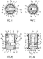
- FIGS. 7 to 14 show a second mode of realization of the invention.
- identical elements or analogous to those of FIGS. 1 to 6 bear identical references.
- the bottom 20 of the housing has two spaced cylindrical segment shaped wings one of the other 21 extending longitudinally inside the housing and delimiting between itself a profiled space, in which is housed axially sliding a slider 22 on which the switch 3 is fixed of the electric lock.
- the cursor 22 has a shaped recess 23 and dimensioned so as to be able to receive practically without play body of the switch 3.
- the fixing of the switch 3 on the slider 22 is provided by two sliders 24 of cursor 22, each adjusting in a corresponding through hole 25 formed in the body of switch 3.
- the control member consists of a generally cylindrical part 40 mounted in the housing to be able to slide axially.
- the piece 40 includes a finger 41 extending axially in the direction of the bottom 20 of the housing, and having at its free end a bevelled part forming an inclined face 41 a cam for actuating the control element 3 has the switch 3.
- the part 40 On the side opposite the finger 41, the part 40 has an extension portion of smaller section 42 projecting outside the housing 1, 20, forming a push button.
- the projecting part 42 has a generally cylindrical shape flanked by two diametrically opposite bosses 42 a, giving said part 42 a non-circular section.
- the opening 60 a of the annular wall 60 fixed to one end of the barrel 1 has a shape corresponding to the cross section of the part 42 which passes through said opening 60 a with little lateral play.
- the bosses 42 a have the function of preventing any rotation about its axis of the part 40.
- the part 40 constitutes both the control member and the lock push button.
- Two return coil springs 11 with axes parallel to that of the housing 1, 20, are each housed in a partially blind hole 11a formed from the end face of a corresponding wing 21. Their function is to recall the part 40 in its rest position for which the shoulder 43 formed between the projecting part 42 and the rest, of larger section, of the part 40, is in abutment against the annular wall 60.
- the slider 22 has a housing 26 extending transversely to the sliding axis of the cursor. This housing receives a ball 27 pushed by a spring 28. The ball 27 is intended to engage in one or the other of two grooves 29 formed in the inner face of one of the wings 21 of the bottom 20.
- the set of elements 26 to 29 constitutes a means for defining two stable end positions of the sliding slide limit switch 22.
- the cursor 22 also has a projecting part 30 forming a lever for actuating the cursor in translation 22.
- the part 30 extends transversely relative to the sliding direction of the cursor, crosses the barrel 1 through a rectangular opening 31 formed in the barrel 1 from its open end 1a, and extends outside the housing 1, 20.
- the opening 31 is sized to allow free movement with slight lateral play, the handle 30.
- the end positions of the cursor 22 are defined by the position of the grooves 29.
- Figures 9, 10 and 14 show the cursor 22 in the so-called active position, for which the control member 3 a of the switch 3 is located. on the trajectory of the inclined surface 41 a of the control part 40.
- the cursor 22 has been shown in the so-called inactive position, for which the control element 3 a of the switch 3 is outside the trajectory of the inclined surface 41 a .
- Elements 21 and 40 are shaped and dimensioned so that, in the rest position of the part 40, remains between this last and the end face of the wings 21 of the bottom 20 a movement d1 constituting the length of the push button pushing stroke 42.
Landscapes
- Mechanical Control Devices (AREA)
- Lock And Its Accessories (AREA)
- Push-Button Switches (AREA)
Applications Claiming Priority (2)
| Application Number | Priority Date | Filing Date | Title |
|---|---|---|---|
| FR9706095A FR2763626B1 (fr) | 1997-05-20 | 1997-05-20 | Serrure electrique commandee par un interrupteur susceptible d'etre inhibe |
| FR9706095 | 1997-05-20 |
Publications (2)
| Publication Number | Publication Date |
|---|---|
| EP0880155A1 true EP0880155A1 (de) | 1998-11-25 |
| EP0880155B1 EP0880155B1 (de) | 2003-07-02 |
Family
ID=9507008
Family Applications (1)
| Application Number | Title | Priority Date | Filing Date |
|---|---|---|---|
| EP19980401022 Revoked EP0880155B1 (de) | 1997-05-20 | 1998-04-27 | Elektrischer Schlie mechanismus, der durch einen blockierbaren Schalter geschaltet wird. |
Country Status (4)
| Country | Link |
|---|---|
| EP (1) | EP0880155B1 (de) |
| DE (1) | DE69815947T8 (de) |
| ES (1) | ES2202767T3 (de) |
| FR (1) | FR2763626B1 (de) |
Citations (4)
| Publication number | Priority date | Publication date | Assignee | Title |
|---|---|---|---|---|
| CH523587A (de) * | 1971-04-23 | 1972-05-31 | Siemens Ag Albis | Schalteranordnung an einem Infrarotsichtgerät zum Ein- und Ausschalten von dessen Strahlungsquelle |
| FR2408904A1 (fr) * | 1977-11-15 | 1979-06-08 | Telemecanique Electrique | Dispositif pour la commande des mouvements d'une machine, en particulier d'appareil de levage |
| GB2207284A (en) * | 1987-07-24 | 1989-01-25 | Triumph Adler Ag | Key-disabled membrane switch |
| DE3838362C1 (de) * | 1988-11-11 | 1990-01-11 | Nixdorf Computer Ag, 4790 Paderborn, De |
-
1997
- 1997-05-20 FR FR9706095A patent/FR2763626B1/fr not_active Expired - Fee Related
-
1998
- 1998-04-27 DE DE1998615947 patent/DE69815947T8/de active Active
- 1998-04-27 ES ES98401022T patent/ES2202767T3/es not_active Expired - Lifetime
- 1998-04-27 EP EP19980401022 patent/EP0880155B1/de not_active Revoked
Patent Citations (4)
| Publication number | Priority date | Publication date | Assignee | Title |
|---|---|---|---|---|
| CH523587A (de) * | 1971-04-23 | 1972-05-31 | Siemens Ag Albis | Schalteranordnung an einem Infrarotsichtgerät zum Ein- und Ausschalten von dessen Strahlungsquelle |
| FR2408904A1 (fr) * | 1977-11-15 | 1979-06-08 | Telemecanique Electrique | Dispositif pour la commande des mouvements d'une machine, en particulier d'appareil de levage |
| GB2207284A (en) * | 1987-07-24 | 1989-01-25 | Triumph Adler Ag | Key-disabled membrane switch |
| DE3838362C1 (de) * | 1988-11-11 | 1990-01-11 | Nixdorf Computer Ag, 4790 Paderborn, De |
Also Published As
| Publication number | Publication date |
|---|---|
| FR2763626B1 (fr) | 1999-07-16 |
| EP0880155B1 (de) | 2003-07-02 |
| DE69815947T8 (de) | 2004-09-23 |
| DE69815947T2 (de) | 2004-05-27 |
| DE69815947D1 (de) | 2003-08-07 |
| ES2202767T3 (es) | 2004-04-01 |
| FR2763626A1 (fr) | 1998-11-27 |
Similar Documents
| Publication | Publication Date | Title |
|---|---|---|
| EP3399532B1 (de) | Nothaltevorrichtung | |
| FR2948402A1 (fr) | Commande d'ouverture exterieure d'un ouvrant de vehicule automobile et ouvrant equipe d'une telle commande d'ouverture | |
| EP0509870A1 (de) | Handbremse für ein Fahrzeug | |
| FR2852993A1 (fr) | Serrure pour ouvrant de vehicule automobile, a memorisation de decondamnation/condamnation | |
| EP3670798A1 (de) | Öffnungskontrolle mit mechanischer zusammenbau | |
| FR2534304A1 (fr) | Serrure a poussoir, en particulier pour volet mobile de la boite a gants d'un vehicule automobile | |
| EP1729313B1 (de) | Antriebsvorrichtung eines elektischen Schaltgerätes mit Schaltsperre | |
| EP1004730B1 (de) | Schloss für die vordere oder hintere Tür eines Kraftfahrzeuges | |
| FR2747230A1 (fr) | Bouton d'arret d'urgence cadenassable | |
| EP1291479B1 (de) | Schloss mit Universalaufstellung | |
| CH666369A5 (fr) | Appareil interrupteur d'urgence commandant un interrupteur electrique. | |
| EP0880155B1 (de) | Elektrischer Schlie mechanismus, der durch einen blockierbaren Schalter geschaltet wird. | |
| FR3127006A1 (fr) | Dispositif de commande d’ouverture extérieure d’un ouvrant de véhicule automobile. | |
| EP0906997A1 (de) | Verriegelungsvorrichtung mit einem nockenbetätigten Übertragungselement | |
| EP3808925B1 (de) | Schloss für einen öffnungsflügel eines kraftfahrzeugs | |
| FR2971536A1 (fr) | Dispositif de commande de l'ouverture interieure d'un ouvrant a bouton poussoir et tendeur de cable. | |
| EP1605123B1 (de) | Öffnungs- und Schliessmechanismus für Kraftfahrzeugtür | |
| FR2691496A1 (fr) | Verrou à rotor débrayable, notamment pour serrure de véhicule automobile. | |
| WO2011061276A1 (fr) | Cle a insert escamotable | |
| FR2792964A1 (fr) | Serrure manoeuvrable electriquement ou mecaniquement | |
| EP1378621B1 (de) | Kupplungsmechanismus zum Betätigen eines Schlosses und eine damit ausgerüstete Tür | |
| FR2769938A1 (fr) | Serrure electrique commandee par un interrupteur susceptible d'etre inhibe | |
| FR2812328A1 (fr) | Dispositif de rattrapage automatique du quart de tour a vide dans un cylindre ou serrure a disques | |
| EP2935729A1 (de) | Schlüssel mit herausklappbarem einsatz mit spielraumeinschränkung | |
| EP0908587A1 (de) | Kombinationsschloss |
Legal Events
| Date | Code | Title | Description |
|---|---|---|---|
| PUAI | Public reference made under article 153(3) epc to a published international application that has entered the european phase |
Free format text: ORIGINAL CODE: 0009012 |
|
| AK | Designated contracting states |
Kind code of ref document: A1 Designated state(s): DE ES GB IT |
|
| AX | Request for extension of the european patent |
Free format text: AL;LT;LV;MK;RO;SI |
|
| 17P | Request for examination filed |
Effective date: 19990226 |
|
| AKX | Designation fees paid |
Free format text: DE ES GB IT |
|
| GRAG | Despatch of communication of intention to grant |
Free format text: ORIGINAL CODE: EPIDOS AGRA |
|
| 17Q | First examination report despatched |
Effective date: 20010821 |
|
| GRAG | Despatch of communication of intention to grant |
Free format text: ORIGINAL CODE: EPIDOS AGRA |
|
| GRAG | Despatch of communication of intention to grant |
Free format text: ORIGINAL CODE: EPIDOS AGRA |
|
| GRAH | Despatch of communication of intention to grant a patent |
Free format text: ORIGINAL CODE: EPIDOS IGRA |
|
| GRAH | Despatch of communication of intention to grant a patent |
Free format text: ORIGINAL CODE: EPIDOS IGRA |
|
| GRAA | (expected) grant |
Free format text: ORIGINAL CODE: 0009210 |
|
| AK | Designated contracting states |
Designated state(s): DE ES GB IT |
|
| REG | Reference to a national code |
Ref country code: GB Ref legal event code: FG4D Free format text: NOT ENGLISH |
|
| REF | Corresponds to: |
Ref document number: 69815947 Country of ref document: DE Date of ref document: 20030807 Kind code of ref document: P |
|
| GBT | Gb: translation of ep patent filed (gb section 77(6)(a)/1977) | ||
| REG | Reference to a national code |
Ref country code: ES Ref legal event code: FG2A Ref document number: 2202767 Country of ref document: ES Kind code of ref document: T3 |
|
| PLBQ | Unpublished change to opponent data |
Free format text: ORIGINAL CODE: EPIDOS OPPO |
|
| PLBI | Opposition filed |
Free format text: ORIGINAL CODE: 0009260 |
|
| PLAX | Notice of opposition and request to file observation + time limit sent |
Free format text: ORIGINAL CODE: EPIDOSNOBS2 |
|
| 26 | Opposition filed |
Opponent name: DELPHI TECHNOLOGIES, INC. Effective date: 20040401 |
|
| PLAX | Notice of opposition and request to file observation + time limit sent |
Free format text: ORIGINAL CODE: EPIDOSNOBS2 |
|
| PLBB | Reply of patent proprietor to notice(s) of opposition received |
Free format text: ORIGINAL CODE: EPIDOSNOBS3 |
|
| PLAY | Examination report in opposition despatched + time limit |
Free format text: ORIGINAL CODE: EPIDOSNORE2 |
|
| PLBC | Reply to examination report in opposition received |
Free format text: ORIGINAL CODE: EPIDOSNORE3 |
|
| PLAT | Information related to reply to examination report in opposition deleted |
Free format text: ORIGINAL CODE: EPIDOSDORE3 |
|
| PLAY | Examination report in opposition despatched + time limit |
Free format text: ORIGINAL CODE: EPIDOSNORE2 |
|
| PLAH | Information related to despatch of examination report in opposition + time limit modified |
Free format text: ORIGINAL CODE: EPIDOSCORE2 |
|
| PLBC | Reply to examination report in opposition received |
Free format text: ORIGINAL CODE: EPIDOSNORE3 |
|
| APBM | Appeal reference recorded |
Free format text: ORIGINAL CODE: EPIDOSNREFNO |
|
| APBP | Date of receipt of notice of appeal recorded |
Free format text: ORIGINAL CODE: EPIDOSNNOA2O |
|
| APAH | Appeal reference modified |
Free format text: ORIGINAL CODE: EPIDOSCREFNO |
|
| APBA | Date of receipt of statement of grounds of appeal deleted |
Free format text: ORIGINAL CODE: EPIDOSDNOA3O |
|
| APBM | Appeal reference recorded |
Free format text: ORIGINAL CODE: EPIDOSNREFNO |
|
| APBP | Date of receipt of notice of appeal recorded |
Free format text: ORIGINAL CODE: EPIDOSNNOA2O |
|
| APBQ | Date of receipt of statement of grounds of appeal recorded |
Free format text: ORIGINAL CODE: EPIDOSNNOA3O |
|
| APBQ | Date of receipt of statement of grounds of appeal recorded |
Free format text: ORIGINAL CODE: EPIDOSNNOA3O |
|
| RAP2 | Party data changed (patent owner data changed or rights of a patent transferred) |
Owner name: VALEO SECURITE HABITACLE |
|
| PGFP | Annual fee paid to national office [announced via postgrant information from national office to epo] |
Ref country code: DE Payment date: 20120416 Year of fee payment: 15 |
|
| PGFP | Annual fee paid to national office [announced via postgrant information from national office to epo] |
Ref country code: GB Payment date: 20120423 Year of fee payment: 15 |
|
| PGFP | Annual fee paid to national office [announced via postgrant information from national office to epo] |
Ref country code: IT Payment date: 20120423 Year of fee payment: 15 |
|
| REG | Reference to a national code |
Ref country code: DE Ref legal event code: R103 Ref document number: 69815947 Country of ref document: DE Ref country code: DE Ref legal event code: R064 Ref document number: 69815947 Country of ref document: DE |
|
| APBU | Appeal procedure closed |
Free format text: ORIGINAL CODE: EPIDOSNNOA9O |
|
| PGFP | Annual fee paid to national office [announced via postgrant information from national office to epo] |
Ref country code: ES Payment date: 20120425 Year of fee payment: 15 |
|
| RDAF | Communication despatched that patent is revoked |
Free format text: ORIGINAL CODE: EPIDOSNREV1 |
|
| RDAG | Patent revoked |
Free format text: ORIGINAL CODE: 0009271 |
|
| STAA | Information on the status of an ep patent application or granted ep patent |
Free format text: STATUS: PATENT REVOKED |
|
| 27W | Patent revoked |
Effective date: 20121112 |
|
| GBPR | Gb: patent revoked under art. 102 of the ep convention designating the uk as contracting state |
Effective date: 20121112 |
|
| REG | Reference to a national code |
Ref country code: DE Ref legal event code: R107 Ref document number: 69815947 Country of ref document: DE Effective date: 20130926 |