EP0880710B1 - Systeme de gestion de batterie et simulateur de batterie - Google Patents
Systeme de gestion de batterie et simulateur de batterie Download PDFInfo
- Publication number
- EP0880710B1 EP0880710B1 EP97909545A EP97909545A EP0880710B1 EP 0880710 B1 EP0880710 B1 EP 0880710B1 EP 97909545 A EP97909545 A EP 97909545A EP 97909545 A EP97909545 A EP 97909545A EP 0880710 B1 EP0880710 B1 EP 0880710B1
- Authority
- EP
- European Patent Office
- Prior art keywords
- battery
- temperature
- management system
- representation
- physical quantity
- Prior art date
- Legal status (The legal status is an assumption and is not a legal conclusion. Google has not performed a legal analysis and makes no representation as to the accuracy of the status listed.)
- Expired - Lifetime
Links
- 238000006243 chemical reaction Methods 0.000 claims description 93
- 238000007600 charging Methods 0.000 claims description 62
- 238000012545 processing Methods 0.000 claims description 31
- 238000000034 method Methods 0.000 claims description 27
- 238000003860 storage Methods 0.000 claims description 27
- 238000007086 side reaction Methods 0.000 claims description 25
- 238000007599 discharging Methods 0.000 claims description 24
- 238000011161 development Methods 0.000 claims description 23
- 238000012546 transfer Methods 0.000 claims description 19
- 239000003792 electrolyte Substances 0.000 claims description 18
- 239000000463 material Substances 0.000 claims description 16
- 230000008859 change Effects 0.000 claims description 14
- 238000003487 electrochemical reaction Methods 0.000 claims description 13
- 238000004519 manufacturing process Methods 0.000 claims description 7
- 239000000126 substance Substances 0.000 claims description 7
- 239000000203 mixture Substances 0.000 claims description 6
- 230000037427 ion transport Effects 0.000 claims description 5
- 230000004044 response Effects 0.000 claims description 5
- PXHVJJICTQNCMI-UHFFFAOYSA-N Nickel Chemical compound [Ni] PXHVJJICTQNCMI-UHFFFAOYSA-N 0.000 description 127
- 239000001301 oxygen Substances 0.000 description 54
- 229910052760 oxygen Inorganic materials 0.000 description 54
- QVGXLLKOCUKJST-UHFFFAOYSA-N atomic oxygen Chemical compound [O] QVGXLLKOCUKJST-UHFFFAOYSA-N 0.000 description 53
- 229910052793 cadmium Inorganic materials 0.000 description 44
- 230000006399 behavior Effects 0.000 description 41
- BDOSMKKIYDKNTQ-UHFFFAOYSA-N cadmium atom Chemical compound [Cd] BDOSMKKIYDKNTQ-UHFFFAOYSA-N 0.000 description 40
- 238000009792 diffusion process Methods 0.000 description 36
- 229910005580 NiCd Inorganic materials 0.000 description 33
- 229910052759 nickel Inorganic materials 0.000 description 33
- 230000000694 effects Effects 0.000 description 22
- 229910021508 nickel(II) hydroxide Inorganic materials 0.000 description 21
- 230000006798 recombination Effects 0.000 description 21
- 238000005215 recombination Methods 0.000 description 21
- 239000000047 product Substances 0.000 description 19
- 230000018109 developmental process Effects 0.000 description 18
- 239000007789 gas Substances 0.000 description 17
- 239000003990 capacitor Substances 0.000 description 16
- 230000008569 process Effects 0.000 description 15
- 238000004088 simulation Methods 0.000 description 14
- 238000007254 oxidation reaction Methods 0.000 description 13
- 238000006722 reduction reaction Methods 0.000 description 13
- 230000006870 function Effects 0.000 description 12
- 230000003647 oxidation Effects 0.000 description 11
- 230000036961 partial effect Effects 0.000 description 11
- 238000013461 design Methods 0.000 description 9
- 230000004913 activation Effects 0.000 description 8
- 230000001276 controlling effect Effects 0.000 description 8
- 230000032258 transport Effects 0.000 description 8
- 238000013459 approach Methods 0.000 description 7
- 229910001416 lithium ion Inorganic materials 0.000 description 7
- 230000009467 reduction Effects 0.000 description 7
- 229910002640 NiOOH Inorganic materials 0.000 description 6
- 230000007423 decrease Effects 0.000 description 6
- 239000007772 electrode material Substances 0.000 description 6
- 239000002245 particle Substances 0.000 description 6
- 230000015572 biosynthetic process Effects 0.000 description 5
- 230000001419 dependent effect Effects 0.000 description 5
- 238000005259 measurement Methods 0.000 description 5
- 239000012071 phase Substances 0.000 description 5
- 230000002829 reductive effect Effects 0.000 description 5
- 238000010277 constant-current charging Methods 0.000 description 4
- 238000010586 diagram Methods 0.000 description 4
- 238000004364 calculation method Methods 0.000 description 3
- 230000008878 coupling Effects 0.000 description 3
- 238000010168 coupling process Methods 0.000 description 3
- 238000005859 coupling reaction Methods 0.000 description 3
- 238000004146 energy storage Methods 0.000 description 3
- 229920000642 polymer Polymers 0.000 description 3
- 238000000926 separation method Methods 0.000 description 3
- OKTJSMMVPCPJKN-UHFFFAOYSA-N Carbon Chemical compound [C] OKTJSMMVPCPJKN-UHFFFAOYSA-N 0.000 description 2
- UFHFLCQGNIYNRP-UHFFFAOYSA-N Hydrogen Chemical compound [H][H] UFHFLCQGNIYNRP-UHFFFAOYSA-N 0.000 description 2
- WMFOQBRAJBCJND-UHFFFAOYSA-M Lithium hydroxide Chemical compound [Li+].[OH-] WMFOQBRAJBCJND-UHFFFAOYSA-M 0.000 description 2
- 229910005813 NiMH Inorganic materials 0.000 description 2
- 238000013528 artificial neural network Methods 0.000 description 2
- 230000015556 catabolic process Effects 0.000 description 2
- 238000010280 constant potential charging Methods 0.000 description 2
- 230000003247 decreasing effect Effects 0.000 description 2
- 238000006731 degradation reaction Methods 0.000 description 2
- 238000000151 deposition Methods 0.000 description 2
- 238000004090 dissolution Methods 0.000 description 2
- 238000002474 experimental method Methods 0.000 description 2
- 230000004907 flux Effects 0.000 description 2
- 229910052739 hydrogen Inorganic materials 0.000 description 2
- 239000001257 hydrogen Substances 0.000 description 2
- 230000000670 limiting effect Effects 0.000 description 2
- 229910052751 metal Inorganic materials 0.000 description 2
- 239000002184 metal Substances 0.000 description 2
- 150000002739 metals Chemical class 0.000 description 2
- 238000001556 precipitation Methods 0.000 description 2
- 238000005070 sampling Methods 0.000 description 2
- 239000007787 solid Substances 0.000 description 2
- 239000006104 solid solution Substances 0.000 description 2
- 239000000243 solution Substances 0.000 description 2
- 238000006276 transfer reaction Methods 0.000 description 2
- MYMOFIZGZYHOMD-UHFFFAOYSA-N Dioxygen Chemical compound O=O MYMOFIZGZYHOMD-UHFFFAOYSA-N 0.000 description 1
- 239000002000 Electrolyte additive Substances 0.000 description 1
- 229910006148 NiII Inorganic materials 0.000 description 1
- 230000032683 aging Effects 0.000 description 1
- 239000012670 alkaline solution Substances 0.000 description 1
- 238000004458 analytical method Methods 0.000 description 1
- 150000001661 cadmium Chemical class 0.000 description 1
- PLLZRTNVEXYBNA-UHFFFAOYSA-L cadmium hydroxide Chemical compound [OH-].[OH-].[Cd+2] PLLZRTNVEXYBNA-UHFFFAOYSA-L 0.000 description 1
- 229910052799 carbon Inorganic materials 0.000 description 1
- 239000011248 coating agent Substances 0.000 description 1
- 238000000576 coating method Methods 0.000 description 1
- 238000004891 communication Methods 0.000 description 1
- 239000002482 conductive additive Substances 0.000 description 1
- 239000004020 conductor Substances 0.000 description 1
- 238000010276 construction Methods 0.000 description 1
- 238000007796 conventional method Methods 0.000 description 1
- 238000012937 correction Methods 0.000 description 1
- 238000000354 decomposition reaction Methods 0.000 description 1
- 229910001882 dioxygen Inorganic materials 0.000 description 1
- 238000003411 electrode reaction Methods 0.000 description 1
- 239000008151 electrolyte solution Substances 0.000 description 1
- 229910002804 graphite Inorganic materials 0.000 description 1
- 239000010439 graphite Substances 0.000 description 1
- 238000003780 insertion Methods 0.000 description 1
- 230000037431 insertion Effects 0.000 description 1
- 230000010354 integration Effects 0.000 description 1
- 239000007791 liquid phase Substances 0.000 description 1
- 230000007246 mechanism Effects 0.000 description 1
- 239000013528 metallic particle Substances 0.000 description 1
- 238000012986 modification Methods 0.000 description 1
- 230000004048 modification Effects 0.000 description 1
- 238000012544 monitoring process Methods 0.000 description 1
- 150000002815 nickel Chemical class 0.000 description 1
- 229910000483 nickel oxide hydroxide Inorganic materials 0.000 description 1
- AIBQNUOBCRIENU-UHFFFAOYSA-N nickel;dihydrate Chemical compound O.O.[Ni] AIBQNUOBCRIENU-UHFFFAOYSA-N 0.000 description 1
- 230000006911 nucleation Effects 0.000 description 1
- 238000010899 nucleation Methods 0.000 description 1
- 150000002926 oxygen Chemical class 0.000 description 1
- 229920001690 polydopamine Polymers 0.000 description 1
- 239000011148 porous material Substances 0.000 description 1
- 238000007781 pre-processing Methods 0.000 description 1
- 239000002244 precipitate Substances 0.000 description 1
- 230000001105 regulatory effect Effects 0.000 description 1
- 230000002441 reversible effect Effects 0.000 description 1
- 238000009751 slip forming Methods 0.000 description 1
- 239000011800 void material Substances 0.000 description 1
Images


Classifications
-
- H—ELECTRICITY
- H01—ELECTRIC ELEMENTS
- H01M—PROCESSES OR MEANS, e.g. BATTERIES, FOR THE DIRECT CONVERSION OF CHEMICAL ENERGY INTO ELECTRICAL ENERGY
- H01M10/00—Secondary cells; Manufacture thereof
- H01M10/42—Methods or arrangements for servicing or maintenance of secondary cells or secondary half-cells
- H01M10/48—Accumulators combined with arrangements for measuring, testing or indicating the condition of cells, e.g. the level or density of the electrolyte
-
- G—PHYSICS
- G01—MEASURING; TESTING
- G01R—MEASURING ELECTRIC VARIABLES; MEASURING MAGNETIC VARIABLES
- G01R31/00—Arrangements for testing electric properties; Arrangements for locating electric faults; Arrangements for electrical testing characterised by what is being tested not provided for elsewhere
- G01R31/36—Arrangements for testing, measuring or monitoring the electrical condition of accumulators or electric batteries, e.g. capacity or state of charge [SoC]
- G01R31/367—Software therefor, e.g. for battery testing using modelling or look-up tables
-
- G—PHYSICS
- G01—MEASURING; TESTING
- G01R—MEASURING ELECTRIC VARIABLES; MEASURING MAGNETIC VARIABLES
- G01R31/00—Arrangements for testing electric properties; Arrangements for locating electric faults; Arrangements for electrical testing characterised by what is being tested not provided for elsewhere
- G01R31/36—Arrangements for testing, measuring or monitoring the electrical condition of accumulators or electric batteries, e.g. capacity or state of charge [SoC]
- G01R31/374—Arrangements for testing, measuring or monitoring the electrical condition of accumulators or electric batteries, e.g. capacity or state of charge [SoC] with means for correcting the measurement for temperature or ageing
-
- G—PHYSICS
- G01—MEASURING; TESTING
- G01R—MEASURING ELECTRIC VARIABLES; MEASURING MAGNETIC VARIABLES
- G01R31/00—Arrangements for testing electric properties; Arrangements for locating electric faults; Arrangements for electrical testing characterised by what is being tested not provided for elsewhere
- G01R31/36—Arrangements for testing, measuring or monitoring the electrical condition of accumulators or electric batteries, e.g. capacity or state of charge [SoC]
- G01R31/382—Arrangements for monitoring battery or accumulator variables, e.g. SoC
- G01R31/3842—Arrangements for monitoring battery or accumulator variables, e.g. SoC combining voltage and current measurements
-
- G—PHYSICS
- G01—MEASURING; TESTING
- G01R—MEASURING ELECTRIC VARIABLES; MEASURING MAGNETIC VARIABLES
- G01R31/00—Arrangements for testing electric properties; Arrangements for locating electric faults; Arrangements for electrical testing characterised by what is being tested not provided for elsewhere
- G01R31/36—Arrangements for testing, measuring or monitoring the electrical condition of accumulators or electric batteries, e.g. capacity or state of charge [SoC]
- G01R31/389—Measuring internal impedance, internal conductance or related variables
-
- Y—GENERAL TAGGING OF NEW TECHNOLOGICAL DEVELOPMENTS; GENERAL TAGGING OF CROSS-SECTIONAL TECHNOLOGIES SPANNING OVER SEVERAL SECTIONS OF THE IPC; TECHNICAL SUBJECTS COVERED BY FORMER USPC CROSS-REFERENCE ART COLLECTIONS [XRACs] AND DIGESTS
- Y02—TECHNOLOGIES OR APPLICATIONS FOR MITIGATION OR ADAPTATION AGAINST CLIMATE CHANGE
- Y02E—REDUCTION OF GREENHOUSE GAS [GHG] EMISSIONS, RELATED TO ENERGY GENERATION, TRANSMISSION OR DISTRIBUTION
- Y02E60/00—Enabling technologies; Technologies with a potential or indirect contribution to GHG emissions mitigation
- Y02E60/10—Energy storage using batteries
Definitions
- the invention relates to a battery management system comprising input means for receiving input signals representative of a physical quantity of a battery and processing means for calculating at least one physical quantity of the battery at least partially based on the input signals and a battery temperature; and for generating an output signal derived from the calculated physical quantity.
- the invention also relates to a smart battery comprising a battery management system.
- the invention further relates to a battery charger/discharger comprising a battery management system.
- the invention also relates to a battery simulator comprising: input means for receiving an input value of at least one parameter representative of a physical quantity of a battery; and processing means for calculating at least one characteristic of a physical quantity of the battery at least partially based on the input value and a battery temperature; and for generating an output characteristic derived from the calculated characteristic of the physical quantity.
- the invention further relates to a method for simulating a behaviour of a battery; the method comprising receiving an input value of at least one parameter representative of a physical quantity of the battery; calculating at least one characteristic of a physical quantity of the battery at least partially based on the input value and a battery temperature; and generating an output characteristic derived from the calculated characteristic of the physical quantity.
- the invention further relates to a method for producing a battery, comprising simulating a characteristic of the battery, and producing the battery according to the generated output characteristics.
- BMSs Battery Management Systems
- the battery management system may be integrated with the battery (forming a so-called smart-battery), added to a battery in a fixed smart battery pack, used in a quick-charger, or implemented in a consumer product.
- smart-battery a so-called smart-battery
- the term battery relates not only to a single battery cell but also to a group of batteries used in series or parallel, or a combination of both.
- the patent application NL 9001578 describes a battery management system wherein an input signal, which represents a physical quantity of the battery, such as battery voltage, charge or discharge current and battery temperature, is sampled regularly, for instance every second.
- an accumulated charge and discharge current are calculated. Whenever a predetermined “full” or “empty” charge state is reached, the accumulated measurements are used to readjust the charge efficiency parameter.
- the model is programmed in software and executed by a processor. The known system is limited to indicating the State of Charge. The system uses a physical model, which uses the charge and discharge current as input. No use of other inputs for determining the State of Charge is described. The accuracy of the system is limited, particularly when the predetermined "full” or "empty” charge states are not frequently reached.
- a battery management system is characterised in that the processing means is conceived to: calculate the physical quantity based on an electrochemical/physical model of the battery; the model including at least one representation of a main electrochemical storage reaction; calculate the battery temperature based on a temperature model of a temperature development in the battery and to calculate the behaviour of the representation in dependence on the calculated battery temperature; and derive the output signal at least partially from a state of the representation.
- the inventors had the insight that, in order to produce a better and more reliable information signal from the input signals, the actual behaviour of the battery needed to be modelled more accurately, particularly by modelling the main electrochemical storage reaction.
- the inventors realised that existing battery management systems, capable of doing this, typically deal with a conservative operating range of the battery, avoiding unclear and more dynamic (and potentially dangerous) behaviour and that, as a result, it may not be possible to fully exploit the potentially available battery capacity and that the time needed to charge a battery to a desired charge level may be longer than required.
- the inventors had the insight that the physical and electrochemical processes in the battery are to a high extent influenced by the battery temperature and that, therefore, a model of the temperature development was required in order to be able to better determine the state of the battery. By incorporating the temperature dependency in the electrochemical model the behaviour of the battery can be controlled and/or predicted under a wider operating range.
- the battery temperature is used to correct the SoC prediction based on the present temperature or to terminate the charging process when a too high temperature is reached, a defined temperature difference with an ambient temperature is reached or when a defined change in temperature occurs.
- the battery management system is characterised in that the battery temperature is modelled as depending on an internal heat flow generated in the battery, where the internal heat flow depends on at least one of: an entropy change of the main electrochemical storage reaction inside the battery, a power loss through charge transfer resistance in an electrochemical reaction, and power loss through internal ohmic resistance of an electrode and/or electrolyte.
- the internal heat flow depends on at least one of: an entropy change of the main electrochemical storage reaction inside the battery, a power loss through charge transfer resistance in an electrochemical reaction, and power loss through internal ohmic resistance of an electrode and/or electrolyte.
- the battery management system is characterised in that the input means comprises an input for receiving a signal representative of an ambient temperature and in that the battery temperature is modelled as depending on an heat flow between the battery and an environment of the battery.
- the input means comprises an input for receiving a signal representative of an ambient temperature
- the battery temperature is modelled as depending on an heat flow between the battery and an environment of the battery.
- the ambient temperature may change by placing the battery in an environment with a different temperature.
- the ambient temperature may also rise due to use of the product and, specifically for small products, due to heat generated by a transformer and associated electronics during charging.
- the battery management system is characterised in that at least one electrode comprises an overdischarge reserve; in that the model includes a second representation for an electrochemical side reaction involving the overdischarge reserve; and in that the processing means is conceived to calculate a state of the second representation in dependence on the calculated battery temperature and to derive the control signal at least partially from a state of the second representation.
- the battery management system is characterised in that the battery temperature is modelled as depending on an entropy change of the electrochemical side reaction involving the overdischarge reserve.
- the influence of the electrochemical side reaction involving the overdischarge reserve on the battery temperature is incorporated.
- the battery management system is characterised in that the battery is of a sealed type; in that the model includes a third representation for an electrochemical side reaction involving gas; and in that the processing means is conceived to calculate a state of the third representation in dependence on the calculated battery temperature and to derive the output signal at least partially from a state of the third representation.
- the electrochemical side reaction involving gas influences the main electrochemical storage reaction. Incorporating this effect enables increasing the accuracy of the output signal.
- the battery management system is characterised in that the battery temperature is modelled as depending on an entropy change of the electrochemical side reaction involving gas.
- the influence of the electrochemical side reaction involving gas on the battery temperature is incorporated.
- the battery management system is characterised in that the processing means is conceived to calculate a battery pressure based on a pressure model of a pressure development in the battery for the received input signals and to calculate the behaviour of the third representation in dependence on the calculated battery pressure. Particularly as a result of gas development, pressure may build-up, influencing the gas side reaction. Incorporating this effect enables increasing the accuracy of the output signal.
- the battery management system is characterised in that the model includes a fourth representation for modelling ion transport in an electrode and/or electrolyte; and in that the processing means is conceived to calculate a state of the fourth representation and an influence of the fourth representation on the first and/or second representation.
- the ion transport such as the transport of protons for a NiCd battery
- the processing means is conceived to calculate a state of the fourth representation and an influence of the fourth representation on the first and/or second representation.
- the battery management system is characterised in that the processing means is conceived to control the charging of the battery by maintaining a battery temperature substantially at a predetermined temperature curve.
- the temperature highly determines the behaviour of the battery.
- a charging scheme used by the battery charger controls the battery temperature according to a desired temperature curve, allowing faster or more fully charging of the battery.
- the smart battery comprising a battery; measuring means for measuring at least one physical quantity of the battery; a battery management system, wherein the measuring means is connected to the input means of the battery management system; and information/control means for presenting information with respect to physical quantity of the battery and/or controlling charging/discharging of the battery in response to the output signal of the battery management system, where for the battery management system one of above described battery management systems is used .
- the battery charger/discharger comprising measuring means for measuring at least one physical quantity of a battery; a battery management system, wherein the measuring means is connected to the input means of the battery management system; and control means for controlling charging and/or discharging of the battery in response to the output signal of the battery management system, where for the battery management system one of above described battery management systems is used .
- the battery is produced based on the design parameters which gave the desired result.
- a predetermined criterion e.g. the supplied current is sufficient for a given duration of stand-by power consumption and full power consumption
- the battery simulator is characterised in that the processing means is conceived to calculate the battery temperature based on a temperature model of a temperature development in the battery; calculate the characteristic of the physical quantity based on an electrochemical/physical model of the battery; the model including at least one representation of a main electrochemical storage reaction, whose behaviour depends on the calculated battery temperature; and derive the output characteristic at least partially from a state of the representation of the main electrochemical storage reaction.
- the method for simulating a behaviour of a battery comprises: calculating the battery temperature based on a temperature model of a temperature development in the battery; calculating the characteristic of the physical quantity based on an electrochemical/physical model of the battery; the model including at least one representation of a main electrochemical storage reaction whose behaviour depends on the calculated battery temperature; and deriving the output characteristic at least partially from a state of the representation of the main electrochemical storage reaction.
- the method for producing a battery comprises: simulating a characteristic of the battery, by iteratively: selecting a value for at least one parameter representative of a physical quantity of the battery; calculating at least one characteristic of a physical quantity of the battery at least partially based on the parameter value and a battery temperature, by: calculating the battery temperature based on a temperature model of a temperature development in the battery; and calculating the characteristic of the physical quantity of the battery based on an electrochemical/physical model of the battery; the model including at least one representation of a main electrochemical storage reaction whose behaviour depends on the calculated battery temperature; the calculated characteristic at least partially being derived from a state of the representation of the main electrochemical storage reaction; until the calculated characteristic meets a predetermined criterion; and producing the battery from battery materials by selecting and/or adapting a chemical composition and/or physical characteristic of the battery materials according to the parameters values last selected in the iteration.
- the selected parameter values may directly or indirectly determine aspects such as the particle size of the electrode material (used for selecting or pre-processing the raw electrode material), the composition of the electrochemically active species of the electrodes involved in the energy storage reaction, whether and the extent in which use is made of other battery materials (such as resistance lowering materials), or whether surface depositing of other metals or materials on the electrode takes place.
- Fig. 1 illustrates a block diagram of the battery management system 100 according to the invention.
- the battery management system 100 is integrated with a battery 110, measuring means 120 and information/control means 130, forming a smart battery 10.
- the smart battery 10 comprises at least two terminals 140, 142 for supply/reception of power. Typically, the power is DC. If required also means for converting AC to DC, and/or vice versa, may be included allowing for the supply/reception of AC power.
- the measuring means 120 are used to measure at least one physical quantity of the battery.
- the measuring means 120 of Fig. 1 comprises a current measurer 122, a voltage measurer 124 and a temperature measurer 126. In itself such measurement means are known.
- the current measurer 122 may be implemented by including a low resistance device, such as for example a 0.1 ohm resistor, in one of the path from the terminals 140 and 142 to corresponding poles 144 and 146 of the battery 110 and monitoring the voltage across the resistance device.
- a current sensing MOSFET may be used for the current measurer 122.
- the voltage measurer 124 may be implemented by comparing the voltage between the poles 144 and 146 of the battery 110.
- the temperature measurer 126 may be implemented using a temperature sensor, which may be formed using a temperature sensitive resistor. The temperature measurer 126 may be used to measure the temperature of the battery 110 by positioning a temperature sensitive part of the temperature measurer 126 close to the battery 110 (e.g.
- the temperature measurer 126 measures the ambient temperature, in which case, preferably, the temperature sensitive part of the temperature measurer 126 is located such that primarily the ambient temperature is measured instead of the battery temperature. It may be required to locate the temperature sensitive part of the temperature measurer 126 on the outside of a pack of the smart battery or even further removed from the pack. It will be appreciated that the measuring means 120 may comprise a temperature sensor for sensing the battery temperature as well as a temperature sensor for sensing the ambient temperature.
- the measuring means 120 provides the measured signals to input means 102 of the battery management system 100.
- the measured signals will be analogue, whereas the battery management system 100 processes digital signals.
- an A/D converter 128 may be included in the measuring means 120, or alternatively in the input means 102 of the battery management system 100.
- the information/control means 130 may be used for presenting information with respect to a physical quantity of the battery.
- the information such as a State of Charge
- the information/control means 130 may be used for controlling charging and/or /discharging of the battery.
- the information/control means 130 may comprise a charging controller 136 and/or a respective discharging controller 138.
- the charging controller 136 may be implemented in a conventional manner, for instance using a controllable switch, such as a transistor or MOSFET, to terminate the charging.
- the charging controller 136 may also provide a charge control signal 137 to the device which incorporates the smart battery 10, allowing the device to control the charging.
- the discharge controller 138 may use conventional logic to influence the discharging, e.g. by influencing a controllable voltage or current regulator.
- the discharge controller 138 provides a discharge control signal 139 to the device which incorporates the smart battery 10.
- the device such as a portable computer, may perform a predetermined shut-down procedure (such as saving critical data) or limit the power consumption.
- the information/control means 130 receives an output signal from output means 104 of the battery management system 100.
- the information/control means 130 produces an analogue information or control signal.
- the information/control means 130 may comprise a D/A converter 131 for performing the required D/A conversion.
- the output means 104 of the battery management system 100 may comprise a D/A converter.
- the battery management system 100 comprises processing means 105.
- the processing means 105 may be implemented using combinatorial logic.
- the processing means 105 is implemented using a programmable controller/microprocessor 106.
- the programmable controller/microprocessor 106 may be based on a conventional CISC or RISC type of controller or microprocessor, such as usually used for embedded applications.
- the controller 106 operates under control of a program stored in a program memory 107, such as ROM.
- the controller 106 may use a non-volatile data memory 108 for storing parameters of a more permanent nature, such as parameters of the model executed on the controller 106. Fixed parameters may be stored in ROM.
- the controller 106 may also use a volatile data memory 109, such as RAM or registers, for temporarily storing data.
- the battery management system 100 may use a bus 101 for coupling the input means 102, output means 104 to the processing means 105.
- the bus 101 is also used for coupling the components of the processing means 105, such as the controller 106, the program memory 107, the non-volatile data memory 108, and the volatile data memory 109.
- the processing means 105, the input means 102 and output means 104 are integrated in one component, such as a single-chip micro-controller.
- the battery management system 100 comprises means for adapting the model used by the battery management system 100.
- conventional techniques may be used to adapt parameters used by the model in such a way that one or more calculated physical quantities of the battery closer correspond to measured physical quantities of the battery.
- the adapting means may in this way be used to achieve that tolerances in the production process, such as small differences in the quantities of the species, which result in the behaviour of specific batteries deviating from the behaviour of a standard battery are corrected by adapting the model for the standard battery to a specific model for the specific battery for which the model is used at that instance.
- the adaption means is used continuously or repeatedly during the life-time of the battery to adapt the model, catering for battery degradation during the life-time of the battery.
- Fig. 2 illustrates a block diagram of a battery charger 200 incorporating the battery management system 100 according to the invention.
- the battery charger 200 comprises at least two terminals 202 and 203 for connection to poles of a battery. It will be appreciated that if the battery charger 200 is included in a consumer product, the battery may be combined with the battery charger 200.
- the battery charger also comprises at least two terminals 210 and 212 for connecting the battery charger 200 to a power supply. If the battery charger is powered by AC power, advantageously the battery charger comprises an AC to DC converter 220.
- the AC/DC converter 220 may be implemented in a conventional way, such as using a rectifier and, if required, a transformer.
- the charging controller 136 preferably comprises means for, under control of the battery management system 100, controlling the charging.
- the charging controller 136 may be implemented using conventional means, depending on the charging scheme implemented by the battery charger 200.
- Known charging schemes include constant current charging, constant voltage charging, pulsed current charging and pulsed voltage charging.
- a combination of schemes may be used, such as for instance known from charging Li-ion batteries, where initially a current charging scheme is used until a maximum voltage has been reached, from which moment onwards a (constant) voltage charging scheme is used.
- the processing means 105 of the battery management system 100 processes the input signal(s) received via the input means 102.
- the input signals represent a physical quantity of the battery, such as current and voltage.
- other relevant signals such as ambient temperature, may be received as an input signal.
- one or all of the signals may be digital signals or analogue signals.
- An analogue signal needs to be converted to a digital signal, using an A/D converter, if the processing means 105 is implemented using a micro-controller or microprocessor.
- the signals may be permanently available or, alternatively, sampled at predetermined intervals, preferably under control of the processing means 105.
- the processing means 105 uses knowledge of a battery, in the form of a battery model, to generate an output signal via the output means 104.
- the output signal is derived from a calculated physical quantity of the battery, such as the State of Charge or temperature.
- the processing means 105 may be limited to calculating the behaviour of one specific type of battery. This is, typically, sufficient for applications where the battery management system 100 and the battery are integrated in a smart battery pack or in a consumer product. For situations where the battery management system 100 is not limited to one type of battery, the battery management system 100, advantageously, includes a specific model for each different type of battery supported by the battery management system 100.
- a communication system is used connecting the battery management system 100 to a smart battery, allowing the battery management system 100 to determine the type of battery and calculate the behaviour of the battery using the most appropriate model.
- the battery management system 100 may receive input from a user specifying the type of battery. Such input may be received via a user interface ofthe battery charger 200, which incorporates the battery management system 100.
- the battery management system 100 may also be able to automatically determine which of the supported models best suits the battery, by, at least initially, calculating a behaviour of the battery using more than one model and choosing the model whose outcome best matches the measured signals.
- a general purpose battery charger 200 may comprise a battery model which is generalised from models of the supported range of batteries.
- the model is based on the electrochemical reactions and physical processes taking place inside the battery.
- the model is described in the form of mathematical equations.
- the model equations have been verified using a network approach, wherein the mathematical description of the processes have been converted to an electronic circuit consisting of linear and non-linear circuit elements, representing the model equations.
- An electrical circuit simulator such as PSTAR, has been used to analyse the circuit.
- Techniques for implementing such mathematical equations or, alternatively, the electronic network in the processing means 105 are generally known. One approach is to, similar to the electronic circuit simulator, repeatedly sample the input signals and numerically solve the equations.
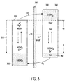
- FIG. 3 A schematic representation of a NiCd battery is shown in Fig. 3.
- the battery comprises a nickel electrode 300 and a cadmium-electrode 310 which are electrically insulated from each other by a separator 320.
- both separator and electrodes are impregnated with a concentrated alkaline solution (not shown).
- the electrochemically active species involved in the energy storage reactions are indicated in Fig. 3.
- nickelhydroxide (Ni(OH) 2 ) is oxidized to nickeloxyhydroxide (NiOOH) and cadmiumhydroxide (Cd(OH) 2 ) is reduced to metallic cadmium (Cd).
- the nominal storage capacity 330 of the battery is indicated by the white areas of both electrodes 300 and 310.
- the model used by the battery management system 100 includes at least one representation of the main electrochemical storage reaction.
- the basic electrochemical charge transfer reactions in its most simplified form are as follows: During charging divalent Ni II is oxidized into the trivalent Ni III state and Cd(OH) 2 is reduced to metallic Cd. The reverse reactions take place during discharging.
- the battery is designed in a very specific way, in particular to prevent gas pressure build-up within the batteries during overcharging and overdischarging. The various side-reactions taking place under these conditions will be discussed below.
- the Cd-electrode 310 comprises an overcharge reserve 340 in the form of an excess amount of Cd(OH) 2 , making the Ni-electrode the capacity determining electrode in a NiCd cell.
- overcharge reserve 340 in the form of an excess amount of Cd(OH) 2 , making the Ni-electrode the capacity determining electrode in a NiCd cell.
- an overdischarge reserve 350 in the form of a significant amount of Cd(OH) 2 is added to the Ni-electrode and, to a lesser extent, some metallic Cd is added to the Cd-electrode.
- the model used by the battery management system 100 also includes a representation of the electrochemical side reaction involving gas, such as for a NiCd battery given by reactions (3) and (4).
- the model used by the battery management system 100 additionally or alternatively also includes a representation of the electrochemical side reaction involving the overdischarge reserve 350, which for NiCd batteries may be formed by Cd(OH) 2 at the Ni-electrode and additional Cd at the Cd-electrode, and involves reaction (2).
- the electrochemical and physical processes occurring in a sealed rechargeable NiCd battery can be described by a set of mathematical equations. For each of these processes an equivalent electronic circuit element can be designated, which behaves according to the corresponding mathematical equation.
- a battery model can be created, in which the individual processes as well as the relations between the processes can be modelled.
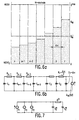
- FIG. 5 An electronic network model for a sealed rechargeable NiCd battery is shown in Fig. 5 with a main electrical circuit (Fig. 5a) and an auxiliary circuit (Fig. 5b) to calculate the partial oxygen pressure and oxygen reaction equilibrium potential.
- the three main parts of the NiCd battery can be distinguished in the form of a nickel electrode model 500, an electrolyte model 520 and a cadmium electrode model 530.
- the nickel electrode model 500 comprises a parallel construction of three sub-models 502, 504 and 506, each modelling a respective electrochemical reaction: the nickel main charge/discharge reaction, the oxygen overcharge reaction and cadmium overdischarge reaction.
- Each electrochemical reaction is modelled by a respective variable capacitor 508, 510, 512, in which chemical energy can be stored, in series with a respective block 514, 516, and 518 of two anti-parallel diodes.
- the anti-parallel diodes describe the kinetics of the oxidation and reduction reactions.
- the voltage across the variable capacitor equals the equilibrium potential of the reaction considered, whereas the voltage across the anti-parallel diodes represents the reaction overpotential.
- the charge separation effect taking place at the electrode surface when the electrode is immersed in the electrolyte is modelled by a double layer capacitor C dl / Ni 519 in parallel to the blocks 502, 504, and 506, which also include the reaction diodes.
- the ohmic material resistance is accounted for by the resistor R s / Ni 501.
- the electrolyte model 520 comprises an ohmic resistor R e 522.
- the model 530 of the cadmium electrode is modelled in an analogue manner to the nickel electrode.
- the model 530 comprises a sub-model 532 for the cadmium main charge/discharge reaction and a sub-model 534 for the oxygen side reaction.
- the electrochemical reactions are modelled by a respective variable capacitor 536 and 538, in which chemical energy can be stored, in series with a respective block 540 and 542 of two anti-parallel diodes.
- the model 530 also comprises a sub-model with the double layer capacitance C dl / Cd 544 in parallel to the blocks 532 and 534 for modelling the charge separation effect taking place at the electrode surface when the electrode is immersed in the electrolyte.
- the ohmic material resistance is accounted for by the resistor R s / Cd 546.
- ohmic resistance of the electrodes and electrolyte represented by 501, 522 and 546
- the main electrochemical storage reaction represented by the sub-models 502 and 532.
- charge separation effect at the electrode surfaces is represented.
- the side reaction involving gas is represented in the model.
- the gas side reaction relating to overcharging may be included, which is represented by the diodes 560 and 562 and does not require the diodes 564 and 566.
- the overdischarge reaction represented by 506 and 532 (for the excess cadmium) is also included.
- the diodes 564 and 566 representing the aspect of the gas side reaction relating to overdischarging, are included. It will be appreciated that this extension may be in addition to or replacing the overcharge reaction involving gas.
- the electrical double layer capacitance can in its simplest form be modelled by a flat plate capacitor, as indicated by C dl / Ni 519 in Fig. 5a.
- E e Ni ( t ) E 0 NiOOH / Ni ( OH ) 2 + RT nF ln a NiOOH ( t ) a H 2 O ( t ) a Ni ( OH ) 2 ( t ) a OH - ( t ) where a ( t ) refers to the activities under equilibrium conditions.
- the standard potential is a temperature dependent quantity, which can be represented by: where the temperature coefficient of redox system i (in this case: Ni) in [VK -1 ], is related to the entropy change according to
- I 0 Ni ( t ) nFA Ni k 0 Ni a a NiOOH ( t ) a 1- a Ni ( OH ) 2 ( t ) a a H 2 O ( t ) a 1- a OH - ( t ) Combining eqns.
- the overpotential consists of two contributions, the charge transfer overvoltage and the diffusion overvoltage.
- Q Ni the charge (Q Ni ) rather than in terms of activities.
- the kinetics of the charge and discharge reactions are modelled by the two anti-parallel diodes 550 and 552 in Fig. 5a.
- the upper diode 550 represents the oxidation reaction according to the first term on the right-hand side in eq. (21), whereas the reduction reaction is represented by the lower diode 552 in accordance with the second term in eq. (21).
- the voltage across these diodes corresponds to the overpotential for the Ni reaction.
- the equilibrium potential of the Ni electrode is state-of-charge dependent, in accordance with the Nernst equation (20), and can be recognised in Fig. 5a on the voltage across the variable capacitor C Ni 508.
- the state-of-charge of the Ni electrode surface determines the kinetics to a large extent.
- the model used by the battery management system also includes a representation for modelling ion transport in an electrode.
- the battery management system calculates the state of the ion transport and the influence on the main electrochemical storage reaction and/or the electrochemical side reaction involving the overdischarge reserve. For a NiCd battery this is achieved by modelling the solid state proton diffusion, which plays an important role in these kinetics. As a result of charging and discharging a proton concentration gradient will be built up, simultaneously changing Q Ni at the electrode surface.
- the solid state diffusion problem can be solved using Fick's laws of diffusion with the appropriate boundary conditions.
- the difference between the current flowing into and out of each element is given by the currents I j , which flow into the diffusion capacitors.
- the charge on each C j represents the state-of-charge of the corresponding electrode element.
- the charge on the first capacitor (C 1 ) in the diffusion network of Fig 6b corresponds to surface charge Q Ni (0,t) and is used for the calculation of ⁇ Ni in eq (21).
- Q N i is obtained from the sum of all charges on the capacitors in the diffusion network where Q i can be obtained by integrating eq. (31) over time.
- the following table summarises the analogy between electrical and electrochemical variables.
- the cadmium electrode is modelled as a heterogeneous system composed of two separate phases, the metallic cadmium and an oxide layer consisting of Cd(OH) 2 .
- Cadmium oxidation and the reduction of the oxide film is considered to occur according to a dissolution/precipitation mechanism in which the electrochemical charge transfer reaction is preceded or followed by a chemical dissolution or precipitation reaction.
- This reaction sequence can be represented by the chemical step: followed by the charge transfer:
- the electrochemical reaction rate is assumed to be determined by combined charge transfer and mass transfer of the OH - and Cd(OH) 2- / 4 species. Furthermore, it is assumed that charge transfer takes place only at the metallic cadmium surface, since the Cd(OH) 2 layer is a poor conductor.
- the general current-voltage relationships for the partial oxidation current I a / Cd and reduction current I c / Cd in this case are given by: and where A Cd denotes the metallic Cd surface area, Q Cd the state-of-charge of the cadmium electrode, k 0 / Cd the potential independent standard heterogeneous rate constant and E Cd the cadmium electrode potential.
- the activities a OH - (0, t ) and a Cd ( OH ) 2- 4 (0, t ) refer to the activities of the OH- and Cd(OH) 4 2- species at the electrode/electrolyte interface, respectively.
- E e Cd E 0 Cd / Cd ( OH ) 2 + RT nF ln a CdOH 2- 4 a Cd . a 4 OH -
- I k I d + I k
- I k the limiting kinetically controlled current given by The solution for I a / Cd is identical to eq. (39) since the mass transport problem during oxidation and reduction is symmetrical. From eq. (39-41) it is clear that A Cd is an important parameter for the kinetics of the Cd electrode. Evidently, A Cd is dependent on the state-of-charge and a mathematical description of this process is therefore desired.
- a metallic cadmium phase is formed at the cadmium and the nickel electrode, respectively.
- This new phase starts with the formation of single metallic nuclei. These grow further to form small metallic particles, which eventually coalesce to form a surface coating. It is assumed that the nuclei are formed instantaneously and are hemispherical.
- V (0) corresponds to the volume of the deposit at the time t 0 . This consists of both the volume of the initial amount of material present at the electrode and the volume of the metallic clusters formed during the nucleation stage.
- the integral term in eq. (42) is equivalent to the amount of charge, Q(t), formed during the growth of the assembly of metallic clusters. From eq. (42) it follows that the extended surface is given by:
- a Cd A max Cd (1 - e - ⁇ ex ) where A max / Cd refers to the maximum surface area of the cadmium electrode.
- I 0 O 2 ( t ) nFA j k 0 O 2 ⁇ l a ⁇ O 2 ( t ) a 2 ⁇ H 2 O a 4-(1- ⁇ ) OH -
- k 0 / O 2 ⁇ j and A j refer to the standard heterogeneous rate constant and the electrode surface area, respectively, at either the nickel electrode (during charging) or cadmium electrode (during overdischarging).
- the activities refer to the activities at the electrode/electrolyte interface.
- the activities of H 2 O and OH - are assumed to be time-independent.
- E e O 2 ( t ) E o O 2 / OH - + RT nF ln a O 2 ( t )
- a H 2 O and a OH - are included in E 0 / O 2 / OH - since it is assumed that they remain constant.
- I c O 2 ( t ) I k ( t ) .I d ( t ) I k ( t ) + I d ( t )
- I k ( t ) I 0, O 2 ( t ) exp ⁇ -(1 - ⁇ ) nF RT ⁇ rec ( t ) ⁇
- ⁇ rec is the overpotential for the oxygen recombination reaction at the Cd-electrode
- the processing means of the battery management system calculates a battery pressure based on a pressure model of a pressure development in the battery and calculates the behaviour of the oxygen evolution/recombination side reactions in dependence on the calculated battery pressure.
- the network also comprises an auxiliary circuit, as illustrated in Fig.
- dp O 2 dt - RT nFV g ( I a O 2 - I c O 2 )
- the amount of oxygen produced or consumed is determined by the difference between the oxidation and reduction current. If oxygen is produced at one electrode, it is recombined at the other electrode. The net amount of oxygen produced equals the difference between these two current sources and is integrated in capacitor C.
- Another function of the subcircuit of Fig. 5b is to determine the equilibrium voltage according to eq. (47). This equilibrium voltage is used for both oxygen reactions occurring at the nickel and at the cadmium electrodes and is copied to both oxygen paths for this purpose.
- Cd(OH) 2 is added to the nickel electrode to act as overdischarge reserve.
- the kinetics of this cadmium reaction are the same as those for the cadmium electrode and are thus given by eqns. (34) and (35).
- the determination of the concentration terms appearing in these equations, is described by eq. (39-41 ).
- the cadmium side reaction is modelled as a current path in parallel to the nickel main reaction illustrated by block 506 in Fig. 5a.
- the oxidation and reduction reactions are modelled by the two anti-parallel diodes 518.
- the equilibrium potential of the cadmium reaction is again given by the Nernst equation and is represented by the voltage across the variable capacitor 512.
- the battery temperature is modelled as depending on an internal heat flow generated in the battery.
- the battery temperature is determined by the net amount of heat ( Q b th ) present inside the battery and the heat capacitance ( C b th ) of the battery.
- the heat resistance ( R b th ) between the battery and its environment is modelled.
- the heat flow, ⁇ in , produced by the battery during operation is given by:
- the three terms of eq. (54) are, respectively, illustrated by P1, P2 and P3 of Fig. 7.
- the summation terms in eq. (54) refer to the heat production resulting from individual electrochemical reactions occurring inside the battery. Preferably, the heat production of all electrochemical reactions modelled by a chosen embodiment of the battery management system is incorporated.
- ⁇ S j the entropy change ( ⁇ S j ) resulting from each reaction with a number of n j electrons involved.
- the second term describes the power loss through each reaction-resistance and is given by the product of the partial current, I j , and the corresponding overvoltage, ⁇ j , of each electrochemical reaction.
- the entropy term can be both positive or negative, depending on the signs of I j and ⁇ S j .
- the other two terms are positive, because I j and ⁇ j have the same sign by definition.
- ⁇ in may be either positive or negative, depending on the magnitude of the three terms.
- the thermal heat resistance R b th is defined as 1/ ⁇ A. It is assumed that the heat resistance for conduction of heat inside the battery is so small that the temperature inside the battery may be considered uniform.
- T a a constant value is chosen, which preferably represent the ambient temperature of a typical environment in which the battery is used.
- T a a measured ambient temperature is used.
- the network model can easily be extended to more complex systems. For example, several heat sources and/or sinks with different origin can easily be added, resulting in a more complex thermal behaviour.
- model can easily be applied to types of batteries other than NiCd, such as Li-ion, Li-polymer and NiMH. Furthermore, the model can easily be extended, by including further sub-models, such as:
- the battery model can be used in a battery management system, which may be incorporated in an encompassing product, such as a smart battery or a battery charger.
- the model may also be used in a simulation tool, such as PSTAR.
- a simulation tool can, for instance, be used for:
- the battery simulator is used to simulate characteristics of the battery, based on input parameters which represent a physical quantity of a battery. Iteratively the input parameters can be adjusted, wheer for each set of input parameters it is checked whether a battery design based on the then selected design input parameters provides the required result.
- An example of a design parameter which can be chosen is the particle size of the electrode material, which in turn contributes to the surface area of the electrode and, as such, influences the charge transfer kinetics. If the simulation shows that the calculated characteristic(s) meet a predetermined criterion (e.g. the supplied current is sufficient for a given duration of stand-by power consumption and full power consumption), the battery is produced based on the design parameters which gave the desired result.
- the selected parameter values may directly or indirectly determine aspects such as:
- the parameters may determine the chemical composition of the battery (e.g. which battery materials should be used) and/or physical characteristics of the battery materials or the battery (e.g. determining that raw electrode materials should be preprocessed in order to enlarge the surface area).
- the battery management system 100 of Fig. 2 controls the battery charger 200 by maintaining the battery temperature substantially at a predetermined temperature curve.
- the battery temperature is maintained at a constant temperature of, for instance, 30°C.
- the battery temperature is maintained at a predetermined offset, for instance 10°C, related to the ambient temperature. It will be appreciated that also more advanced curves may be used, which allow the battery to be charged more fully or quicker.
- the described simulation tool can efficiently be used to design an optimum temperature curve for a specific application and operating environment.
- any conventional control loop may be used to control the battery charger 200 in such a way that the battery temperature substantially matches the predetermined temperature curve.
- the current or voltage level supplied by the battery charger 200 may be controlled by the control loop.
- the battery charger 200 may use a pulsed-voltage or pulsed-current charging scheme, where the control loop controls, for instance, the pulse duration and/or pulse shape. Obviously also suitable combinations of the charging schemes may be used.
- the battery management system 100 uses the calculated battery temperature for accurately controlling the battery charger 200. It will be appreciated that in a simple embodiment, the battery management system 100 may use a measured battery temperature to control the battery charger 200.
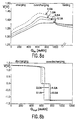
- Figures 8, 9 and 10 illustrate the simulated charge behaviour of a NiCd battery versus voltage (Fig. 8), pressure (Fig. 9), and temperature (Fig. 10) for constant current charging and discharging.
- the simulation results were achieved using the described model with parameter values given in the Appendix and a constant ambient temperature of 25°C.
- the horizontal axis in the figures denotes the applied ( Q in) or the withdrawn (Q out ) charge, which is calculated from the product of time and current. It will be appreciated that shapes of the curves shown in the figures with simulation results provide a good match with the real behaviour of a battery.
- Fig. 8a and Fig. 8b The influence of the charge/discharge current on the battery voltage during charging and discharging is depicted in Fig. 8a and Fig. 8b, respectively.
- the battery voltage of the charging curves shown in Fig. 8a starts at a value of about 1.3V and then gradually increases. Near the end of charging the voltage rises more steeply and reaches a maximum value, after which, in the overcharging region, a voltage decline can be distinguished, especially for larger currents.
- This - ⁇ V effect is more pronounced at higher currents because in those cases the temperature rise during overcharging is higher, as shown in Fig. 10a.
- true equilibrium can never be reached in a NiCd battery, due to the thermodynamic instability of the nickel electrode.
- Fig. 8a shows that the battery voltage increases at higher charging currents due to the higher potential drop. This is caused by:
- Fig. 8b shows the battery voltage development during discharging as a function of the discharge current. Again, the battery voltage depends strongly on the applied discharge current. The battery voltage remains relatively constant. However, towards the end of discharging the voltage drops sharply to about 0V, which is the value of the first plateau associated with overdischarging. In this stage of the discharging process metallic cadmium is oxidized at the cadmium electrode and the overdischarge reserve consisting of Cd(OH) 2 in the nickel electrode, is reduced, as also illustrated in Fig. 3.
- Fig. 9a shows the corresponding pressure development during charging.
- the pressure rise occurs earlier due to the lower charge efficiency at higher charging currents.
- the pressure levels off to reach a maximum, which is higher for higher currents.
- the steep temperature rise during overcharging may lead to a situation where, especially for high charging currents, the oxygen recombination reaction rate exceeds the oxygen evolution reaction rate. This causes the pressure during overcharging to decrease again.
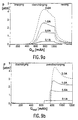
- Fig. 10a The temperature development during charging is shown in Fig. 10a. As is to be expected, the temperature becomes higher at higher currents. The strongest temperature rise occurs when the pressure starts to level off. This is due to the large heat contribution of the oxygen recombination reaction, which occurs at an overpotential of 1.2V (refer eq. (54)).
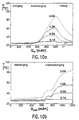
- Figures 9b and 10b show the pressure and temperature development during discharging, respectively.
- the cell voltage reverses earlier as illustrated in Fig. 8b. Therefore, the pressure rises earlier in Fig. 9b.
- the pressure reaches a plateau value due to the oxygen recombination reaction taking place at the nickel electrode. Again, at higher discharge currents a pressure decrease can be noticed, caused by the temperature dependence of the oxygen recombination reaction.
- the ambient temperature has a strong influence on the battery performance, since the temperature is an important parameter which appears in practically all mathematical equations describing the battery related processes. Modelling of the influence of the ambient temperature can be performed with the network of Fig. 7. The ambient temperature can simply be regulated by adjusting the voltage across the capacitor C a th . Due to the coupling between the sub-circuits representing the thermal, electrical, concentration and pressure domains, the influence of the ambient temperature is immediately seen in the simulated battery characteristics.
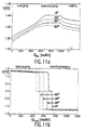
- Figures 11, 12 and 13 illustrate the simulated charge behaviour of a NiCd battery versus voltage (Fig. 11), pressure (Fig. 12), and state of charge (Fig. 13) as a function of the ambient temperature. The simulation results were achieved using the described model with parameter values given in the Appendix and a charge/discharge current of 0.1A.
- Fig. 11a and 11b show the influence of the ambient temperature on the simulated charge and discharge characteristics.
- the battery voltage is lower at higher temperatures. This effect is caused, on the one hand, by decreasing equilibrium potentials (voltage across variable capacitors in Fig 5a) of both the nickel and cadmium reactions at higher temperatures due to their negative temperature coefficients and, on the other hand, by decreasing reaction overpotentials due to the improved kinetics and mass transport (lower voltage across diodes in Fig. 5a).
- the temperature behaviour of the battery voltage characteristics reverses as illustrated in Fig. 11b.
- Fig. 11a shows that the steep voltage rise disappears at higher temperatures. This is an indication that the charge efficiency decreases at higher temperatures and that the competition between the nickel and oxygen evolution reaction becomes more severe.
- the lower charge efficiency at elevated temperatures is due to the improved kinetics of the oxygen evolution reaction at high temperatures.
- Fig. 12a where the cell pressure starts to increase already in an early stage of the charging process at higher temperatures.
- the pressure plateau value is lower at higher temperatures, however, due to the better oxygen recombination reaction kinetics at higher temperatures.
- overdischarging the pressure increases earlier at higher temperatures as shown in Fig. 12b. The reason for this is that, due to the lower charge efficiency, Q Ni before discharging is lower for higher temperatures and therefore the overdischarged state is reached earlier.
- both the nickel and cadmium electrodes are slowly discharged.
- the nickel electrode shows selfdischarge behaviour due to its thermodynamic instability with respect to the oxygen evolution reaction, as a result of which the NiOOH species is continuously reduced while the electrolyte species (OH - ) is oxidized.
- the cadmium electrode is selfdischarged as a result of the gaseous oxygen formed at the nickel electrode, which continues to recombine according to eq. (2) and (4). Since at the nickel electrode oxygen is continuously formed, selfdischarge of the cadmium electrode perpetuates. The selfdischarge behaviour is thus the result of two separate loop currents, which can also be recognised in the electronic network of Fig. 5a.
- the simulated selfdischarge behaviour is shown in Fig. 14 at different ambient temperatures. This figure shows that the battery selfdischarges more significantly at higher temperatures. This is a result of the improved kinetics of both the oxygen evolution and recombination reaction at higher temperatures.
Landscapes
- Physics & Mathematics (AREA)
- General Physics & Mathematics (AREA)
- Engineering & Computer Science (AREA)
- Manufacturing & Machinery (AREA)
- Chemical & Material Sciences (AREA)
- Chemical Kinetics & Catalysis (AREA)
- Electrochemistry (AREA)
- General Chemical & Material Sciences (AREA)
- Secondary Cells (AREA)
Claims (15)
- Système de gestion de batterie comprenant :caractérisé en ce que le moyen de traitement comprend un moyen pourun moyen d'entrée pour recevoir des signaux d'entrée représentatifs d'une quantité physique d'une batterie, etun moyen de traitement pour calculer au moins une quantité physique de la batterie au moins partiellement sur la base des signaux d'entrée et d'une température de batterie, et pour générer un signal de sortie dérivé de la quantité physique calculée ;calculer la quantité physique sur la base d'un modèle électrochimique/physique de la batterie ; le modèle comprenant au moins une représentation d'une réaction d'accumulation électrochimique principale ;calculer la température de batterie sur la base d'un modèle de température d'un développement de température dans la batterie et pour calculer le comportement de la représentation en fonction de la température de batterie calculée, etdériver un signal de sortie au moins partiellement d'un état de la représentation.
- Système de gestion de batterie suivant la revendication 1, caractérisé en ce que la température de batterie est modélisée en fonction d'un flux de chaleur interne généré dans la batterie, où le flux de chaleur interne dépend d'au moins un des éléments suivants : un changement d'entropie de la réaction d'accumulation électrochimique principale à l'intérieur de la batterie, des pertes d'énergie par résistance au transfert de charge dans une réaction électrochimique et des pertes d'énergie par résistance ohmique interne d'une électrode et/ou d'un électrolyte.
- Système de gestion de batterie suivant la revendication 1 ou 2, caractérisé en ce que le moyen d'entrée comprend une entrée pour recevoir un signal représentatif d'une température ambiante et en ce que la température de la batterie est modélisée en fonction d'un flux de chaleur entre la batterie et un environnement de la batterie.
- Système de gestion de batterie suivant la revendication 1, 2 ou 3, caractérisé en ce qu'au moins une électrode comprend une réserve de décharge excessive ; en ce que le modèle comprend une deuxième représentation d'une réaction électrochimique secondaire impliquant la réserve de décharge excessive, et en ce que le moyen de traitement est conçu pour calculer un état de la deuxième représentation en fonction de la température de batterie calculée et pour dériver le signal de commande au moins partiellement d'un état de la deuxième représentation.
- Système de gestion de batterie suivant les revendications 2 et 4, caractérisé en ce que la température de batterie est modélisée en fonction d'un changement d'entropie de la réaction électrochimique secondaire impliquant la réserve de décharge excessive.
- Système de gestion de batterie suivant la revendication 1, 2, 3, 4 ou 5, caractérisé en ce que la batterie est d'un type hermétique ; en ce que le modèle comprend une troisième représentation d'une réaction électrochimique secondaire impliquant un gaz, et en ce que le moyen de traitement comprend un moyen pour calculer un état de la troisième représentation en fonction de la température de batterie calculée et pour dériver le signal de sortie au moins partiellement d'un état de la troisième représentation.
- Système de gestion de batterie suivant les revendications 2 et 6, caractérisé en ce que la température de batterie est modélisée en fonction d'un changement d'entropie de la réaction électrochimique secondaire impliquant un gaz.
- Système de gestion de batterie suivant la revendication 6 ou 7, caractérisé en ce que le moyen de traitement comprend un moyen pour calculer une pression de batterie sur la base d'un modèle de pression d'un développement de pression dans la batterie pour les signaux d'entrée reçus et pour calculer le comportement de la troisième représentation en fonction de la pression de batterie calculée.
- Système de gestion de batterie suivant l'une quelconque des revendications précédentes, caractérisé en ce que le modèle comprend une quatrième représentation pour modéliser le transport d'ions dans une électrode et/ou un électrolyte, et en ce que le moyen de traitement comprend un moyen pour calculer un état de la quatrième représentation et une influence de la quatrième représentation sur la première et/ou deuxième représentations.
- Système de gestion de batterie suivant l'une quelconque des revendications précédentes, dans lequel le signal de sortie commande un chargeur de batterie, caractérisé en ce que le moyen de traitement comprend un moyen pour commander la charge de la batterie en maintenant une température de batterie sensiblement au niveau d'une courbe de température prédéterminée.
- Batterie intelligente comprenant :une batterie ;un système de gestion de batterie ;un moyen de mesure pour mesurer au moins une quantité physique de la batterie ; dans laquelle le moyen de mesure est connecté à un moyen d'entrée du système de gestion de batterie, etun moyen d'information/commande pour présenter des informations concernant la quantité physique de la batterie et/ou commander la charge/décharge de la batterie en réponse au signal de sortie du système de gestion de batterie, caractérisée en ce que le système de gestion de batterie est un système suivant l'une quelconque des revendications précédentes.
- Chargeur/déchargeur de batterie comprenant :un système de gestion de batterie ;un moyen de mesure pour mesurer au moins une quantité physique de la batterie ; dans laquelle le moyen de mesure est connecté à un moyen d'entrée du système de gestion de batterie, etun moyen de commande pour commander la charge et/ou la décharge de la batterie en réponse au signal de sortie du système de gestion de batterie, caractérisé en ce que le système de gestion de batterie est un système suivant l'une quelconque des revendications 1 à 11.
- Simulateur de batterie comprenant :caractérisé en ce que le moyen de traitement comprend un moyen pourun moyen d'entrée pour recevoir une valeur d'entrée d'au moins un paramètre représentatif d'une quantité physique d'une batterie, etun moyen de traitement pour calculer au moins une caractéristique d'une quantité physique de la batterie au moins partiellement sur la base de la valeur d'entrée et d'une température de batterie, et pour générer une caractéristique de sortie dérivée de la caractéristique calculée de la quantité physique ;calculer la température de batterie sur la base d'un modèle de température d'un développement de température dans la batterie ;calculer la caractéristique de la quantité physique sur la base d'un modèle électrochimique/physique de la batterie ; le modèle comprenant au moins une représentation d'une réaction d'accumulation électrochimique principale, dont le comportement dépend de la température de batterie calculée, etdériver la caractéristique de sortie au moins partiellement d'un état de la représentation de la réaction d'accumulation électrochimique principale.
- Procédé permettant de simuler un comportement d'une batterie, le procédé comprenant les étapes suivantes :caractérisé en ce que le procédé comprend les étapes suivantes :la réception d'une valeur d'entrée d'au moins un paramètre représentatif d'une quantité physique de la batterie ;le calcul d'au moins une caractéristique d'une quantité physique de la batterie au moins partiellement sur la base de la valeur d'entrée et d'une température de batterie ;la génération d'une caractéristique de sortie dérivée de la caractéristique calculée de la quantité physique ;le calcul de la température de batterie sur la base d'un modèle de température d'un développement de température dans la batterie ;le calcul de la caractéristique de la quantité physique sur la base d'un modèle électrochimique/physique de la batterie, le modèle comprenant au moins une représentation d'une réaction d'accumulation électrochimique principale, dont le comportement dépend de la température de batterie calculée, etla dérivation de la caractéristique de sortie au moins partiellement d'un état de la représentation de la réaction d'accumulation électrochimique principale.
- Procédé permettant de produire une batterie, comprenant les étapes suivantes :la simulation d'une caractéristique de la batterie, par
itérativement :jusqu'à ce que la caractéristique calculée satisfasse un critère prédéterminé, et la production de la batterie à partir de matériaux de batterie en sélectionnant et/ou en adaptant une composition chimique et/ou une caractéristique physique des matériaux de batterie en fonction des valeurs paramétriques sélectionnées en dernier dans l'itération.la sélection d'une valeur pour au moins un paramètre représentatif d'une quantité physique de la batterie ;le calcul d'au moins une caractéristique d'une quantité physique de la batterie au moins partiellement sur la base de la valeur paramétrique et d'une température de batterie, et :le calcul de la température de batterie sur la base d'un modèle de température d'un développement de température dans la batterie, etle calcul de la caractéristique de la quantité physique de la batterie sur la base d'un modèle électrochimique/physique de la batterie ; le modèle incluant au moins une représentation d'une réaction d'accumulation électrochimique principale dont le comportement dépend de la température de batterie calculée ; la caractéristique calculée étant au moins partiellement dérivée d'un état de la représentation de la réaction d'accumulation électrochimique principale ;
Priority Applications (1)
| Application Number | Priority Date | Filing Date | Title |
|---|---|---|---|
| EP97909545A EP0880710B1 (fr) | 1996-11-21 | 1997-11-10 | Systeme de gestion de batterie et simulateur de batterie |
Applications Claiming Priority (4)
| Application Number | Priority Date | Filing Date | Title |
|---|---|---|---|
| EP96203228 | 1996-11-21 | ||
| EP96203228 | 1996-11-21 | ||
| EP97909545A EP0880710B1 (fr) | 1996-11-21 | 1997-11-10 | Systeme de gestion de batterie et simulateur de batterie |
| PCT/IB1997/001418 WO1998022830A2 (fr) | 1996-11-21 | 1997-11-10 | Systeme de gestion de batterie et simulateur de batterie |
Publications (2)
| Publication Number | Publication Date |
|---|---|
| EP0880710A2 EP0880710A2 (fr) | 1998-12-02 |
| EP0880710B1 true EP0880710B1 (fr) | 2004-08-25 |
Family
ID=8224595
Family Applications (1)
| Application Number | Title | Priority Date | Filing Date |
|---|---|---|---|
| EP97909545A Expired - Lifetime EP0880710B1 (fr) | 1996-11-21 | 1997-11-10 | Systeme de gestion de batterie et simulateur de batterie |
Country Status (5)
| Country | Link |
|---|---|
| US (1) | US6016047A (fr) |
| EP (1) | EP0880710B1 (fr) |
| JP (1) | JP2000504477A (fr) |
| DE (1) | DE69730413T2 (fr) |
| WO (1) | WO1998022830A2 (fr) |
Cited By (5)
| Publication number | Priority date | Publication date | Assignee | Title |
|---|---|---|---|---|
| US8487628B2 (en) | 2008-03-28 | 2013-07-16 | IFP Energies Nouvelles | System for smart management of an electrochemical battery |
| US8548762B2 (en) | 2009-09-02 | 2013-10-01 | IFP Energies Nouvelles | Method of estimating the non-measurable characteristics of an electrochemical system |
| US8849598B2 (en) | 2010-09-27 | 2014-09-30 | IFP Energies Nouvelles | In-situ battery diagnosis method using electrochemical impedance spectroscopy |
| TWI463721B (zh) * | 2013-02-08 | 2014-12-01 | Simplo Technology Co Ltd | 具多模式之電池管理系統及其切換方法 |
| US8984944B2 (en) | 2011-09-30 | 2015-03-24 | IFP Energies Nouvelles | Method and system for diagnosis of the internal state of a battery through acoustic emission |
Families Citing this family (237)
| Publication number | Priority date | Publication date | Assignee | Title |
|---|---|---|---|---|
| US6566883B1 (en) * | 1999-11-01 | 2003-05-20 | Midtronics, Inc. | Electronic battery tester |
| US7706991B2 (en) * | 1996-07-29 | 2010-04-27 | Midtronics, Inc. | Alternator tester |
| US7003410B2 (en) * | 1996-07-29 | 2006-02-21 | Midtronics, Inc. | Electronic battery tester with relative test output |
| US8872517B2 (en) | 1996-07-29 | 2014-10-28 | Midtronics, Inc. | Electronic battery tester with battery age input |
| US8198900B2 (en) * | 1996-07-29 | 2012-06-12 | Midtronics, Inc. | Automotive battery charging system tester |
| US7246015B2 (en) * | 1996-07-29 | 2007-07-17 | Midtronics, Inc. | Alternator tester |
| US6850037B2 (en) | 1997-11-03 | 2005-02-01 | Midtronics, Inc. | In-vehicle battery monitor |
| US6871151B2 (en) * | 1997-11-03 | 2005-03-22 | Midtronics, Inc. | Electronic battery tester with network communication |
| US7705602B2 (en) | 1997-11-03 | 2010-04-27 | Midtronics, Inc. | Automotive vehicle electrical system diagnostic device |
| US7126341B2 (en) * | 1997-11-03 | 2006-10-24 | Midtronics, Inc. | Automotive vehicle electrical system diagnostic device |
| US7774151B2 (en) * | 1997-11-03 | 2010-08-10 | Midtronics, Inc. | Wireless battery monitor |
| US7688074B2 (en) * | 1997-11-03 | 2010-03-30 | Midtronics, Inc. | Energy management system for automotive vehicle |
| US8958998B2 (en) | 1997-11-03 | 2015-02-17 | Midtronics, Inc. | Electronic battery tester with network communication |
| GB9804684D0 (en) * | 1998-03-05 | 1998-04-29 | Lucas Ind Plc | Method and apparatus for estimating the charge in a battery |
| US6218806B1 (en) * | 1998-06-03 | 2001-04-17 | Black & Decker Inc. | Method and apparatus for obtaining product use information |
| US6157173A (en) * | 1999-01-27 | 2000-12-05 | Sony Corporation | Circuit and method for sharing current between a portable device and a battery charger |
| US6326767B1 (en) | 1999-03-30 | 2001-12-04 | Shoot The Moon Products Ii, Llc | Rechargeable battery pack charging system with redundant safety systems |
| US7505856B2 (en) * | 1999-04-08 | 2009-03-17 | Midtronics, Inc. | Battery test module |
| US6124701A (en) * | 1999-06-22 | 2000-09-26 | Lucent Technologies, Inc. | System and method for determining battery condition and telecommunications equipment incorporating the same |
| WO2001015023A1 (fr) * | 1999-08-19 | 2001-03-01 | Motorola Inc. | Modeles de batteries modulaires pour simulateurs de circuits electroniques |
| US6307352B1 (en) * | 1999-10-19 | 2001-10-23 | Enrev Corporation | High energy charge and depolarization pulse conditioner for an enhanced-reliability lead-acid battery charger |
| DE19959019A1 (de) * | 1999-12-08 | 2001-06-13 | Bosch Gmbh Robert | Verfahren zur Zustandserkennung eines Energiespeichers |
| KR100342716B1 (ko) * | 1999-12-18 | 2002-07-04 | 서평원 | 충전 중 배터리 게이징 장치 |
| US6759849B2 (en) * | 2000-03-27 | 2004-07-06 | Kevin I. Bertness | Battery tester configured to receive a removable digital module |
| US7398176B2 (en) | 2000-03-27 | 2008-07-08 | Midtronics, Inc. | Battery testers with secondary functionality |
| US7598744B2 (en) * | 2000-03-27 | 2009-10-06 | Midtronics, Inc. | Scan tool for electronic battery tester |
| US7598743B2 (en) * | 2000-03-27 | 2009-10-06 | Midtronics, Inc. | Battery maintenance device having databus connection |
| US8513949B2 (en) | 2000-03-27 | 2013-08-20 | Midtronics, Inc. | Electronic battery tester or charger with databus connection |
| US7446536B2 (en) * | 2000-03-27 | 2008-11-04 | Midtronics, Inc. | Scan tool for electronic battery tester |
| US6291968B1 (en) | 2000-05-08 | 2001-09-18 | Lear Corporation | System for automatically charging the battery of a remote transmitter for use in a vehicle security system |
| US20020169620A1 (en) * | 2001-03-29 | 2002-11-14 | Spotnitz Robert M. | Method of doing business: customer-driven design of a charge storage device |
| DE10121962A1 (de) * | 2001-05-05 | 2002-11-07 | Vb Autobatterie Gmbh | Energiemanagementsystem für ein elektrisches Kraftfahrzeugbordnetz |
| DE10126891A1 (de) * | 2001-06-01 | 2002-12-05 | Vb Autobatterie Gmbh | Verfahren zur Vorhersage der Belastbarkeit eines elektrochemischen Elementes |
| US6941234B2 (en) * | 2001-10-17 | 2005-09-06 | Midtronics, Inc. | Query based electronic battery tester |
| FI114048B (fi) * | 2001-12-03 | 2004-07-30 | Teknillinen Korkeakoulu | Menetelmä ja laitteisto akkujen kuvaamiseksi ohjelmallisilla mittareilla |
| KR20030046076A (ko) * | 2001-12-05 | 2003-06-12 | 에스케이텔레텍주식회사 | 배터리의 충전 상태를 표시하기 위한 충전기 |
| US6727708B1 (en) | 2001-12-06 | 2004-04-27 | Johnson Controls Technology Company | Battery monitoring system |
| DE10210516B4 (de) | 2002-03-09 | 2004-02-26 | Vb Autobatterie Gmbh | Verfahren und Einrichtung zum Ermitteln der Funktionsfähigkeit einer Speicherbatterie |
| DE10215071A1 (de) * | 2002-04-05 | 2003-10-30 | Vb Autobatterie Gmbh | Verfahren zur Bestimmung des Verschleißes eines elektrochemischen Energiespeichers sowie Energiespeicher |
| DE10224662C1 (de) * | 2002-06-03 | 2003-06-18 | Vb Autobatterie Gmbh | Ladezustandsanzeiger für eine Batterie |
| US20030236656A1 (en) * | 2002-06-21 | 2003-12-25 | Johnson Controls Technology Company | Battery characterization system |
| DE10231700B4 (de) * | 2002-07-13 | 2006-06-14 | Vb Autobatterie Gmbh & Co. Kgaa | Verfahren zur Ermittlung des Alterungszustandes einer Speicherbatterie hinsichtlich der entnehmbaren Ladungsmenge und Überwachungseinrichtung |
| DE10234032A1 (de) * | 2002-07-26 | 2004-02-05 | Vb Autobatterie Gmbh | Energiespeicher und Verfahren zur Ermittlung des Verschleißes eines elektrochemischen Energiespeichers |
| DE10236958B4 (de) * | 2002-08-13 | 2006-12-07 | Vb Autobatterie Gmbh & Co. Kgaa | Verfahren zur Ermittlung der entnehmbaren Ladungsmenge einer Speicherbatterie und Überwachungseinrichtung für eine Speicherbatterie |
| JP3725105B2 (ja) * | 2002-08-30 | 2005-12-07 | 株式会社東芝 | 二次電池の過放電防止回路及び二次電池の過放電防止法 |
| DE10240329B4 (de) * | 2002-08-31 | 2009-09-24 | Vb Autobatterie Gmbh & Co. Kgaa | Verfahren zur Ermittlung der einer vollgeladenen Speicherbatterie entnehmbaren Ladungsmenge einer Speicherbatterie und Überwachungseinrichtung für eine Speicherbatterie |
| DE10252760B4 (de) * | 2002-11-13 | 2009-07-02 | Vb Autobatterie Gmbh & Co. Kgaa | Verfahren zur Vorhersage des Innenwiderstands einer Speicherbatterie und Überwachungseinrichtung für Speicherbatterien |
| DE10253051B4 (de) | 2002-11-14 | 2005-12-22 | Vb Autobatterie Gmbh | Verfahren zur Ermittlung der Ladungsaufnahme einer Speicherbatterie |
| WO2004062010A1 (fr) * | 2002-12-31 | 2004-07-22 | Midtronics, Inc. | Appareil et procede pour predire le temps de decharge restant d'une batterie |
| US20040145352A1 (en) * | 2003-01-07 | 2004-07-29 | Chris Harrison | Method and apparatus for providing temperature-regulated battery charging |
| US7358701B2 (en) * | 2003-02-07 | 2008-04-15 | Field Robert B | Method and system for modeling energy transfer |
| DE10318494A1 (de) * | 2003-04-24 | 2004-11-11 | Bayerische Motoren Werke Ag | Energieversorgungssystem für ein Fahrzeug |
| US7408358B2 (en) * | 2003-06-16 | 2008-08-05 | Midtronics, Inc. | Electronic battery tester having a user interface to configure a printer |
| DE10335930B4 (de) | 2003-08-06 | 2007-08-16 | Vb Autobatterie Gmbh & Co. Kgaa | Verfahren zur Bestimmung des Zustands einer elektrochemischen Speicherbatterie |
| US9018958B2 (en) | 2003-09-05 | 2015-04-28 | Midtronics, Inc. | Method and apparatus for measuring a parameter of a vehicle electrical system |
| US9255955B2 (en) | 2003-09-05 | 2016-02-09 | Midtronics, Inc. | Method and apparatus for measuring a parameter of a vehicle electrical system |
| US8164343B2 (en) * | 2003-09-05 | 2012-04-24 | Midtronics, Inc. | Method and apparatus for measuring a parameter of a vehicle electrical system |
| US7154276B2 (en) * | 2003-09-05 | 2006-12-26 | Midtronics, Inc. | Method and apparatus for measuring a parameter of a vehicle electrical system |
| US7977914B2 (en) | 2003-10-08 | 2011-07-12 | Midtronics, Inc. | Battery maintenance tool with probe light |
| US7595643B2 (en) * | 2003-11-11 | 2009-09-29 | Midtronics, Inc. | Apparatus and method for simulating a battery tester with a fixed resistance load |
| US7321220B2 (en) * | 2003-11-20 | 2008-01-22 | Lg Chem, Ltd. | Method for calculating power capability of battery packs using advanced cell model predictive techniques |
| WO2005071021A1 (fr) * | 2004-01-16 | 2005-08-04 | Deft, Inc. | Revetements directs sur substrats |
| DE102004005478B4 (de) * | 2004-02-04 | 2010-01-21 | Vb Autobatterie Gmbh | Verfahren zur Bestimmung von Kenngrößen für elektrische Zustände einer Speicherbatterie und Überwachungseinrichtung hierzu |
| DE102004007904B4 (de) * | 2004-02-18 | 2008-07-03 | Vb Autobatterie Gmbh & Co. Kgaa | Verfahren zur Bestimmung mindestens einer Kenngröße für den Zustand einer elektrochemischen Speicherbatterie und Überwachungseinrichtung |
| US7598699B2 (en) * | 2004-02-20 | 2009-10-06 | Midtronics, Inc. | Replaceable clamp for electronic battery tester |
| US7777612B2 (en) * | 2004-04-13 | 2010-08-17 | Midtronics, Inc. | Theft prevention device for automotive vehicle service centers |
| US7119686B2 (en) * | 2004-04-13 | 2006-10-10 | Midtronics, Inc. | Theft prevention device for automotive vehicle service centers |
| US7642786B2 (en) | 2004-06-01 | 2010-01-05 | Midtronics, Inc. | Battery tester capable of identifying faulty battery post adapters |
| US20060001399A1 (en) * | 2004-07-02 | 2006-01-05 | Lembit Salasoo | High temperature battery system for hybrid locomotive and offhighway vehicles |
| US7772850B2 (en) * | 2004-07-12 | 2010-08-10 | Midtronics, Inc. | Wireless battery tester with information encryption means |
| US7106070B2 (en) * | 2004-07-22 | 2006-09-12 | Midtronics, Inc. | Broad-band low-inductance cables for making Kelvin connections to electrochemical cells and batteries |
| US20060038572A1 (en) * | 2004-08-20 | 2006-02-23 | Midtronics, Inc. | System for automatically gathering battery information for use during battery testing/charging |
| US8344685B2 (en) * | 2004-08-20 | 2013-01-01 | Midtronics, Inc. | System for automatically gathering battery information |
| US8436619B2 (en) * | 2004-08-20 | 2013-05-07 | Midtronics, Inc. | Integrated tag reader and environment sensor |
| US9496720B2 (en) | 2004-08-20 | 2016-11-15 | Midtronics, Inc. | System for automatically gathering battery information |
| US8442877B2 (en) * | 2004-08-20 | 2013-05-14 | Midtronics, Inc. | Simplification of inventory management |
| CN100401613C (zh) * | 2004-11-10 | 2008-07-09 | 环隆电气股份有限公司 | 智能电池模拟系统 |
| CN100399668C (zh) * | 2004-11-10 | 2008-07-02 | 环隆电气股份有限公司 | 智能电池模拟装置 |
| US7710119B2 (en) * | 2004-12-09 | 2010-05-04 | Midtronics, Inc. | Battery tester that calculates its own reference values |
| US7545146B2 (en) | 2004-12-09 | 2009-06-09 | Midtronics, Inc. | Apparatus and method for predicting battery capacity and fitness for service from a battery dynamic parameter and a recovery voltage differential |
| US20060132097A1 (en) * | 2004-12-21 | 2006-06-22 | Chi-Hao Chiang | Smart battery simulator |
| US20060132098A1 (en) * | 2004-12-21 | 2006-06-22 | Min-Hsiung Lin | Smart battery simulating system |
| GB0502274D0 (en) * | 2005-02-04 | 2005-03-09 | Xipower Ltd | Battery management system |
| US7498767B2 (en) * | 2005-02-16 | 2009-03-03 | Midtronics, Inc. | Centralized data storage of condition of a storage battery at its point of sale |
| US7197487B2 (en) * | 2005-03-16 | 2007-03-27 | Lg Chem, Ltd. | Apparatus and method for estimating battery state of charge |
| DE102005012999A1 (de) * | 2005-03-21 | 2006-09-28 | Siemens Ag | Verfahren zur Steuerung eines tragbaren elektronischen Geräts mit einer elektrischen Energiespeichereinrichtung |
| US8446127B2 (en) * | 2005-08-03 | 2013-05-21 | California Institute Of Technology | Methods for thermodynamic evaluation of battery state of health |
| US7723957B2 (en) * | 2005-11-30 | 2010-05-25 | Lg Chem, Ltd. | System, method, and article of manufacture for determining an estimated battery parameter vector |
| US7400115B2 (en) * | 2006-02-09 | 2008-07-15 | Lg Chem, Ltd. | System, method, and article of manufacture for determining an estimated combined battery state-parameter vector |
| DE102006017889A1 (de) * | 2006-04-13 | 2007-10-25 | Linde Material Handling Gmbh | Flurförderzeug mit einer Batterie und Verfahren zum Betrieb eines Flurförderzeugs mit einer Batterie |
| DE102006024798B3 (de) * | 2006-05-27 | 2007-03-22 | Vb Autobatterie Gmbh & Co. Kgaa | Ladezustandsanzeiger |
| US20070287623A1 (en) * | 2006-06-10 | 2007-12-13 | Carlson Daniel L | Compact dunnage converter |
| JP4697105B2 (ja) * | 2006-09-21 | 2011-06-08 | 横河電機株式会社 | 電池特性模擬装置 |
| US8054046B2 (en) * | 2006-12-06 | 2011-11-08 | GM Global Technology Operations LLC | Fast search algorithm for finding initial diffusion voltage in electro-chemical systems |
| GB2444511B (en) * | 2006-12-06 | 2008-10-22 | Iti Scotland Ltd | Battery Management System |
| US7646166B2 (en) * | 2006-12-06 | 2010-01-12 | Gm Global Technology Operations, Inc. | Method and apparatus for modeling diffusion in an electrochemical system |
| US7791348B2 (en) * | 2007-02-27 | 2010-09-07 | Midtronics, Inc. | Battery tester with promotion feature to promote use of the battery tester by providing the user with codes having redeemable value |
| US7808375B2 (en) | 2007-04-16 | 2010-10-05 | Midtronics, Inc. | Battery run down indicator |
| US9274157B2 (en) * | 2007-07-17 | 2016-03-01 | Midtronics, Inc. | Battery tester for electric vehicle |
| GB2463829B (en) * | 2007-07-17 | 2012-11-21 | Midtronics Inc | Battery tester for electric vehicle |
| US8203345B2 (en) * | 2007-12-06 | 2012-06-19 | Midtronics, Inc. | Storage battery and battery tester |
| US8628872B2 (en) * | 2008-01-18 | 2014-01-14 | Lg Chem, Ltd. | Battery cell assembly and method for assembling the battery cell assembly |
| US7994755B2 (en) | 2008-01-30 | 2011-08-09 | Lg Chem, Ltd. | System, method, and article of manufacture for determining an estimated battery cell module state |
| US7959476B2 (en) * | 2008-06-16 | 2011-06-14 | Midtronics, Inc. | Clamp for electrically coupling to a battery contact |
| US7945344B2 (en) * | 2008-06-20 | 2011-05-17 | SAKT13, Inc. | Computational method for design and manufacture of electrochemical systems |
| US9249502B2 (en) * | 2008-06-20 | 2016-02-02 | Sakti3, Inc. | Method for high volume manufacture of electrochemical cells using physical vapor deposition |
| US7883793B2 (en) * | 2008-06-30 | 2011-02-08 | Lg Chem, Ltd. | Battery module having battery cell assemblies with alignment-coupling features |
| US9759495B2 (en) * | 2008-06-30 | 2017-09-12 | Lg Chem, Ltd. | Battery cell assembly having heat exchanger with serpentine flow path |
| US9140501B2 (en) * | 2008-06-30 | 2015-09-22 | Lg Chem, Ltd. | Battery module having a rubber cooling manifold |
| US8486552B2 (en) * | 2008-06-30 | 2013-07-16 | Lg Chem, Ltd. | Battery module having cooling manifold with ported screws and method for cooling the battery module |
| US8426050B2 (en) * | 2008-06-30 | 2013-04-23 | Lg Chem, Ltd. | Battery module having cooling manifold and method for cooling battery module |
| US8067111B2 (en) * | 2008-06-30 | 2011-11-29 | Lg Chem, Ltd. | Battery module having battery cell assembly with heat exchanger |
| GB2463297A (en) * | 2008-09-09 | 2010-03-10 | Ricardo Uk Ltd | Determining a power source state of charge using an equivalent circuit model |
| US7919966B2 (en) * | 2008-09-23 | 2011-04-05 | Honda Motor Co., Ltd. | Method of estimating surface ion density |
| US8202645B2 (en) | 2008-10-06 | 2012-06-19 | Lg Chem, Ltd. | Battery cell assembly and method for assembling the battery cell assembly |
| US9337456B2 (en) * | 2009-04-20 | 2016-05-10 | Lg Chem, Ltd. | Frame member, frame assembly and battery cell assembly made therefrom and methods of making the same |
| US8852778B2 (en) * | 2009-04-30 | 2014-10-07 | Lg Chem, Ltd. | Battery systems, battery modules, and method for cooling a battery module |
| US8663829B2 (en) * | 2009-04-30 | 2014-03-04 | Lg Chem, Ltd. | Battery systems, battery modules, and method for cooling a battery module |
| US20100275619A1 (en) * | 2009-04-30 | 2010-11-04 | Lg Chem, Ltd. | Cooling system for a battery system and a method for cooling the battery system |
| US8403030B2 (en) * | 2009-04-30 | 2013-03-26 | Lg Chem, Ltd. | Cooling manifold |
| US8663828B2 (en) * | 2009-04-30 | 2014-03-04 | Lg Chem, Ltd. | Battery systems, battery module, and method for cooling the battery module |
| US8357464B2 (en) | 2011-04-01 | 2013-01-22 | Sakti3, Inc. | Electric vehicle propulsion system and method utilizing solid-state rechargeable electrochemical cells |
| JP4807443B2 (ja) * | 2009-07-08 | 2011-11-02 | トヨタ自動車株式会社 | 二次電池の温度推定装置 |
| US8703318B2 (en) * | 2009-07-29 | 2014-04-22 | Lg Chem, Ltd. | Battery module and method for cooling the battery module |
| US8399118B2 (en) * | 2009-07-29 | 2013-03-19 | Lg Chem, Ltd. | Battery module and method for cooling the battery module |
| US8207706B2 (en) * | 2009-08-04 | 2012-06-26 | Honda Motor Co., Ltd. | Method of estimating battery state of charge |
| US8399119B2 (en) * | 2009-08-28 | 2013-03-19 | Lg Chem, Ltd. | Battery module and method for cooling the battery module |
| FR2949566B1 (fr) | 2009-09-02 | 2012-03-23 | Inst Francais Du Petrole | Methode pour simuler le comportement thermique d'un systeme electrochimique |
| US20130069660A1 (en) | 2010-02-17 | 2013-03-21 | Julien Bernard | Method for in situ battery diagnostic by electrochemical impedance spectroscopy |
| US9588185B2 (en) * | 2010-02-25 | 2017-03-07 | Keith S. Champlin | Method and apparatus for detecting cell deterioration in an electrochemical cell or battery |
| US9425487B2 (en) | 2010-03-03 | 2016-08-23 | Midtronics, Inc. | Monitor for front terminal batteries |
| US8341449B2 (en) | 2010-04-16 | 2012-12-25 | Lg Chem, Ltd. | Battery management system and method for transferring data within the battery management system |
| US9147916B2 (en) | 2010-04-17 | 2015-09-29 | Lg Chem, Ltd. | Battery cell assemblies |
| US9229062B2 (en) | 2010-05-27 | 2016-01-05 | Midtronics, Inc. | Electronic storage battery diagnostic system |
| US11740294B2 (en) | 2010-06-03 | 2023-08-29 | Midtronics, Inc. | High use battery pack maintenance |
| US10046649B2 (en) | 2012-06-28 | 2018-08-14 | Midtronics, Inc. | Hybrid and electric vehicle battery pack maintenance device |
| US8738309B2 (en) | 2010-09-30 | 2014-05-27 | Midtronics, Inc. | Battery pack maintenance for electric vehicles |
| WO2011153419A2 (fr) | 2010-06-03 | 2011-12-08 | Midtronics, Inc. | Maintenance de bloc-batterie d'accumulateurs pour véhicule électrique |
| US9419311B2 (en) | 2010-06-18 | 2016-08-16 | Midtronics, Inc. | Battery maintenance device with thermal buffer |
| DE102010031884B4 (de) * | 2010-07-21 | 2020-04-09 | Aumosoft Gmbh | Verfahren und Vorrichtung zur Testung eines Batterie-Management-Systems |
| US9201120B2 (en) | 2010-08-12 | 2015-12-01 | Midtronics, Inc. | Electronic battery tester for testing storage battery |
| US8758922B2 (en) | 2010-08-23 | 2014-06-24 | Lg Chem, Ltd. | Battery system and manifold assembly with two manifold members removably coupled together |
| US9065292B2 (en) | 2010-08-23 | 2015-06-23 | California Institute Of Technology | Methods and systems for charging electrochemical cells |
| US8920956B2 (en) | 2010-08-23 | 2014-12-30 | Lg Chem, Ltd. | Battery system and manifold assembly having a manifold member and a connecting fitting |
| US8353315B2 (en) | 2010-08-23 | 2013-01-15 | Lg Chem, Ltd. | End cap |
| US8469404B2 (en) | 2010-08-23 | 2013-06-25 | Lg Chem, Ltd. | Connecting assembly |
| US9005799B2 (en) | 2010-08-25 | 2015-04-14 | Lg Chem, Ltd. | Battery module and methods for bonding cell terminals of battery cells together |
| KR101101947B1 (ko) | 2010-09-12 | 2012-01-02 | 주식회사 브이앤아이 | 배터리 관리시스템의 배터리 시뮬레이터 |
| US8662153B2 (en) | 2010-10-04 | 2014-03-04 | Lg Chem, Ltd. | Battery cell assembly, heat exchanger, and method for manufacturing the heat exchanger |
| CN101969269B (zh) * | 2010-10-26 | 2012-08-01 | 重庆全能电器有限公司 | 一种模拟蓄电池直流电源 |
| US9201121B2 (en) * | 2010-12-06 | 2015-12-01 | Texas Instruments Incorporated | System and method for sensing battery capacity |
| US8288031B1 (en) | 2011-03-28 | 2012-10-16 | Lg Chem, Ltd. | Battery disconnect unit and method of assembling the battery disconnect unit |
| US10770745B2 (en) | 2011-11-09 | 2020-09-08 | Sakti3, Inc. | Monolithically integrated thin-film solid state lithium battery device having multiple layers of lithium electrochemical cells |
| DE102011007840A1 (de) * | 2011-04-21 | 2012-10-25 | Bayerische Motoren Werke Aktiengesellschaft | Verfahren und Vorrichtung zur Ermittlung der Innentemperatur eines Energiespeichers |
| US8449998B2 (en) | 2011-04-25 | 2013-05-28 | Lg Chem, Ltd. | Battery system and method for increasing an operational life of a battery cell |
| FR2974922B1 (fr) | 2011-05-04 | 2013-04-26 | IFP Energies Nouvelles | Procede optimise de gestion thermique d'un systeme electrochimique de stockage |
| US9178192B2 (en) | 2011-05-13 | 2015-11-03 | Lg Chem, Ltd. | Battery module and method for manufacturing the battery module |
| US10234512B2 (en) * | 2011-06-11 | 2019-03-19 | Sendyne Corporation | Current-based cell modeling |
| US8974928B2 (en) | 2011-06-30 | 2015-03-10 | Lg Chem, Ltd. | Heating system for a battery module and method of heating the battery module |
| US8974929B2 (en) | 2011-06-30 | 2015-03-10 | Lg Chem, Ltd. | Heating system for a battery module and method of heating the battery module |
| US8993136B2 (en) | 2011-06-30 | 2015-03-31 | Lg Chem, Ltd. | Heating system for a battery module and method of heating the battery module |
| US8859119B2 (en) | 2011-06-30 | 2014-10-14 | Lg Chem, Ltd. | Heating system for a battery module and method of heating the battery module |
| US8405398B2 (en) | 2011-06-30 | 2013-03-26 | Dell Products L.P. | Information handling system battery emulation testing system and method |
| CN102411128B (zh) * | 2011-07-25 | 2014-03-26 | 华北电力大学(保定) | 虚拟电池管理系统及其应用方法 |
| US9496544B2 (en) | 2011-07-28 | 2016-11-15 | Lg Chem. Ltd. | Battery modules having interconnect members with vibration dampening portions |
| US8301285B2 (en) | 2011-10-31 | 2012-10-30 | Sakti3, Inc. | Computer aided solid state battery design method and manufacture of same using selected combinations of characteristics |
| US9127344B2 (en) | 2011-11-08 | 2015-09-08 | Sakti3, Inc. | Thermal evaporation process for manufacture of solid state battery devices |
| DE112012004706T5 (de) | 2011-11-10 | 2014-08-21 | Midtronics, Inc. | Batteriepack-Testvorrichtung |
| KR20130066283A (ko) * | 2011-12-12 | 2013-06-20 | 삼성에스디아이 주식회사 | 배터리 시스템의 시뮬레이션 장치 |
| WO2013111231A1 (fr) * | 2012-01-26 | 2013-08-01 | カルソニックカンセイ株式会社 | Dispositif d'estimation de l'état d'une batterie |
| JP5798067B2 (ja) * | 2012-03-13 | 2015-10-21 | プライムアースEvエナジー株式会社 | 二次電池の状態推定装置 |
| US10556510B2 (en) | 2012-04-27 | 2020-02-11 | California Institute Of Technology | Accurate assessment of the state of charge of electrochemical cells |
| EP2841956B1 (fr) * | 2012-04-27 | 2019-02-13 | California Institute of Technology | Puce intégrée pour applications recourant à des piles |
| US9851411B2 (en) | 2012-06-28 | 2017-12-26 | Keith S. Champlin | Suppressing HF cable oscillations during dynamic measurements of cells and batteries |
| US11325479B2 (en) | 2012-06-28 | 2022-05-10 | Midtronics, Inc. | Hybrid and electric vehicle battery maintenance device |
| US9000750B2 (en) | 2012-07-25 | 2015-04-07 | Qualcomm Incorporated | Method and apparatus for temperature adjusted control of BATFET current sensing |
| US9627717B1 (en) | 2012-10-16 | 2017-04-18 | Sakti3, Inc. | Embedded solid-state battery |
| ITRM20120643A1 (it) | 2012-12-18 | 2014-06-19 | Calbatt S R L | Metodo per la caratterizzazione di accumulatori. |
| US20140253051A1 (en) * | 2013-03-07 | 2014-09-11 | Apple Inc. | Charging a battery in a portable electronic device |
| US9244100B2 (en) | 2013-03-15 | 2016-01-26 | Midtronics, Inc. | Current clamp with jaw closure detection |
| US9312575B2 (en) | 2013-05-16 | 2016-04-12 | Midtronics, Inc. | Battery testing system and method |
| US10843574B2 (en) | 2013-12-12 | 2020-11-24 | Midtronics, Inc. | Calibration and programming of in-vehicle battery sensors |
| US9923289B2 (en) | 2014-01-16 | 2018-03-20 | Midtronics, Inc. | Battery clamp with endoskeleton design |
| US9622294B1 (en) | 2014-04-02 | 2017-04-11 | The United States Of America As Represented By The Secretary Of The Navy | Device for simulating thermal characteristics of a lithium-ion battery |
| DE102014207520A1 (de) | 2014-04-22 | 2015-10-22 | Robert Bosch Gmbh | Elektronische Schaltung, insbesondere für einen Prüfstand zum Testen von Batteriesystemen oder Batteriemanagementsystemen |
| GB201407805D0 (en) | 2014-05-02 | 2014-06-18 | Dukosi Ltd | Battery condition determination |
| JP6048448B2 (ja) * | 2014-05-22 | 2016-12-21 | トヨタ自動車株式会社 | 中古二次電池の再構成品適用判定方法及び組電池再構成品の再構成方法 |
| US10473555B2 (en) | 2014-07-14 | 2019-11-12 | Midtronics, Inc. | Automotive maintenance system |
| US10074996B2 (en) | 2014-08-29 | 2018-09-11 | The Regents Of The University Of Michigan | Bulk force in a battery pack and its application to state of charge estimation |
| US10222397B2 (en) | 2014-09-26 | 2019-03-05 | Midtronics, Inc. | Cable connector for electronic battery tester |
| US9627709B2 (en) | 2014-10-15 | 2017-04-18 | Sakti3, Inc. | Amorphous cathode material for battery device |
| US10164304B1 (en) | 2014-10-31 | 2018-12-25 | The United States Of America, As Represented By The Secretary Of The Navy | Thermally dissipative electrochemical cell |
| WO2016123075A1 (fr) | 2015-01-26 | 2016-08-04 | Midtronics, Inc. | Dispositif d'essai d'un alternateur |
| WO2016168202A1 (fr) | 2015-04-14 | 2016-10-20 | Sendyne Corporation | Résolveur numérique de modèle pour la commande de système |
| KR101877145B1 (ko) * | 2015-06-17 | 2018-07-10 | 가부시끼가이샤 도시바 | 모의 신호 생성 장치 및 모의 신호 생성 방법 및 컴퓨터 판독가능 기억 매체 |
| US10107696B2 (en) | 2015-09-16 | 2018-10-23 | Alliance For Sustainable Energy, Llc | Methods and devices for electrochemical system analysis |
| US9966676B2 (en) | 2015-09-28 | 2018-05-08 | Midtronics, Inc. | Kelvin connector adapter for storage battery |
| KR101880195B1 (ko) * | 2016-02-05 | 2018-07-20 | 한국과학기술원 | 배터리의 열역학적 정보에 기반한 배터리의 최적 충전 방법 |
| US10424961B1 (en) | 2016-04-04 | 2019-09-24 | Qnovo Inc. | User identification from battery characteristics |
| US10608353B2 (en) | 2016-06-28 | 2020-03-31 | Midtronics, Inc. | Battery clamp |
| KR101936465B1 (ko) * | 2016-09-21 | 2019-01-08 | 현대자동차주식회사 | 배터리 충전 시스템 및 방법 |
| US10183590B2 (en) * | 2016-09-23 | 2019-01-22 | Faraday&Future Inc. | Electric vehicle battery monitoring system |
| US11054480B2 (en) | 2016-10-25 | 2021-07-06 | Midtronics, Inc. | Electrical load for electronic battery tester and electronic battery tester including such electrical load |
| US12320857B2 (en) | 2016-10-25 | 2025-06-03 | Midtronics, Inc. | Electrical load for electronic battery tester and electronic battery tester including such electrical load |
| CN107145629A (zh) * | 2017-03-31 | 2017-09-08 | 中南大学 | 一种优化电池电极厚度的方法 |
| DE102017216223A1 (de) * | 2017-09-13 | 2019-03-14 | Robert Bosch Gmbh | Verfahren zum Betrieb einer elektrischen Energiespeichereinheit |
| JP7110223B2 (ja) * | 2017-11-02 | 2022-08-01 | 株式会社半導体エネルギー研究所 | 給電装置およびその動作方法 |
| US20190190091A1 (en) * | 2017-12-18 | 2019-06-20 | Samsung Electronics Co., Ltd. | Method and apparatus estimating a state of battery |
| US11034243B2 (en) * | 2018-10-22 | 2021-06-15 | Chongqing Jinkang New Energy Vehicle Co., Ltd. | Vehicle battery controller based on a reduced order model |
| KR102895113B1 (ko) * | 2019-10-18 | 2025-12-04 | 한국전기연구원 | 전지의 단락에 대한 전압/전류/온도 변화 계산 방법 |
| WO2020101271A1 (fr) * | 2018-11-12 | 2020-05-22 | 한국전기연구원 | Procédé de prédiction de changement de température associé à des états de batterie normale et de court-circuit |
| US11513160B2 (en) | 2018-11-29 | 2022-11-29 | Midtronics, Inc. | Vehicle battery maintenance device |
| CN111611669B (zh) * | 2019-02-22 | 2024-01-23 | 清华大学 | 电池安全改进方法、装置、计算机设备和存储介质 |
| US11566972B2 (en) | 2019-07-31 | 2023-01-31 | Midtronics, Inc. | Tire tread gauge using visual indicator |
| DE102019121461B3 (de) * | 2019-08-08 | 2020-12-24 | TWAICE Technologies GmbH | Simulation einer Batterie |
| US11515587B2 (en) * | 2019-10-10 | 2022-11-29 | Robert Bosch Gmbh | Physics-based control of battery temperature |
| US11545839B2 (en) | 2019-11-05 | 2023-01-03 | Midtronics, Inc. | System for charging a series of connected batteries |
| US11668779B2 (en) | 2019-11-11 | 2023-06-06 | Midtronics, Inc. | Hybrid and electric vehicle battery pack maintenance device |
| US11474153B2 (en) | 2019-11-12 | 2022-10-18 | Midtronics, Inc. | Battery pack maintenance system |
| US11973202B2 (en) | 2019-12-31 | 2024-04-30 | Midtronics, Inc. | Intelligent module interface for battery maintenance device |
| DE102020216599A1 (de) | 2019-12-31 | 2021-07-01 | Midtronics, Inc. | Intelligente Modulschnittstelle für eine Batteriewartungsvorrichtung |
| US11486930B2 (en) | 2020-01-23 | 2022-11-01 | Midtronics, Inc. | Electronic battery tester with battery clamp storage holsters |
| KR102216938B1 (ko) * | 2020-05-26 | 2021-02-18 | 주식회사 나산전기산업 | Bms시스템에 적용되는 배터리의 충방전 특성을 사용한 배터리 수명 예측 시스템 |
| JP7625813B2 (ja) * | 2020-09-25 | 2025-02-04 | 株式会社Gsユアサ | 推定装置、推定方法、及びコンピュータプログラム |
| EP4068559A1 (fr) * | 2021-03-29 | 2022-10-05 | Goodrich Lighting Systems GmbH & Co. KG | Module d'alimentation électrique d'urgence d'un avion |
| US12517178B2 (en) | 2021-05-27 | 2026-01-06 | Midtronics, Inc. | Battery monitoring system |
| US12555965B2 (en) | 2021-08-24 | 2026-02-17 | Midtronics, Inc. | Power adapter for automotive vehicle maintenance device |
| DE102021211717A1 (de) | 2021-10-18 | 2023-04-20 | Qundis Gmbh | Verfahren, Computerprogrammprodukt und Elektronisches Gerät |
| US12330513B2 (en) | 2022-02-14 | 2025-06-17 | Midtronics, Inc. | Battery maintenance device with high voltage connector |
| CN114624610B (zh) * | 2022-02-14 | 2024-08-09 | 东风汽车股份有限公司 | 一种车辆充放电功能测试方法 |
| US11480626B1 (en) * | 2022-03-28 | 2022-10-25 | The Florida International University Board Of Trustees | Systems and method for testing battery management systems |
| US12392833B2 (en) | 2022-05-09 | 2025-08-19 | Midtronics, Inc. | Electronic battery tester |
| DE102022113615A1 (de) | 2022-05-30 | 2023-11-30 | Elringklinger Ag | Testvorrichtung für ein Hochvolt-Batteriesystem |
| CN115241551A (zh) * | 2022-06-17 | 2022-10-25 | 上海玫克生储能科技有限公司 | 一种锂电池自放电检测方法、系统、终端设备及存储介质 |
| US12607658B2 (en) | 2023-03-21 | 2026-04-21 | Qualcomm Incorporated | Current sensor with a time-interleaved impedance compensation scheme |
| KR20250154752A (ko) * | 2024-04-22 | 2025-10-29 | 주식회사 엘지에너지솔루션 | 열 발생 시뮬레이션 장치 및 이의 동작 방법 |
| WO2026070118A1 (fr) * | 2024-09-27 | 2026-04-02 | パナソニックIpマネジメント株式会社 | Système d'estimation d'état de batterie, procédé d'estimation d'état de batterie et programme d'estimation d'état de batterie |
Family Cites Families (10)
| Publication number | Priority date | Publication date | Assignee | Title |
|---|---|---|---|---|
| SE449404B (sv) * | 1986-02-04 | 1987-04-27 | Sab Nife Ab | Forfarande vid laddning av en sluten, sekunder elektrokemisk stromkella och anordning for genomforande av detsamma |
| DE3732339A1 (de) * | 1987-09-25 | 1989-04-13 | Varta Batterie | Ladeverfahren fuer wartungsfreie bleibatterien mit festgelegtem elektrolyten |
| NL9001578A (nl) * | 1990-07-11 | 1992-02-03 | R & S Renewable Energy Systems | Ladingstoestandmeter. |
| US5166596A (en) * | 1991-08-29 | 1992-11-24 | Motorola, Inc. | Battery charger having variable-magnitude charging current source |
| US5206578A (en) * | 1991-10-15 | 1993-04-27 | Norvik Technologies Inc. | Monitoring system for batteries during charge and discharge |
| US5548201A (en) * | 1994-09-13 | 1996-08-20 | Norand Corporation | Battery charging method and apparatus with thermal mass equalization |
| US5606242A (en) * | 1994-10-04 | 1997-02-25 | Duracell, Inc. | Smart battery algorithm for reporting battery parameters to an external device |
| US5572110A (en) * | 1994-12-15 | 1996-11-05 | Intel Corporation | Smart battery charger system |
| US5565759A (en) * | 1994-12-15 | 1996-10-15 | Intel Corporation | Smart battery providing battery life and recharge time prediction |
| KR100281536B1 (ko) * | 1997-01-06 | 2001-02-15 | 윤종용 | 밧데리 감지 및 제어기능을 갖는 컴퓨터 |
-
1997
- 1997-11-10 WO PCT/IB1997/001418 patent/WO1998022830A2/fr not_active Ceased
- 1997-11-10 EP EP97909545A patent/EP0880710B1/fr not_active Expired - Lifetime
- 1997-11-10 DE DE69730413T patent/DE69730413T2/de not_active Expired - Fee Related
- 1997-11-10 JP JP10523395A patent/JP2000504477A/ja not_active Withdrawn
- 1997-11-12 US US08/968,376 patent/US6016047A/en not_active Expired - Fee Related
Cited By (6)
| Publication number | Priority date | Publication date | Assignee | Title |
|---|---|---|---|---|
| US8487628B2 (en) | 2008-03-28 | 2013-07-16 | IFP Energies Nouvelles | System for smart management of an electrochemical battery |
| US8532945B2 (en) | 2008-03-28 | 2013-09-10 | IFP Energies Nouvelles | Method of estimating the non-measurable characteristics of an electrochemical system |
| US8548762B2 (en) | 2009-09-02 | 2013-10-01 | IFP Energies Nouvelles | Method of estimating the non-measurable characteristics of an electrochemical system |
| US8849598B2 (en) | 2010-09-27 | 2014-09-30 | IFP Energies Nouvelles | In-situ battery diagnosis method using electrochemical impedance spectroscopy |
| US8984944B2 (en) | 2011-09-30 | 2015-03-24 | IFP Energies Nouvelles | Method and system for diagnosis of the internal state of a battery through acoustic emission |
| TWI463721B (zh) * | 2013-02-08 | 2014-12-01 | Simplo Technology Co Ltd | 具多模式之電池管理系統及其切換方法 |
Also Published As
| Publication number | Publication date |
|---|---|
| JP2000504477A (ja) | 2000-04-11 |
| US6016047A (en) | 2000-01-18 |
| WO1998022830A2 (fr) | 1998-05-28 |
| WO1998022830A3 (fr) | 1998-07-23 |
| DE69730413T2 (de) | 2005-09-08 |
| EP0880710A2 (fr) | 1998-12-02 |
| DE69730413D1 (de) | 2004-09-30 |
Similar Documents
| Publication | Publication Date | Title |
|---|---|---|
| EP0880710B1 (fr) | Systeme de gestion de batterie et simulateur de batterie | |
| US12397678B1 (en) | Method of detecting metal plating in intercalation cells | |
| US6504344B1 (en) | Monitoring battery packs | |
| JP3669673B2 (ja) | 電気化学素子の劣化検出方法、残容量検出方法、並びにこれらを用いた充電器および放電制御装置 | |
| US6456042B1 (en) | Method and apparatus for charging batteries at reduced overcharge levels | |
| US6262577B1 (en) | Method of measuring quantities indicating state of electrochemical device and apparatus for the same | |
| Coleman et al. | State-of-charge determination from EMF voltage estimation: Using impedance, terminal voltage, and current for lead-acid and lithium-ion batteries | |
| Pop et al. | State-of-the-art of battery state-of-charge determination | |
| CN103683385B (zh) | 对电池/电池胞元进行自适应充电的方法和电路 | |
| Bergveld et al. | Electronic-network modelling of rechargeable NiCd cells and its application to the design of battery management systems | |
| CN101163980A (zh) | 锂硫可再充电电池电量测量系统和方法 | |
| JPH08140270A (ja) | 二次電池のパラメータ測定方法ならびにそれを用いた二次電池の充放電制御方法および寿命予測方法、ならびに、二次電池の充放電制御装置およびそれを用いた電力貯蔵装置 | |
| WO2022029451A1 (fr) | Système et procédé intelligents de gestion de batterie | |
| CN1301410A (zh) | 提高智能电池性能的方法和装置 | |
| CN115485570B (zh) | 电池设备、估计电池状态的方法及程序 | |
| EP1639415B1 (fr) | Procede et appareil pour la caracterisation de batteries a l'aide d'un capteur logiciel | |
| CN119013573A (zh) | 智能电池管理系统和方法 | |
| JP3705703B2 (ja) | 電気化学素子の制御方法 | |
| Hartmann II | An aging model for lithium-ion cells | |
| Niroshana et al. | Adaptive pulse charger for Li-ion batteries | |
| JP2003243017A (ja) | 二次電池の電気的等価回路モデル作成方法、これを用いたシミュレーション方法およびプログラム | |
| Baronti et al. | Open Circuit Voltage of Lithium-ion batteries for energy storage in DC microgrids | |
| JP4000240B2 (ja) | 二次電池ユニット及び二次電池の残量測定方法 | |
| Knauff | Kalman filter based State of Charge estimation for valve regulated lead acid batteries in wind power smoothing applications | |
| Snyman | State of charge and state of health estimation for lithium iron phosphate batteries |
Legal Events
| Date | Code | Title | Description |
|---|---|---|---|
| PUAI | Public reference made under article 153(3) epc to a published international application that has entered the european phase |
Free format text: ORIGINAL CODE: 0009012 |
|
| AK | Designated contracting states |
Kind code of ref document: A2 Designated state(s): DE FR GB |
|
| 17P | Request for examination filed |
Effective date: 19990125 |
|
| GRAP | Despatch of communication of intention to grant a patent |
Free format text: ORIGINAL CODE: EPIDOSNIGR1 |
|
| GRAS | Grant fee paid |
Free format text: ORIGINAL CODE: EPIDOSNIGR3 |
|
| GRAA | (expected) grant |
Free format text: ORIGINAL CODE: 0009210 |
|
| AK | Designated contracting states |
Kind code of ref document: B1 Designated state(s): DE FR GB |
|
| REG | Reference to a national code |
Ref country code: GB Ref legal event code: FG4D |
|
| REG | Reference to a national code |
Ref country code: GB Ref legal event code: 746 Effective date: 20040826 |
|
| REF | Corresponds to: |
Ref document number: 69730413 Country of ref document: DE Date of ref document: 20040930 Kind code of ref document: P |
|
| PGFP | Annual fee paid to national office [announced via postgrant information from national office to epo] |
Ref country code: DE Payment date: 20050118 Year of fee payment: 8 |
|
| ET | Fr: translation filed | ||
| PLBE | No opposition filed within time limit |
Free format text: ORIGINAL CODE: 0009261 |
|
| STAA | Information on the status of an ep patent application or granted ep patent |
Free format text: STATUS: NO OPPOSITION FILED WITHIN TIME LIMIT |
|
| 26N | No opposition filed |
Effective date: 20050526 |
|
| REG | Reference to a national code |
Ref country code: FR Ref legal event code: D6 |
|
| PGFP | Annual fee paid to national office [announced via postgrant information from national office to epo] |
Ref country code: GB Payment date: 20051129 Year of fee payment: 9 Ref country code: FR Payment date: 20051129 Year of fee payment: 9 |
|
| PG25 | Lapsed in a contracting state [announced via postgrant information from national office to epo] |
Ref country code: DE Free format text: LAPSE BECAUSE OF NON-PAYMENT OF DUE FEES Effective date: 20060601 |
|
| GBPC | Gb: european patent ceased through non-payment of renewal fee |
Effective date: 20061110 |
|
| REG | Reference to a national code |
Ref country code: FR Ref legal event code: ST Effective date: 20070731 |
|
| PG25 | Lapsed in a contracting state [announced via postgrant information from national office to epo] |
Ref country code: GB Free format text: LAPSE BECAUSE OF NON-PAYMENT OF DUE FEES Effective date: 20061110 |
|
| PG25 | Lapsed in a contracting state [announced via postgrant information from national office to epo] |
Ref country code: FR Free format text: LAPSE BECAUSE OF NON-PAYMENT OF DUE FEES Effective date: 20061130 |