EP0881383A2 - Planification d'étincelle pour moteur à combustion interne - Google Patents
Planification d'étincelle pour moteur à combustion interne Download PDFInfo
- Publication number
- EP0881383A2 EP0881383A2 EP98304261A EP98304261A EP0881383A2 EP 0881383 A2 EP0881383 A2 EP 0881383A2 EP 98304261 A EP98304261 A EP 98304261A EP 98304261 A EP98304261 A EP 98304261A EP 0881383 A2 EP0881383 A2 EP 0881383A2
- Authority
- EP
- European Patent Office
- Prior art keywords
- pulses
- ignition
- engine
- spark
- ignition system
- Prior art date
- Legal status (The legal status is an assumption and is not a legal conclusion. Google has not performed a legal analysis and makes no representation as to the accuracy of the status listed.)
- Granted
Links
Images

Classifications
-
- F—MECHANICAL ENGINEERING; LIGHTING; HEATING; WEAPONS; BLASTING
- F02—COMBUSTION ENGINES; HOT-GAS OR COMBUSTION-PRODUCT ENGINE PLANTS
- F02P—IGNITION, OTHER THAN COMPRESSION IGNITION, FOR INTERNAL-COMBUSTION ENGINES; TESTING OF IGNITION TIMING IN COMPRESSION-IGNITION ENGINES
- F02P7/00—Arrangements of distributors, circuit-makers or -breakers, e.g. of distributor and circuit-breaker combinations or pick-up devices
- F02P7/06—Arrangements of distributors, circuit-makers or -breakers, e.g. of distributor and circuit-breaker combinations or pick-up devices of circuit-makers or -breakers, or pick-up devices adapted to sense particular points of the timing cycle
- F02P7/067—Electromagnetic pick-up devices, e.g. providing induced current in a coil
- F02P7/0675—Electromagnetic pick-up devices, e.g. providing induced current in a coil with variable reluctance, e.g. depending on the shape of a tooth
-
- F—MECHANICAL ENGINEERING; LIGHTING; HEATING; WEAPONS; BLASTING
- F02—COMBUSTION ENGINES; HOT-GAS OR COMBUSTION-PRODUCT ENGINE PLANTS
- F02P—IGNITION, OTHER THAN COMPRESSION IGNITION, FOR INTERNAL-COMBUSTION ENGINES; TESTING OF IGNITION TIMING IN COMPRESSION-IGNITION ENGINES
- F02P7/00—Arrangements of distributors, circuit-makers or -breakers, e.g. of distributor and circuit-breaker combinations or pick-up devices
- F02P7/06—Arrangements of distributors, circuit-makers or -breakers, e.g. of distributor and circuit-breaker combinations or pick-up devices of circuit-makers or -breakers, or pick-up devices adapted to sense particular points of the timing cycle
- F02P7/077—Circuits therefor, e.g. pulse generators
- F02P7/0775—Electronical verniers
Definitions
- the present invention relates to apparatus for scheduling the ignition sparks for a spark ignition internal combustion engine.
- Ignition sparks for internal combustion engines are conventionally scheduled using either mechanical distributors or more reliable electronic ignition systems.
- a coil must be charged during a dwell time and then discharged to ignite the fuel in a cylinder at a time corresponding to the correct spark angle relative to the engine top dead centre position. It is often desirable to alter either the dwell time or the spark angle depending on the engine operating characteristics.
- patent document GB 2 043 171 A which employs an electronic ignition system in which a duration of time is calculated from a previous ignition cycle to the start of coil charging for the present ignition cycle.
- Another system is disclosed in US patent 5,467,752 in which two or more timing reference points are provided before top dead centre for the present ignition cycle.
- the start time for coil charging is calculated backwards in terms of engine angle from the one of these reference points that results in the least error in spark angle. If the coil charging time becomes too short, the ignition time is delayed after the desired spark angle so that the coil can at least store a minimum amount of charge.
- the scheduling of spark events is usually calculated with reference to a known orientation, or "angle", of the engine cylinders.
- the engine angle may be known at two positions, 180° apart, from a toothed wheel and sensor arrangement on the engine crankshaft. Whilst such an arrangement gives good performance at relatively constant engine speeds, the spark angle may become shifted at varying conditions. For example, engine speed may change by up to 2% over a 90° engine angle, and if this angle corresponds to the time taken from the time at which the spark event is scheduled to the discharge time, then the discharge time will be out by about 7°. This is a significant error and will result in non-optimal firing of the engine cylinders.
- the present invention provides an ignition system for a spark ignition engine, comprising means for generating a series of pulses upon each revolution of the engine and means for identifying pulses in the series relative to a top dead centre position for the engine, one or more ignition coils and means to charge a coil and then to discharge the coil to generate an ignition spark, characterised in that the ignition system comprises means to identify a first particular pulse occurring after the charging starts and before the discharging begins, and means to calculate a first interval from the first particular pulse so that the discharging happens proximate a desired spark angle relative to the top dead centre position.
- the discharging may then happen well within 7° of the desired spark angle, even when the engine is accelerating.
- the discharging is proximate to the desired spark angle to within about 2°.
- the desired spark angle may need to be varied, for example, increasing at higher engine speeds.
- the pulses may be electrical or optical.
- the sensor may be a variable reluctance sensor producing a generally sinusoidal series of electrical pulses, with at least one pulse being identifiable, for example having a different width or occurring after a missing pulse.
- Such pulses may then be digitised in a known manner for input into an electronic ignition system, which may be based on a microprocessor that determines the first interval and, optionally the dwell time.
- the series of pulses comprises at least about nine pulses. However, using too great a number of pulses may provide a negligible benefit. Therefore the series of pulses should comprise no more than about 360 pulses.
- the start of coil charging may also be scheduled, according to a desired dwell time.
- engine speed variations may alter the actual dwell time.
- Variations in dwell time due to engine speed changes are not as serious as variations between desired and actual spark angle because the coil charging can be such that the nominal coil charge is more than sufficient to ignite a cylinder under all normal conditions. However, it may still be desired to be able to control the dwell time and hence the coil charging more accurately in order to deliver a more optimal amount of energy to ignite the cylinder. Dwell time may also need to be varied, in order to provide optimal energy in a spark, according to various factors, such as battery voltage and coil temperature.
- the ignition system may therefore comprise means to identify a second particular pulse occurring before the charging starts, and means to calculate a second interval from the second particular pulse so that the charging begins at the desired dwell time prior to the beginning of discharge.
- the second particular pulse may be selected from amongst a plurality of pulses by the means to identify the second particular pulse, so that the second interval remains above a minimum interval as the engine speed increases.
- the ignition system comprises means to calculate a desired spark angle according to engine operating parameters, then the first, and optionally the second, intervals or particular pulses may be then be appropriated calculated or selected by the ignition system.
- the means for generating the series of pulses upon each revolution of the engine comprises a toothed wheel turned by the crankshaft.
- a sensor may then sense each tooth passing the sensor and outputs a series of analogue or digital pulses, the wheel having at least one reference feature such as a reference tooth (or gap between teeth) which produces a reference pulse as the reference feature passes the sensor.
- each pulse in the series of pulses may be identified relative to the engine top dead centre position.
- a method of generating an ignition spark for a spark ignition engine comprising the steps of: generating a series of pulses upon each revolution of the engine; identifying pulses in the series relative to a top dead centre position for the engine; initiating charging of an ignition coil; and discharging the ignition coil to generate an ignition spark; characterised in that the method comprises the steps of: identifying a first particular pulse after the charging starts and before discharging begins; and calculating a first interval from the first particular pulse so that the discharging happens proximate a desired spark angle relative to the top dead centre position.
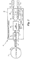
- a crankshaft 1 has secured around its periphery a toothed wheel 2.
- the toothed wheel 2 has positions for thirty-six evenly spaced teeth 4 with gaps 6 of equal width to the teeth therebetween. Each tooth and gap therefore represents 5° of angle.
- One of the thirty-six teeth is missing, leaving a gap 8 three times longer than the other gaps 6.
- the gap 8 is therefore equivalent to 15° of crankshaft rotation.
- a variable reluctance sensor, or VRS (not shown) produces a raw sinusoidal VRS output signal 10, which is inverted and digitized into a buffered VRS signal, or BVRS 12.
- Each of the thirty-five pulses in the BVRS signal therefore has a period equivalent to 10° of crankshaft rotation.
- the toothed wheel rotates anticlockwise, as indicated by the arrow 14 and is illustrated for convenience with top dead centre (TDC) at the top of the drawing.
- TDC top dead centre
- the start of the 15° gap 8 for the missing tooth is set to occur at 100° before TDC.
- PIP Profile Ignition Pickup
- the prior art system used one or the other of these PIP pulses to schedule both the start of charging and beginning of the spark discharge.
- the preferred embodiment of the invention described hereinafter uses reference edges 118,120 of one or the other of the BVRS pulses at the same angles to schedule the start of charging of the coil.
- FIG. 2 shows a preferred embodiment of an ignition system 21, the so-called "36-1 toothed wheel" 2 rotates past a VRS sensor 22 to produce the raw VRS signal 10, which is passed to a buffering input 24 of an engine management module 26.
- the module comprises a microprocessor unit 28 based on an 8065 chip manufactured by Intel Corporation.
- the microprocessor unit uses the input BVRS signal 12 to calculate the correct time for the start of charging and the beginning of discharging, of one or the other of a pair of coils 30,32 and supplies a digital output signal 34,36 to one or the other of a pair of coil drivers 38,40, which in turn produce drive signals 42,44 for the coils 30,32.
- Each coil driver also produces an analogue output 46,48 passed to a comparator 50, which supplies a digital output 52 to the microprocessor 28 which goes high when either one or the other of the coils has been charged half way.
- the dwell time T D to charge the coil may vary depending on a number of factors, particularly the battery voltage and the coil resistance, which is a function of coil temperature. Therefore, the signal microprocessor 28 uses the digital signal 52 to calculate an expected or predetermined dwell time for charging the coil.
- the microprocessor will aim to discharge the coil at a particular desired spark angle 54, here 20°.
- the expected dwell time T D terminates in the discharge of the coil and the spark event.
- the frequency with which the BVRS pulses reach the microprocessor 28 is a measure of the engine speed at a given instant, and from this, the microprocessor 28 can determine an expected time interval I E starting from the detected edge 118 of the BVRS signal until the occurrence of the desired spark angle 54. Since the dwell time T D is predetermined, a time interval I C from the edge 118 to the start of charging is also known, and the microprocessor 28 therefore begins to charge the coil at this time. In this example, this time interval begins at 58° before TDC.
- the microprocessor selects a particular pulse in the series of BVRS pulses occurring after the start of charging and before the end of the expected interval I E .
- the microprocessor selects the pulse 56 immediately preceding the pulse during which the spark event will occur; instead the microprocessor selects the leading edge 58 of the penultimate pulse 60 prior to that pulse 56 as the basis for calculating a time interval, referred to hereinafter as a discharge interval I D , ending in the discharge of the coil.
- the penultimate pulse is therefore the 'first particular pulse' mentioned above occurring after charging starts and before discharging beings from which the 'first interval' is calculated.
- the discharge interval I D is calculated based on the measured engine speed as determined by the frequency of the BVRS pulses immediately preceding the penultimate pulse 56, and from the angle, here 20°, calculated between the desired spark angle 54 and the penultimate pulse leading edge 58.
- the discharge of the coil is then scheduled at the end of the discharge interval I D .
- the microprocessor 28 selects one or the other of the BVRS pulse reference edges 118,120 from which to base its calculation of the expected interval I E and the time interval I C to start of charging.
- One of the pulses associated with the BVRS reference edges 118,120 is therefore the 'second particular pulse' mentioned above occurring before charging starts from which the 'second interval' is calculated.
- pulses progressively further from the pulse 56 at the spark angle are selected by the microprocessor 28 for the calculation of the discharge interval I D .
- the pulse from which the interval I D is calculated may be up to 60° prior to the desired spark angle.
- the dwell time T D may, for larger time intervals I C vary from its optimum value. This however, is not a particular problem as long as the nominal coil charge is sufficiently beyond a minimum level. It would, however, be possible to ensure that the dwell time was more optimal by selecting one of the BVRS pulses prior to the start of coil charging, for example a penultimate prior pulse, in a similar manner to that described above for scheduling the coil discharge.
- An ignition system as described above may be used to improve the control of the spark angle and, optionally, of the dwell time.
- the ignition system improves scheduling of the spark event, and optionally the amount of coil charging when the engine speed is varying significantly.
Landscapes
- Engineering & Computer Science (AREA)
- Chemical & Material Sciences (AREA)
- Combustion & Propulsion (AREA)
- Mechanical Engineering (AREA)
- General Engineering & Computer Science (AREA)
- Physics & Mathematics (AREA)
- Electromagnetism (AREA)
- Ignition Installations For Internal Combustion Engines (AREA)
Applications Claiming Priority (2)
| Application Number | Priority Date | Filing Date | Title |
|---|---|---|---|
| GB9711137A GB2325703A (en) | 1997-05-30 | 1997-05-30 | Internal combustion engine spark scheduling |
| GB9711137 | 1997-05-30 |
Publications (3)
| Publication Number | Publication Date |
|---|---|
| EP0881383A2 true EP0881383A2 (fr) | 1998-12-02 |
| EP0881383A3 EP0881383A3 (fr) | 2000-07-26 |
| EP0881383B1 EP0881383B1 (fr) | 2003-03-26 |
Family
ID=10813266
Family Applications (1)
| Application Number | Title | Priority Date | Filing Date |
|---|---|---|---|
| EP98304261A Expired - Lifetime EP0881383B1 (fr) | 1997-05-30 | 1998-05-29 | Planification d'étincelle pour moteur à combustion interne |
Country Status (4)
| Country | Link |
|---|---|
| US (1) | US6012427A (fr) |
| EP (1) | EP0881383B1 (fr) |
| DE (1) | DE69812473T2 (fr) |
| GB (1) | GB2325703A (fr) |
Cited By (5)
| Publication number | Priority date | Publication date | Assignee | Title |
|---|---|---|---|---|
| EP1705370A3 (fr) * | 2005-03-18 | 2006-11-22 | R.E. Phelon Company, Inc. | Système de commande d'allumage inductif |
| FR2922966A1 (fr) * | 2007-10-30 | 2009-05-01 | Siemens Vdo Automotive Sas | Procede de commande de l'allumage d'un moteur a essence |
| WO2014010164A1 (fr) * | 2012-07-09 | 2014-01-16 | Yamaha Hatsudoki Kabushiki Kaisha | Système de synchronisation pour un moteur à combustion interne pourvu d'une roue dentée présentant plus de deux positions de référence |
| WO2015185791A1 (fr) * | 2014-06-06 | 2015-12-10 | Wärtsilä Finland Oy | Procédé de détermination d'angle à l'allumage dans un moteur à combustion interne à piston |
| EP2990640A4 (fr) * | 2013-04-26 | 2017-01-18 | Yamaha Hatsudoki Kabushiki Kaisha | Système de moteur et véhicule équipé de celui-ci |
Families Citing this family (7)
| Publication number | Priority date | Publication date | Assignee | Title |
|---|---|---|---|---|
| US6313625B1 (en) * | 1999-01-19 | 2001-11-06 | Ford Global Technologies, Inc. | Magnetic rotary position sensing |
| DE10015573A1 (de) * | 2000-03-29 | 2001-10-04 | Mtu Friedrichshafen Gmbh | Verfahren zur Detektion von Zündaussetzern anhand der Kurbelwellendrehzahl |
| JP3748522B2 (ja) * | 2001-06-18 | 2006-02-22 | 三菱電機株式会社 | 内燃機関の制御システム |
| DE102004014369A1 (de) * | 2004-03-24 | 2005-10-13 | Robert Bosch Gmbh | Verfahren zur Steuerung einer Brennkraftmaschine |
| DE102009047219A1 (de) * | 2009-11-27 | 2011-06-01 | Robert Bosch Gmbh | Verfahren und Vorrichtung zum Betreiben eines Verbrennungsmotors |
| DE102011017773A1 (de) | 2011-04-29 | 2012-10-31 | Bayerische Motoren Werke Aktiengesellschaft | Lagerung einer Welle mit radialer Fluidzufuhr in die Welle |
| DE102018219004B4 (de) * | 2017-11-29 | 2021-11-04 | Prüfrex engineering e motion gmbh & co. kg | Zündvorrichtung |
Family Cites Families (8)
| Publication number | Priority date | Publication date | Assignee | Title |
|---|---|---|---|---|
| CH557471A (de) * | 1972-11-10 | 1974-12-31 | Bbc Brown Boveri & Cie | Anordnung fuer die bestimmung der zeitpunkte fuer das speichern und abgeben von energie bei zuendanlagen fuer brennkraftmaschinen. |
| JPS5949427B2 (ja) * | 1976-12-17 | 1984-12-03 | 株式会社日本自動車部品総合研究所 | 内燃機関用電子式点火時期制御装置 |
| JPS55109760A (en) * | 1979-02-19 | 1980-08-23 | Hitachi Ltd | Electronic ignition control |
| US4426974A (en) * | 1982-03-01 | 1984-01-24 | Allied Corporation | Digital timing circuit for a rotating machine |
| US4487183A (en) * | 1983-04-27 | 1984-12-11 | Motorola, Inc. | Speed dependent ignition controller and method |
| US5184590A (en) * | 1991-02-12 | 1993-02-09 | Mitsubishi Denki Kabushiki Kaisha | Engine timing control apparatus |
| US5099811A (en) * | 1991-05-10 | 1992-03-31 | Chrysler Corporation | Method for firing spark plugs |
| US5467752A (en) * | 1992-09-04 | 1995-11-21 | Hitachi, Ltd. | Method and apparatus for controlling the fuel injection/ignition timing of internal combustion engines, and a crank angle sensor using same |
-
1997
- 1997-05-30 GB GB9711137A patent/GB2325703A/en not_active Withdrawn
-
1998
- 1998-05-29 EP EP98304261A patent/EP0881383B1/fr not_active Expired - Lifetime
- 1998-05-29 DE DE69812473T patent/DE69812473T2/de not_active Expired - Fee Related
- 1998-05-29 US US09/087,590 patent/US6012427A/en not_active Expired - Fee Related
Cited By (9)
| Publication number | Priority date | Publication date | Assignee | Title |
|---|---|---|---|---|
| EP1705370A3 (fr) * | 2005-03-18 | 2006-11-22 | R.E. Phelon Company, Inc. | Système de commande d'allumage inductif |
| US7475672B2 (en) | 2005-03-18 | 2009-01-13 | R.E. Phelon Company, Inc. | Inductive ignition control system |
| FR2922966A1 (fr) * | 2007-10-30 | 2009-05-01 | Siemens Vdo Automotive Sas | Procede de commande de l'allumage d'un moteur a essence |
| WO2009056269A1 (fr) * | 2007-10-30 | 2009-05-07 | Continental Automotive France | Procede de commande de l'allumage d'un moteur a essence |
| CN101842581B (zh) * | 2007-10-30 | 2012-03-14 | 法国欧陆汽车公司 | 汽油发动机点火的控制方法 |
| US8510023B2 (en) | 2007-10-30 | 2013-08-13 | Continental Automotive France | Method of controlling the ignition of a gasoline engine |
| WO2014010164A1 (fr) * | 2012-07-09 | 2014-01-16 | Yamaha Hatsudoki Kabushiki Kaisha | Système de synchronisation pour un moteur à combustion interne pourvu d'une roue dentée présentant plus de deux positions de référence |
| EP2990640A4 (fr) * | 2013-04-26 | 2017-01-18 | Yamaha Hatsudoki Kabushiki Kaisha | Système de moteur et véhicule équipé de celui-ci |
| WO2015185791A1 (fr) * | 2014-06-06 | 2015-12-10 | Wärtsilä Finland Oy | Procédé de détermination d'angle à l'allumage dans un moteur à combustion interne à piston |
Also Published As
| Publication number | Publication date |
|---|---|
| DE69812473D1 (de) | 2003-04-30 |
| EP0881383B1 (fr) | 2003-03-26 |
| GB9711137D0 (en) | 1997-07-23 |
| GB2325703A (en) | 1998-12-02 |
| US6012427A (en) | 2000-01-11 |
| EP0881383A3 (fr) | 2000-07-26 |
| DE69812473T2 (de) | 2003-10-30 |
Similar Documents
| Publication | Publication Date | Title |
|---|---|---|
| EP0357197B1 (fr) | Procédé de prédiction de l'instant d'allumage | |
| EP0881383B1 (fr) | Planification d'étincelle pour moteur à combustion interne | |
| US4413508A (en) | Adjusting system for crank angle sensor | |
| US4399802A (en) | Ignition energy control method and system | |
| GB2043171A (en) | Internal combustion engine ignition timing control | |
| US5184590A (en) | Engine timing control apparatus | |
| US4378778A (en) | Ignition system for internal combustion engines | |
| US4699106A (en) | Knock control system for internal combustion engines | |
| GB2209191A (en) | Engine ingition timing control system | |
| US5726892A (en) | Engine speed prediction method for engine control | |
| US4584978A (en) | Method and apparatus for controlling spark timing in internal combustion engines | |
| US5186144A (en) | Ignition control system with cylinder identification evaluation | |
| US4747382A (en) | Ignition timing control system for internal combustion engines | |
| US5263450A (en) | Control apparatus for a multi-cylinder internal combustion engine | |
| US4711213A (en) | Knock control system for internal combustion engines | |
| USRE34183E (en) | Ignition control system for internal combustion engines with simplified crankshaft sensing and improved coil charging | |
| US6032649A (en) | Engine control system | |
| US4596218A (en) | LPP combustion control for IC engine with abnormal combustion | |
| US4817574A (en) | Feed system for injection nozzles | |
| US4452206A (en) | Ignition timing control system for internal combustion engines | |
| JP4638603B2 (ja) | 点火制御装置及び方法 | |
| US4936275A (en) | Ignition control device for internal combustion engine with prediction of timing ratio | |
| US7475672B2 (en) | Inductive ignition control system | |
| JPS592796B2 (ja) | 内燃機関用点火装置 | |
| GB2337136A (en) | Regulating an engine using a transmitter wheel with a reference mark |
Legal Events
| Date | Code | Title | Description |
|---|---|---|---|
| PUAI | Public reference made under article 153(3) epc to a published international application that has entered the european phase |
Free format text: ORIGINAL CODE: 0009012 |
|
| AK | Designated contracting states |
Kind code of ref document: A2 Designated state(s): DE FR GB |
|
| AX | Request for extension of the european patent |
Free format text: AL;LT;LV;MK;RO;SI |
|
| 17P | Request for examination filed |
Effective date: 19981127 |
|
| PUAL | Search report despatched |
Free format text: ORIGINAL CODE: 0009013 |
|
| AK | Designated contracting states |
Kind code of ref document: A3 Designated state(s): AT BE CH CY DE DK ES FI FR GB GR IE IT LI LU MC NL PT SE |
|
| AX | Request for extension of the european patent |
Free format text: AL;LT;LV;MK;RO;SI |
|
| RIC1 | Information provided on ipc code assigned before grant |
Free format text: 7F 02P 7/077 A, 7F 02P 7/067 B, 7F 02P 3/045 B |
|
| AKX | Designation fees paid |
Free format text: DE FR GB |
|
| 17Q | First examination report despatched |
Effective date: 20011002 |
|
| GRAH | Despatch of communication of intention to grant a patent |
Free format text: ORIGINAL CODE: EPIDOS IGRA |
|
| GRAH | Despatch of communication of intention to grant a patent |
Free format text: ORIGINAL CODE: EPIDOS IGRA |
|
| GRAA | (expected) grant |
Free format text: ORIGINAL CODE: 0009210 |
|
| AK | Designated contracting states |
Designated state(s): DE FR GB |
|
| REG | Reference to a national code |
Ref country code: GB Ref legal event code: FG4D |
|
| REF | Corresponds to: |
Ref document number: 69812473 Country of ref document: DE Date of ref document: 20030430 Kind code of ref document: P |
|
| ET | Fr: translation filed | ||
| PLBE | No opposition filed within time limit |
Free format text: ORIGINAL CODE: 0009261 |
|
| STAA | Information on the status of an ep patent application or granted ep patent |
Free format text: STATUS: NO OPPOSITION FILED WITHIN TIME LIMIT |
|
| 26N | No opposition filed |
Effective date: 20031230 |
|
| PGFP | Annual fee paid to national office [announced via postgrant information from national office to epo] |
Ref country code: DE Payment date: 20040525 Year of fee payment: 7 |
|
| PGFP | Annual fee paid to national office [announced via postgrant information from national office to epo] |
Ref country code: FR Payment date: 20040526 Year of fee payment: 7 |
|
| PGFP | Annual fee paid to national office [announced via postgrant information from national office to epo] |
Ref country code: GB Payment date: 20050517 Year of fee payment: 8 |
|
| PG25 | Lapsed in a contracting state [announced via postgrant information from national office to epo] |
Ref country code: DE Free format text: LAPSE BECAUSE OF NON-PAYMENT OF DUE FEES Effective date: 20051201 |
|
| PG25 | Lapsed in a contracting state [announced via postgrant information from national office to epo] |
Ref country code: FR Free format text: LAPSE BECAUSE OF NON-PAYMENT OF DUE FEES Effective date: 20060131 |
|
| REG | Reference to a national code |
Ref country code: FR Ref legal event code: TP Ref country code: FR Ref legal event code: ST Effective date: 20060131 |
|
| PG25 | Lapsed in a contracting state [announced via postgrant information from national office to epo] |
Ref country code: GB Free format text: LAPSE BECAUSE OF NON-PAYMENT OF DUE FEES Effective date: 20060529 |
|
| GBPC | Gb: european patent ceased through non-payment of renewal fee |
Effective date: 20060529 |