EP0881447B1 - Echangeur de chaleur et dispositif d'échange de chaleur pour véhicule automobile - Google Patents
Echangeur de chaleur et dispositif d'échange de chaleur pour véhicule automobile Download PDFInfo
- Publication number
- EP0881447B1 EP0881447B1 EP98107377A EP98107377A EP0881447B1 EP 0881447 B1 EP0881447 B1 EP 0881447B1 EP 98107377 A EP98107377 A EP 98107377A EP 98107377 A EP98107377 A EP 98107377A EP 0881447 B1 EP0881447 B1 EP 0881447B1
- Authority
- EP
- European Patent Office
- Prior art keywords
- heat exchanger
- tube
- wall sections
- flow
- tube ends
- Prior art date
- Legal status (The legal status is an assumption and is not a legal conclusion. Google has not performed a legal analysis and makes no representation as to the accuracy of the status listed.)
- Expired - Lifetime
Links
- 238000010276 construction Methods 0.000 claims description 8
- 238000002955 isolation Methods 0.000 claims description 4
- 230000007704 transition Effects 0.000 claims description 3
- XLYOFNOQVPJJNP-UHFFFAOYSA-N water Substances O XLYOFNOQVPJJNP-UHFFFAOYSA-N 0.000 description 40
- 238000009413 insulation Methods 0.000 description 12
- 239000003990 capacitor Substances 0.000 description 9
- 238000005476 soldering Methods 0.000 description 8
- 229910000679 solder Inorganic materials 0.000 description 5
- 238000004519 manufacturing process Methods 0.000 description 3
- 238000000034 method Methods 0.000 description 3
- 238000007789 sealing Methods 0.000 description 3
- 210000000078 claw Anatomy 0.000 description 2
- 229910052751 metal Inorganic materials 0.000 description 2
- 239000002184 metal Substances 0.000 description 2
- 229910000838 Al alloy Inorganic materials 0.000 description 1
- 229910052782 aluminium Inorganic materials 0.000 description 1
- XAGFODPZIPBFFR-UHFFFAOYSA-N aluminium Chemical compound [Al] XAGFODPZIPBFFR-UHFFFAOYSA-N 0.000 description 1
- 239000000498 cooling water Substances 0.000 description 1
- 238000007373 indentation Methods 0.000 description 1
- 238000003780 insertion Methods 0.000 description 1
- 230000037431 insertion Effects 0.000 description 1
- 238000007493 shaping process Methods 0.000 description 1
Images





Classifications
-
- F—MECHANICAL ENGINEERING; LIGHTING; HEATING; WEAPONS; BLASTING
- F28—HEAT EXCHANGE IN GENERAL
- F28F—DETAILS OF HEAT-EXCHANGE AND HEAT-TRANSFER APPARATUS, OF GENERAL APPLICATION
- F28F1/00—Tubular elements; Assemblies of tubular elements
- F28F1/02—Tubular elements of cross-section which is non-circular
- F28F1/025—Tubular elements of cross-section which is non-circular with variable shape, e.g. with modified tube ends, with different geometrical features
-
- F—MECHANICAL ENGINEERING; LIGHTING; HEATING; WEAPONS; BLASTING
- F28—HEAT EXCHANGE IN GENERAL
- F28D—HEAT-EXCHANGE APPARATUS, NOT PROVIDED FOR IN ANOTHER SUBCLASS, IN WHICH THE HEAT-EXCHANGE MEDIA DO NOT COME INTO DIRECT CONTACT
- F28D1/00—Heat-exchange apparatus having stationary conduit assemblies for one heat-exchange medium only, the media being in contact with different sides of the conduit wall, in which the other heat-exchange medium is a large body of fluid, e.g. domestic or motor car radiators
- F28D1/02—Heat-exchange apparatus having stationary conduit assemblies for one heat-exchange medium only, the media being in contact with different sides of the conduit wall, in which the other heat-exchange medium is a large body of fluid, e.g. domestic or motor car radiators with heat-exchange conduits immersed in the body of fluid
- F28D1/04—Heat-exchange apparatus having stationary conduit assemblies for one heat-exchange medium only, the media being in contact with different sides of the conduit wall, in which the other heat-exchange medium is a large body of fluid, e.g. domestic or motor car radiators with heat-exchange conduits immersed in the body of fluid with tubular conduits
- F28D1/0408—Multi-circuit heat exchangers, e.g. integrating different heat exchange sections in the same unit or heat exchangers for more than two fluids
- F28D1/0426—Multi-circuit heat exchangers, e.g. integrating different heat exchange sections in the same unit or heat exchangers for more than two fluids with units having particular arrangement relative to the large body of fluid, e.g. with interleaved units or with adjacent heat exchange units in common air flow or with units extending at an angle to each other or with units arranged around a central element
- F28D1/0435—Combination of units extending one behind the other
-
- F—MECHANICAL ENGINEERING; LIGHTING; HEATING; WEAPONS; BLASTING
- F28—HEAT EXCHANGE IN GENERAL
- F28F—DETAILS OF HEAT-EXCHANGE AND HEAT-TRANSFER APPARATUS, OF GENERAL APPLICATION
- F28F9/00—Casings; Header boxes; Auxiliary supports for elements; Auxiliary members within casings
- F28F9/02—Header boxes; End plates
- F28F9/0219—Arrangements for sealing end plates into casing or header box; Header box sub-elements
- F28F9/0221—Header boxes or end plates formed by stacked elements
-
- F—MECHANICAL ENGINEERING; LIGHTING; HEATING; WEAPONS; BLASTING
- F28—HEAT EXCHANGE IN GENERAL
- F28F—DETAILS OF HEAT-EXCHANGE AND HEAT-TRANSFER APPARATUS, OF GENERAL APPLICATION
- F28F9/00—Casings; Header boxes; Auxiliary supports for elements; Auxiliary members within casings
- F28F9/02—Header boxes; End plates
- F28F9/04—Arrangements for sealing elements into header boxes or end plates
- F28F9/16—Arrangements for sealing elements into header boxes or end plates by permanent joints, e.g. by rolling
-
- F—MECHANICAL ENGINEERING; LIGHTING; HEATING; WEAPONS; BLASTING
- F28—HEAT EXCHANGE IN GENERAL
- F28D—HEAT-EXCHANGE APPARATUS, NOT PROVIDED FOR IN ANOTHER SUBCLASS, IN WHICH THE HEAT-EXCHANGE MEDIA DO NOT COME INTO DIRECT CONTACT
- F28D21/00—Heat-exchange apparatus not covered by any of the groups F28D1/00 - F28D20/00
- F28D2021/0019—Other heat exchangers for particular applications; Heat exchange systems not otherwise provided for
- F28D2021/008—Other heat exchangers for particular applications; Heat exchange systems not otherwise provided for for vehicles
- F28D2021/0082—Charged air coolers
-
- F—MECHANICAL ENGINEERING; LIGHTING; HEATING; WEAPONS; BLASTING
- F28—HEAT EXCHANGE IN GENERAL
- F28D—HEAT-EXCHANGE APPARATUS, NOT PROVIDED FOR IN ANOTHER SUBCLASS, IN WHICH THE HEAT-EXCHANGE MEDIA DO NOT COME INTO DIRECT CONTACT
- F28D21/00—Heat-exchange apparatus not covered by any of the groups F28D1/00 - F28D20/00
- F28D2021/0019—Other heat exchangers for particular applications; Heat exchange systems not otherwise provided for
- F28D2021/008—Other heat exchangers for particular applications; Heat exchange systems not otherwise provided for for vehicles
- F28D2021/0084—Condensers
-
- F—MECHANICAL ENGINEERING; LIGHTING; HEATING; WEAPONS; BLASTING
- F28—HEAT EXCHANGE IN GENERAL
- F28D—HEAT-EXCHANGE APPARATUS, NOT PROVIDED FOR IN ANOTHER SUBCLASS, IN WHICH THE HEAT-EXCHANGE MEDIA DO NOT COME INTO DIRECT CONTACT
- F28D21/00—Heat-exchange apparatus not covered by any of the groups F28D1/00 - F28D20/00
- F28D2021/0019—Other heat exchangers for particular applications; Heat exchange systems not otherwise provided for
- F28D2021/008—Other heat exchangers for particular applications; Heat exchange systems not otherwise provided for for vehicles
- F28D2021/0091—Radiators
- F28D2021/0094—Radiators for recooling the engine coolant
-
- F—MECHANICAL ENGINEERING; LIGHTING; HEATING; WEAPONS; BLASTING
- F28—HEAT EXCHANGE IN GENERAL
- F28F—DETAILS OF HEAT-EXCHANGE AND HEAT-TRANSFER APPARATUS, OF GENERAL APPLICATION
- F28F9/00—Casings; Header boxes; Auxiliary supports for elements; Auxiliary members within casings
- F28F9/001—Casings in the form of plate-like arrangements; Frames enclosing a heat exchange core
- F28F2009/004—Common frame elements for multiple cores
-
- F—MECHANICAL ENGINEERING; LIGHTING; HEATING; WEAPONS; BLASTING
- F28—HEAT EXCHANGE IN GENERAL
- F28F—DETAILS OF HEAT-EXCHANGE AND HEAT-TRANSFER APPARATUS, OF GENERAL APPLICATION
- F28F2275/00—Fastening; Joining
- F28F2275/16—Fastening; Joining with toothed elements, e.g. with serrations
Definitions
- the invention relates to a heat exchanger for a motor vehicle with a rib / tube block, the flat tubes on opposite sides with such expanded pipe ends are provided that transversely, adjacent to each other Wall sections of the pipe ends lie flat against each other and the pipe ends are aligned in a row, wherein on the pipe ends on both sides each have a flow box flush with corresponding longitudinal wall sections the pipe ends is placed, as well as a Heat exchanger arrangement for a motor vehicle with at least two arranged one behind the other in the direction of flow Heat exchangers.
- Such devices are for example out US 4,206,806 known.
- the object of the invention is to provide a heat exchanger and a Heat exchanger arrangement of the type mentioned above create a functionally reliable manufacturing as well as a enable simple and space-saving construction.
- this object is achieved in that the adjacent, transverse wall sections the pipe ends are fixed positively abutting. This makes it possible, already during the pre-assembly of the heat exchanger, i.e. before the soldering of the individual components, an exact alignment and fixation of the pipe ends together to achieve. Tolerances due to a lateral offset individual pipe ends can be avoided. By the form-fitting Plant the wall sections together In addition, an enlarged contact surface, which increased one Safety of the solder joint has the consequence.
- the corners of the expanded pipe ends with radii between 0 and 2 mm provided.
- the expanded tube ends preferably a rectangular shape, which according to the previously described Embodiments additionally with correspondingly deformed wall sections can be provided.
- the preferred radii Ensure that between the adjacent pipe ends too in the area of the outsides only extremely narrow column remain completely through the solder during the soldering process can be filled, so that the dense solder joint with each other and in particular to the lateral wall areas the flow boxes ensured.
- the pipe ends each asymmetrical to the center longitudinal planes of the associated Flat tubes widened. This makes it possible to have special arrangements to realize the components of the heat exchanger, without affecting the safe function of the heat exchanger.
- the scope corresponds the expansion of each pipe end to the extent of the associated Flat tube plus or minus 30%.
- the negative relation between the circumference of each flat tube and the circumference of the associated, expanded pipe end results in particular by a partially double-walled folding the Wall of pipe ends.
- the lateral pipe sections facing the adjacent pipe ends have a height of between 0.3 and 2 times a pitch of the flat pipes, namely 0.3T ⁇ H 1 ⁇ 2T. This preferred dimensioning allows a secure tight connection between the pipe ends and sufficient stability of the entire fins / tube block.
- the flat tubes obliquely relative to the axis of symmetry of the flared pipe ends aligned. Also by this configuration is a special arrangement of the heat exchanger in a motor vehicle possible, in particular an oblique arrangement the heat exchanger within an engine compartment of the motor vehicle - In the normal direction of travel of the motor vehicle based - is advantageous.
- the inventive Problem solved in that the at least two heat exchangers on opposite sides one common each Side part is assigned. Through the common side parts on the one hand, a simple and secure connection of the heat exchanger relative to each other and the other an exact Positioning relative to each other achieved. Furthermore results in a simplified assembly and manufacturing for the Heat exchanger assembly with a reduced number of Components.
- the flow boxes of at least one heat exchanger in their side areas open designed, and the opposite side panels are each with at least one corresponding end portion provided in the respective side areas of the Protrude flow boxes and close them tight.
- the at least two heat exchangers common, over the total depth of the ribs / tube block extending ribs. This will achieves a simplified construction of the heat exchanger arrangement, because the number of components is reduced and the ribs directly the connection of the heat exchangers with each other produce.
- the flow boxes the at least two heat exchanger with connection piece provided, which are parallel to each other and curved in the same direction are aligned. This is a streamlined Arrangement of the connecting piece given, which also saves space acts.
- isolation column arranged between the Pipes and / or the flow boxes isolation column arranged. These insulation gaps are used for thermal insulation the adjacent heat exchanger against each other, wherein the Isolation column preferably each of the tubes over their entire Length up to the respective flow boxes from each other separate. However, this embodiment also detects insulation gaps, the only sections between the adjacent Pipes and / or flow boxes are provided.
- the isolation column have preferred widths between 1 and 10 mm on.
- a heat exchanger assembly 1 for a motor vehicle has a first heat exchanger in the form a water / air cooler, a second heat exchanger in Form of a charge air cooler and a third heat exchanger in the form of a capacitor.
- the three heat exchangers are parallel to each other transversely to the vehicle longitudinal direction in an engine compartment of the motor vehicle arranged so that they are in Direction of flow of the airstream in the normal direction of travel of the motor vehicle are arranged one behind the other.
- the water / air cooler has a in Fig. 1 upper than Flow box serving water tank 2 and a lower Water tank 5, wherein the lower water tank 5 two connecting pieces 9 and 10 for connecting the water / air cooler arranged on the corresponding cooling water circuit are.
- a rib / tube block 4 Between the two water tanks 2 and 5 extends a rib / tube block 4, its structure and its connection with the water boxes 2 and 5 described in more detail below will be.
- Behind the water / air cooler is the intercooler arranged, one serving as a flow box upper air box 3 and a corresponding lower Air box 6 has.
- Between the two air boxes 3 and 6 is analogous to the water / air cooler a not shown Ribs / tube block provided, its construction and its Connection with the air boxes 3 and 6 the corresponding structure of the water / air cooler corresponds.
- Behind the intercooler the capacitor is positioned, which is an upper one Flow box 13 and a lower flow box 14 and one between these flow boxes 13, 14 extending and having unspecified ribs / tube block.
- Flow box 13, 14 is replaced by two to a circular hollow chamber profile composed half-shells, respectively a half-shell a bottom of the respective flow box 13, 14 represents and with indentations for tight connection is provided at pipe ends of the flat tubes.
- the side are the Flow boxes 13, 14 each through a lid insert tightly closed.
- Both the ribs / tube block of the intercooler and the Ribs / tube block of the water / air cooler are of a variety of parallel flat tubes and between composed of these arranged corrugated fins.
- the opposite Pipe ends of the flat tubes are each rectangular expanded, so that the pipe ends of FIG. 1 in each case a row with their in the longitudinal direction of the flow boxes seen transverse wall sections flat and close to each other.
- the longitudinal wall sections the flared pipe ends each run in one Escape to each other.
- the pipe ends, each the outside of the Form ribs / tube block are corresponding, longitudinal Wall areas of the flow boxes flat and flush final.
- the expanded pipe ends form thus directly the bottoms "of the flow boxes, so that the additional Provision of floors in the area of the flow boxes is avoided.
- the described structure of the heat exchanger corresponds to the design of the pipe ends and the placement of the Flow boxes, as in the unpublished DE 195 43 986.4 is described.
- the flow boxes of both the intercooler and the Water / air coolers are on their opposite side areas each designed open.
- This side areas of the flow boxes takes over each a termination section 15, 16, 18, 19 of a side part 11, 12, which integrally over the entire depth of the heat exchanger assembly and thus extends over all three heat exchangers.
- the two side parts 11, 12 limit the ribs / tube blocks the water / air cooler, the intercooler and the capacitor on opposite sides.
- the flow boxes 13, 14 of the Kondenstators have the side parts 11, 12 only a contact portion 17, the on a lower edge of the respective half shell of the flow boxes 13, 14 is supported and thus no lateral sealing function takes over.
- the two side parts 11, 12 are for assembly the heat exchanger assembly from opposite sides attached to the ribs / pipe blocks and simultaneously with their termination sections 15, 16, 18, 19 axially - on the Referred to longitudinal direction of the flow boxes - in the flow boxes used.
- a clamping device such as tension bands or the like, the entire heat exchanger assembly including the side parts 11, 12 in the transverse direction of the Ribs / pipe blocks loaded on pressure and then in a common soldering process soldered tight.
- all components of the heat exchanger assembly 1 made of sheet metal, preferably an aluminum alloy are made. At least the each tight to be joined sections of the individual components of the heat exchanger assembly are soldered accordingly.
- each retaining claws provided in the embodiment of FIG. 7 are provided with the reference numeral 26. These are going to be the axial insertion of the end portions of the side parts 11, 12 bent inwards, wherein they are in corresponding recesses the contact webs of the end portions 15, 16, 18, 19 intervene. Even without the described clamping device Thus, a fixation on the side parts 11, 12 already the flow boxes of the intercooler and the water / air cooler relative to the associated ribs / tube blocks and relative achieved to the side parts 11, 12.
- FIGS. 6 to 8 Another heat exchanger arrangement according to FIGS. 6 to 8 has only two successively arranged heat exchanger of which one as a water / air cooler and the other than capacitor are formed.
- the water / air cooler corresponds in its construction to the previously with reference to FIG. 1 to 5 described in detail water / air cooler of the heat exchanger assembly 1, so that no further explanation necessary is.
- the water / air cooler and the Capacitors are also on opposite sides two associated with common side parts 12a, which correspond in principle accordingly the side panels 11 and 12, but for only two heat exchangers designed, designed.
- Each side part 12a only has one end section 16a in each case for the respective side area of the water box of the water / air cooler on, analogous to the embodiment according to the Fig. 1 to 5 by means of retaining claws 26 in the side areas fixed and then tight with the water boxes are soldered.
- FIG. 9 is a heat exchanger assembly similar to Figs. 6 to 8 shown in fragmentary form, preferably also from a water / air cooler and a capacitor.
- this heat exchanger arrangement a common Having ribs / tube block, in which the flat tubes 21 b of the Condenser on the one hand and the flat tubes 24b of the water / air cooler on the other hand are separated, but the common and over the entire depth of the heat exchanger assembly has continuous corrugated ribs 27.
- the corrugated ribs 27 thus have the same width as those also over the entire heat exchanger assembly extending side panels 12b on.
- the heat exchanger assembly of FIG. 10 is analogous to Heat exchanger assembly of FIG. 9 also with a common Ribs / tube block provided with corrugated fins 28 itself extend over the entire depth of the heat exchanger assembly.
- the heat exchanger arrangement 29 according to FIG. 11 corresponds to FIG their structure basically the embodiment of the Fig. 1 to 5 or Fig. 10.
- a water / air cooler has Flat tubes 30 a not shown ribs / tube block on, on their expanded pipe ends directly water tanks 35 are attached.
- the water boxes 35 are identical and designed symmetrically to each other and each have one Connecting piece 37, according to the illustration according to Fig. 11 parallel to each other in the same direction horrrekken.
- the intercooler has analogous to the water / air cooler designed flat tubes 31 of an associated ribs / tube block on, on whose flared pipe ends on opposite Pages each an air box 34 is placed.
- the air boxes 34 on the opposite sides of the Intercooler are identical and symmetrical to each other, wherein both air boxes each have a terminal manifold each above or below the respective Water box 35 so symmetrical to the water / air cooler is curved, that the inserted connecting piece 36 parallel aligned with the connection piece 37 of the water / air cooler are.
- by virtue of symmetrical, identical construction of the opposite Flow boxes is a simplified manufacture the heat exchanger assembly in particularly high quantities allows.
- the condenser which consists of flow boxes 33 and a flat tubes 32 having ribs / tube block composed is also symmetrical to a median transverse plane (shown in phantom) of the heat exchanger assembly built up.
- the individual heat exchangers according to FIG. 11 are through common side parts and / or over the entire depth the heat exchanger assembly 29 extending corrugated fins to a Entire block analogous to the previously described embodiments firmly connected.
- all components of the heat exchanger and the Heat exchanger assembly for a soldering in a common Soldering process are made of metal.
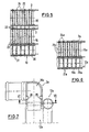
- the heat exchanger arrangements according to FIGS. 8 to 11 have flow boxes (water tank 2a and flow box 13a according to FIG. 8 and water tank 35, air box 34 and flow box 33 according to FIG. 11), which are separated from each other by insulation gaps SP 1 , SP 4 are.
- insulation gaps SP 1 , SP 4 are provided between the water tank 2 a and the flow box 13 a of FIG. 8
- the insulation gap between the water tank 35 and the air box 34 is designed substantially larger.
- the insulation gaps should avoid heat transfer between the different hot or hot flow boxes during operation.
- insulation gaps SP 2 are provided between the tubes 21b, 24b, as well as insulation gaps SP 2 and SP 3 between the tubes 21c, 22c, 24c, which serve for thermal insulation of the adjacent tube blocks (FIGS. 9, 10).
- insulation gaps SP 2 , SP 3 are provided between the tubes 31, 32 and 30, 31.
- All insulation gaps have a width between 1 mm and 10 mm up.
- a heat exchanger as he uses the water / air cooler as well
- the intercooler of the embodiments described above disclosed may have various details, which makes up for a heat exchanger with a principle already described the structure below with reference to FIGS. 12 to 21 listed embodiments result. These details can be either on your own or in optional Combining the respective embodiments of heat exchangers result.
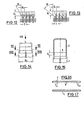
- the flared tube ends of the fin / tube block of a heat exchanger as previously described in principle, provided with a rectangular bulge A, as shown in Fig. 20.
- the width L (FIG. 14) of the longitudinal wall sections of each bulge A is less than the width B 2 (FIG. 14) of the associated flat tubes.
- the longitudinal wall sections extending in the longitudinal direction of the flow boxes have a width B 1 which corresponds to the pitch T of the fin / tube block.
- the height H 1 of the transverse wall sections of the bulges A which corresponds to the height of the contact surface of these wall sections to each other, is between 0.3 and 2 times the pitch T of the rib / tube block, the selection of this area depends on the respective requirements of the heat exchanger is selected.
- each bulge A between the normal flat tube cross-section and the respective end face of the flared tube end has an angle of inclination W - to the surface of the transverse wall portion of the bulge A - on which between 5 ° and 90 °, but preferably between 25 ° and 65 ° lies.
- the transition region either as an inclined plane or only as a direct connection of two radii - from the flat tube on the one hand and from the bulge forth on the other hand - be provided.
- the inclination angle W is then determined by the common tangent of the two radii. As can be seen from FIG.
- the height H 2 of the longitudinal wall sections of each bulge A which serves for the planar soldering of the corresponding wall regions of the respective flow box S, is less than the height H 1 of the transverse wall sections, the ratio of this height H 1 and H 2 is the degree of the bulge A relative to the flat tube F results.
- the degree of bulge is defined inter alia by the ratio of the peripheries of the bulge A on the one hand and the associated flat tube F on the other hand.
- the scope of the bulge A is dimensioned according to preferred embodiments so that it corresponds to the circumference of the associated flat tube F plus or minus 30%.
- the corners of the rectangular bulges A of the flat tubes preferably have an outer radius R a and an inner radius R i , which are between 0 and 2 mm.
- the outer radius R a is so dimensioned that remain only very narrow joints between the adjacent pipe ends and the side walls of the flow boxes, which are completely and tightly filled in the soldering oven by the flowing solder.
- the tube ends of the flat tubes F of the ribs / tube block are expanded asymmetrically, resulting in a central longitudinal plane of each flat tube F staggered bulges A s .
- the adjacent bulges A s are juxtaposed as shown in FIG. 13 to achieve the mutual tight connection.
- the flat tubes form either according to the flat tube F 1 of FIG. 17 a single, continuous flow channel, or are provided according to the embodiment of FIGS. 14 to 16 with two separate flow channels (F S1 , F S2 ), wherein the flat tube F is designed by corresponding longitudinal corrugations N on opposite sides.
- the two flow channels can also be created by a correspondingly extruded aluminum profile.
- more than two flow channels are provided in a flat tube.
- FIGS 21 show various exemplary embodiments which further improve the bottomless "heat exchangers, in which flow boxes are placed directly on the widened tube ends of the rib / tube block .
- a form-fitting fixation of the widened tube ends to one another transversely to the longitudinal direction of the flow boxes, not shown, is achieved by a corresponding shaping of the transverse wall sections of the widened tube ends A 1 , A 2 , A 3 and A 6 19 arcuately curved in the embodiment according to Fig. 19.
- the wall sections of the embodiment according to Fig. 20 have arcuate curvatures which run between rectilinear webs of the wall sections As shown in FIG. 21, the wall sections are also wavy, with the waveform extending to the transverse wall sections and not transitioning to linear webs, as in the embodiment of FIG. 19.
Landscapes
- Engineering & Computer Science (AREA)
- Physics & Mathematics (AREA)
- Thermal Sciences (AREA)
- Mechanical Engineering (AREA)
- General Engineering & Computer Science (AREA)
- Geometry (AREA)
- Heat-Exchange Devices With Radiators And Conduit Assemblies (AREA)
- Sorption Type Refrigeration Machines (AREA)
- Cooling, Air Intake And Gas Exhaust, And Fuel Tank Arrangements In Propulsion Units (AREA)
Claims (19)
- Échangeur de chaleur pour un véhicule automobile comprenant un bloc tubulaire à ailettes, dont les tubes plats sont prévus sur des côtés opposés avec des extrémités de tube élargies de telle sorte que des parties de paroi, agencées transversalement et voisines les unes les autres, des extrémités de tube sont disposées les unes contre les autres à plat et les extrémités de tube sont alignées entre elles dans une rangée, un caisson d'écoulement étant posé sur chacune des deux extrémités de tube sur les deux côtés en se terminant en affleurement avec des parties de paroi correspondantes des extrémités de tube, agencées dans la longueur, caractérisé en ce que les parties de paroi, voisines les unes les autres et agencées transversalement, des extrémités de tube (A1, A2, A3, A6) sont fixées disposées les unes contre les autres par complémentarité de forme.
- Échangeur de chaleur selon la revendication 1, caractérisé en ce que les parties de paroi, tournées vers les caissons d'écoulement (S1, S2) et agencées dans la longueur, des extrémités de tube (A4, A5) s'appuient par complémentarité de forme sur des zones de paroi correspondantes des caissons d'écoulement (S1, S2 ) .
- Échangeur de chaleur selon la revendication 1 ou 2, caractérisé en ce que les parties de paroi, tournées les unes vers les autres et agencées transversalement, des extrémités de tube (A2) voisines sont pourvues de courbures correspondantes entre elles, de forme ondulée ou de forme arquée.
- Échangeur de chaleur selon la revendication 2 ou 3, caractérisé en ce que les parties de paroi agencées dans la longueur des extrémités de tube (A4, A5) sont pourvues chacune d'au moins une courbure ou d'un angle dépassant de l'alignement des parties de paroi et en ce que les zones de paroi attribuées des caissons d'écoulement (S1, S2) sont agencées avec une courbure ou une dentelure opposée et appropriée.
- Échangeur de chaleur selon l'une quelconque des revendications précédentes, caractérisé en ce que les angles des extrémités de tube (A) élargies sont pourvus de rayon (Ri, Ra) compris entre 0 et 2 mm.
- Échangeur de chaleur selon l'une quelconque des revendications précédentes, caractérisé en ce que les extrémités de tube (As) sont élargies respectivement' de façon asymétrique par rapport à un plan médian du tube plat (7) attribué.
- Échangeur de chaleur selon l'une quelconque des revendications précédentes, caractérisé en ce que le pourtour de l'élargissement (A) de chaque extrémité du tube correspond au pourtour du tube plat (F, F1) attribué plus ou moins 30 %.
- Échangeur de chaleur selon l'une quelconque des revendications précédentes, caractérisé en ce qu'une zone de transition entre l'élargissement de l'extrémité de tube et une enveloppe de tube plat est inclinée dans un angle (W) compris entre 5° et 90°, de préférence entre 25° et 65°, par rapport à la partie de paroi côté transversal de l'élargissement.
- Échangeur de chaleur selon l'une quelconque des revendications précédentes, caractérisé en ce que l'extension (L) des parties de paroi agencées transversalement est plus faible que la largeur (B2) des tubes plats.
- Échangeur de chaleur selon l'une quelconque des revendications précédentes, caractérisé en ce que les parties de paroi agencées transversalement et tournées vers les extrémités de tube voisines présentent une hauteur (H1) comprise entre 0,3 et 2 fois un espacement de graduation (T) des tubes plats, c'est-à-dire 0,3 T ≤ H1 ≤ 2T.
- Échangeur de chaleur selon l'une quelconque des revendications précédentes, caractérisé en ce que la hauteur (H2) de la surface de brasage des parties de paroi agencées longitudinalement et tournées vers le bac collecteur (S) est plus faible que la hauteur (H1) des parties de paroi,agencées transversalement.
- Échangeur de chaleur selon l'une quelconque des revendications précédentes, caractérisé en ce que les tubes plats (F2) sont orientés et agencés en biais par rapport à des axes de symétrie des élargissements (A) des extrémités de tube.
- Dispositif d'échange de chaleur pour un véhicule automobile avec au moins deux échangeurs de chaleur disposés l'un derrière l'autre dans le sens d'écoulement selon la revendication 1, caractérisé en ce qu'une partie latérale (11, 12, 12a) commune est attribuée respectivement à au moins deux échangeurs de chaleur sur des côtés opposés.
- Dispositif d'échange de chaleur selon la revendication 13, caractérisé en ce que les caissons d'écoulement (2, 3, 5, 6, 2a) d'au moins un échangeur de chaleur sont conçus de façon ouverte dans leurs zones latérales et en ce que les parties latérales (11, 12, 12a) opposées sont pourvues chacune d'au moins une partie de fermeture correspondante, lesquelles dépassent dans les zones latérales respectives des caissons d'écoulement (2, 3, 5, 6, 2a) et ferment ces caissons de façon étanche.
- Dispositif d'échange de chaleur selon la revendication 14, caractérisé en ce que les contours extérieurs des parties de fermeture sont adaptés aux contours intérieurs correspondants des zones latérales des caissons d'écoulement (2, 3, 5, 6, 2a).
- Dispositif d'échange de chaleur selon l'une quelconque des revendications 13 à 15, caractérisé en ce que les au moins deux échangeurs de chaleur présentent des ailettes communes et s'étendant sur toute la profondeur du bloc tubulaire à ailettes.
- Dispositif d'échange de chaleur selon l'une quelconque des revendications précédentes, caractérisé en ce que les tubes plats (F) d'au moins un bloc tubulaire à ailettes forment respectivement au moins deux canaux d'écoulement (Fs1, Fs2) parallèles entre eux.
- Dispositif d'échange de chaleur selon l'une quelconque des revendications précédentes, caractérisé en ce que les caissons d'écoulement (34, 35) et au moins deux échangeurs de chaleur sont pourvus de tubulures de raccordement (36, 37) qui sont incurvées parallèlement entre elles et dans le même sens.
- Dispositif d'échange de chaleur selon l'une quelconque des revendications 13 à 18, caractérisé en ce que des fentes d'isolation (SP1, SP2, SP3, SP4) sont disposées entre les tubes (21b ; 24b ; 21c, 22c, 24c ; 30, 31, 32) et/ou les caissons d'écoulement (2a, 13a ; 33, 34, 35).
Priority Applications (1)
| Application Number | Priority Date | Filing Date | Title |
|---|---|---|---|
| EP04008664A EP1435503B1 (fr) | 1997-05-27 | 1998-04-23 | Echangeur de chaleur et ensemble échangeur de chaleur pour véhicules automobiles |
Applications Claiming Priority (2)
| Application Number | Priority Date | Filing Date | Title |
|---|---|---|---|
| DE19722097A DE19722097A1 (de) | 1997-05-27 | 1997-05-27 | Wärmeübertrager sowie Wärmeübertrageranordnung für ein Kraftfahrzeug |
| DE19722097 | 1997-05-27 |
Related Child Applications (1)
| Application Number | Title | Priority Date | Filing Date |
|---|---|---|---|
| EP04008664A Division EP1435503B1 (fr) | 1997-05-27 | 1998-04-23 | Echangeur de chaleur et ensemble échangeur de chaleur pour véhicules automobiles |
Publications (3)
| Publication Number | Publication Date |
|---|---|
| EP0881447A2 EP0881447A2 (fr) | 1998-12-02 |
| EP0881447A3 EP0881447A3 (fr) | 1999-06-23 |
| EP0881447B1 true EP0881447B1 (fr) | 2004-08-18 |
Family
ID=7830602
Family Applications (2)
| Application Number | Title | Priority Date | Filing Date |
|---|---|---|---|
| EP98107377A Expired - Lifetime EP0881447B1 (fr) | 1997-05-27 | 1998-04-23 | Echangeur de chaleur et dispositif d'échange de chaleur pour véhicule automobile |
| EP04008664A Expired - Lifetime EP1435503B1 (fr) | 1997-05-27 | 1998-04-23 | Echangeur de chaleur et ensemble échangeur de chaleur pour véhicules automobiles |
Family Applications After (1)
| Application Number | Title | Priority Date | Filing Date |
|---|---|---|---|
| EP04008664A Expired - Lifetime EP1435503B1 (fr) | 1997-05-27 | 1998-04-23 | Echangeur de chaleur et ensemble échangeur de chaleur pour véhicules automobiles |
Country Status (5)
| Country | Link |
|---|---|
| US (1) | US6012512A (fr) |
| EP (2) | EP0881447B1 (fr) |
| JP (1) | JPH1114271A (fr) |
| DE (3) | DE19722097A1 (fr) |
| ES (1) | ES2226025T3 (fr) |
Cited By (1)
| Publication number | Priority date | Publication date | Assignee | Title |
|---|---|---|---|---|
| EP1748271A1 (fr) | 2005-07-30 | 2007-01-31 | Dr.Ing. h.c.F. Porsche Aktiengesellschaft | Tubes et ailettes pour bloc d'échange de chaleur |
Families Citing this family (38)
| Publication number | Priority date | Publication date | Assignee | Title |
|---|---|---|---|---|
| US6390192B2 (en) * | 1998-03-31 | 2002-05-21 | Well, Well, Well, Inc. | Integral well filter and screen and method for making and using same |
| DE19846267A1 (de) * | 1998-10-08 | 2000-04-13 | Behr Gmbh & Co | Sammelrohreinheit für einen Wärmeübertrager |
| DE19858325B4 (de) * | 1998-12-17 | 2009-01-15 | Behr Gmbh & Co. Kg | Wärmeübertrageranordnung für ein Kraftfahrzeug |
| JP4379967B2 (ja) * | 1999-03-30 | 2009-12-09 | 株式会社デンソー | 複式熱交換器 |
| JP2001012893A (ja) * | 1999-04-27 | 2001-01-19 | Denso Corp | 複式熱交換器 |
| DE19921273A1 (de) * | 1999-05-07 | 2000-11-09 | Behr Industrietech Gmbh & Co | Wärmeübertrager, insbesondere für Schienenfahrzeuge |
| US6530424B2 (en) * | 1999-06-02 | 2003-03-11 | Long Manufacturing Ltd. | Clip on manifold heat exchanger |
| CA2273456C (fr) * | 1999-06-02 | 2008-09-23 | Long Manufacturing Ltd. | Echangeur de chaleur de tubulures d'admission a applique |
| US6332495B1 (en) * | 1999-06-02 | 2001-12-25 | Long Manufacturing Ltd. | Clip on manifold heat exchanger |
| FR2800451B1 (fr) * | 1999-10-27 | 2002-01-18 | Valeo Thermique Moteur Sa | Echangeur de chaleur a encombrement reduit et equipement d'un vehicule automobile comportant un tel echangeur de chaleur |
| DE19957307A1 (de) * | 1999-11-29 | 2001-05-31 | Behr Gmbh & Co | Zweikreis-Wärmeübertrager |
| DE19961199B4 (de) * | 1999-12-18 | 2007-10-04 | Modine Manufacturing Co., Racine | Wärmeübertrageranordnung |
| FR2805121B1 (fr) * | 2000-02-11 | 2002-04-26 | Leroy Somer | Convertisseur modulaire |
| DE10033070A1 (de) * | 2000-03-31 | 2002-01-17 | Modine Mfg Co | Kühler für Kraftfahrzeuge sowie Herstellungsverfahren |
| DE10016113A1 (de) * | 2000-03-31 | 2001-10-04 | Modine Mfg Co | Kühler für Kraftfahrzeuge und Herstellungsverfahren |
| DE10138247A1 (de) * | 2001-08-03 | 2003-02-13 | Behr Gmbh & Co | Wärmetauscheranordnung |
| DE10147192A1 (de) | 2001-09-25 | 2003-04-17 | Modine Mfg Co | Wärmeaustauscher mit einem Rippen-Flachrohr-Block und Herstellungsverfahren |
| DE10219867A1 (de) * | 2002-05-03 | 2003-11-20 | Behr Gmbh & Co | Wärmetauscher, insbesondere Ladeluftkühler |
| DE10227929A1 (de) * | 2002-06-21 | 2004-01-08 | Behr Gmbh & Co. | Wärmeübertrageranordnung |
| DE10229083A1 (de) | 2002-06-28 | 2004-01-15 | Modine Manufacturing Co., Racine | Wärmetauscher mit einem Diffusor |
| US7159650B2 (en) * | 2002-06-28 | 2007-01-09 | Modine Manufacturing Company | Heat exchanger |
| US6751536B1 (en) * | 2002-12-04 | 2004-06-15 | The Boeing Company | Diagnostic system and method for enabling multistage decision optimization for aircraft preflight dispatch |
| DE10321458A1 (de) * | 2003-05-13 | 2004-12-02 | Behr Gmbh & Co. Kg | Wärmetauschereinheit für Kraftfahrzeuge |
| DE10344219A1 (de) | 2003-09-22 | 2005-04-14 | Behr Gmbh & Co. Kg | Wärmeübertragermodul für ein Kraftfahrzeug |
| CA2443496C (fr) * | 2003-09-30 | 2011-10-11 | Dana Canada Corporation | Echangeurs de chaleur a faisceau comprenant des tubes a extremite de section elargie |
| DE10347180A1 (de) * | 2003-10-10 | 2005-05-12 | Modine Mfg Co | Wärmeaustauscher, insbesondere für Kraftfahrzeuge |
| DE10348699A1 (de) * | 2003-10-16 | 2005-05-12 | Behr Gmbh & Co Kg | Kühlmittelkühler eines Kraftfahrzeuges |
| DE10348701A1 (de) | 2003-10-16 | 2005-05-12 | Behr Gmbh & Co Kg | Anordnung zur Befestigung eines Wärmeübertragers an einem anderen |
| US7059050B2 (en) * | 2004-01-08 | 2006-06-13 | Delphi Technologies, Inc. | One piece integral reinforcement with angled end caps to facilitate assembly to core |
| DE102004003047A1 (de) * | 2004-01-20 | 2005-08-11 | Behr Gmbh & Co. Kg | Wärmeübertrager, insbesondere Kühlmittel- oder Ladeluftkühler für Kraftfahrzeuge |
| DE102004050160A1 (de) * | 2004-10-14 | 2006-04-27 | Behr Gmbh & Co. Kg | Verfahren zum Herstellen einer Wellrippe und Wärmeübertragerblock mit nach dem Verfahren hergestellten Wellrippen |
| DE102004053892A1 (de) * | 2004-11-09 | 2006-05-11 | Modine Manufacturing Co., Racine | Wärmeübertrager |
| US7195060B2 (en) * | 2005-04-01 | 2007-03-27 | Dana Canada Corporation | Stacked-tube heat exchanger |
| JP4640288B2 (ja) * | 2005-12-09 | 2011-03-02 | 株式会社デンソー | インタークーラ |
| DE102007006235A1 (de) | 2007-02-08 | 2008-08-14 | Behr Gmbh & Co. Kg | Wärmeübertrager in Ganzaluminiumbauweise, insbesondere für Kraftfahrzeuge |
| DE102007052888A1 (de) * | 2007-11-02 | 2009-05-07 | Behr Gmbh & Co. Kg | Wärmeübertrager, insbesondere für ein Fahrzeug |
| RU2536037C2 (ru) * | 2012-08-08 | 2014-12-20 | Владимир Германович Мазеин | Заготовка радиаторной секции трубчато-пластинчатого радиатора, радиаторный блок, изготовленный из этой заготовки, и радиатор, изготовленный из этого блока |
| KR101405234B1 (ko) * | 2013-06-05 | 2014-06-10 | 현대자동차 주식회사 | 차량용 라디에이터 |
Family Cites Families (28)
| Publication number | Priority date | Publication date | Assignee | Title |
|---|---|---|---|---|
| DE527341C (de) * | 1931-06-17 | Friedrich Emil Krauss | Kuehler aus Schwarzblech fuer Kraftfahrzeuge | |
| DE7229162U (de) * | 1973-10-04 | Kuehlerfabrik Laengerer & Reich | Wärmeaustauscher, insbesondere Kühler für eine Brennkraftmaschine | |
| US713776A (en) * | 1901-12-14 | 1902-11-18 | Frederick Lamplough | Condenser. |
| US1365930A (en) * | 1919-04-15 | 1921-01-18 | Frederick W Martin | Automobile-radiator |
| US1899080A (en) * | 1931-10-29 | 1933-02-28 | Res & Dev Corp | Heat exchange device |
| FR788901A (fr) * | 1934-10-11 | 1935-10-19 | Neue Kuehler Und Flugzeugteile | Perfectionnement aux échangeurs de température <<nids d'abeilles>>, en particulierpour moteurs à explosion |
| CH185245A (fr) * | 1935-06-13 | 1936-07-15 | Teglhus Jensen Urban | Appareil pour l'échange de chaleur. |
| BE462248A (fr) * | 1943-10-06 | |||
| CH378353A (de) * | 1960-09-01 | 1964-06-15 | Urech Karl | Wärmeaustauscher mit plattenförmigen Austauschelementen |
| US3265126A (en) * | 1963-11-14 | 1966-08-09 | Borg Warner | Heat exchanger |
| DE2423440C2 (de) * | 1974-05-14 | 1982-03-04 | Süddeutsche Kühlerfabrik Julius Fr. Behr GmbH & Co KG, 7000 Stuttgart | Brennkraftmaschinen-Mehrkreis-Kühlerblock |
| US4206806A (en) * | 1976-03-15 | 1980-06-10 | Akira Togashi | Heat-conducting oval pipes in heat exchangers |
| US4159034A (en) * | 1977-05-12 | 1979-06-26 | Modine Manufacturing Company | Weldment heat exchanger |
| US4183402A (en) * | 1978-05-05 | 1980-01-15 | Union Carbide Corporation | Heat exchanger headering arrangement |
| US4470452A (en) * | 1982-05-19 | 1984-09-11 | Ford Motor Company | Turbulator radiator tube and radiator construction derived therefrom |
| US4546824A (en) * | 1984-03-19 | 1985-10-15 | Mccord Heat Transfer Corporation | Heat exchanger |
| DE3622953A1 (de) * | 1986-07-09 | 1988-01-21 | Sueddeutsche Kuehler Behr | Waermetauscher, insbesondere kaeltemittel-verdampfer |
| DE3636762C1 (de) * | 1986-10-29 | 1988-03-03 | Mtu Muenchen Gmbh | Waermetauscher |
| DE3834822A1 (de) * | 1988-10-13 | 1990-04-19 | Sueddeutsche Kuehler Behr | Waermetauscher |
| JP2786702B2 (ja) * | 1989-12-07 | 1998-08-13 | 昭和アルミニウム株式会社 | 複式一体型熱交換器 |
| DE4012046A1 (de) * | 1990-04-13 | 1991-10-17 | Behr Gmbh & Co | Waermetauscher |
| JP2819802B2 (ja) * | 1990-08-10 | 1998-11-05 | 株式会社デンソー | 積層型熱交換器のコア部構造 |
| DE9111412U1 (de) * | 1991-09-13 | 1991-10-24 | Behr GmbH & Co, 7000 Stuttgart | Wärmetauscher |
| DE9400687U1 (de) * | 1994-01-17 | 1995-05-18 | Thermal-Werke, Wärme-, Kälte-, Klimatechnik GmbH, 68766 Hockenheim | Verdampfer für Klimaanlagen in Kraftfahrzeugen mit Mehrkammerflachrohren |
| FR2715216B1 (fr) * | 1994-01-20 | 1996-02-16 | Valeo Thermique Moteur Sa | Tube d'échangeur de chaleur, procédé pour sa conformation et échangeur de chaleur comprenant de tels tubes. |
| US5509199A (en) * | 1995-01-17 | 1996-04-23 | General Motors Corporation | Method of making a dual radiator and condenser assembly |
| DE19501276C2 (de) * | 1995-01-18 | 2000-03-16 | Rosink App & Anlagenbau Gmbh | Rohrbündel für Heizkessel-Wärmetauscher sowie Wärmetauscher mit Rohrbündel und Verfahren zur Herstellung von Rohrbündeln |
| DE19543986A1 (de) * | 1995-11-25 | 1997-05-28 | Behr Gmbh & Co | Wärmetauscher und ein Verfahren zur Herstellung eines Wärmetauschers |
-
1997
- 1997-05-27 DE DE19722097A patent/DE19722097A1/de not_active Withdrawn
-
1998
- 1998-04-23 ES ES98107377T patent/ES2226025T3/es not_active Expired - Lifetime
- 1998-04-23 DE DE59811818T patent/DE59811818D1/de not_active Expired - Fee Related
- 1998-04-23 DE DE59814344T patent/DE59814344D1/de not_active Expired - Lifetime
- 1998-04-23 EP EP98107377A patent/EP0881447B1/fr not_active Expired - Lifetime
- 1998-04-23 EP EP04008664A patent/EP1435503B1/fr not_active Expired - Lifetime
- 1998-05-18 JP JP10135577A patent/JPH1114271A/ja active Pending
- 1998-05-27 US US09/085,757 patent/US6012512A/en not_active Expired - Fee Related
Cited By (1)
| Publication number | Priority date | Publication date | Assignee | Title |
|---|---|---|---|---|
| EP1748271A1 (fr) | 2005-07-30 | 2007-01-31 | Dr.Ing. h.c.F. Porsche Aktiengesellschaft | Tubes et ailettes pour bloc d'échange de chaleur |
Also Published As
| Publication number | Publication date |
|---|---|
| EP0881447A2 (fr) | 1998-12-02 |
| EP1435503A2 (fr) | 2004-07-07 |
| JPH1114271A (ja) | 1999-01-22 |
| DE59814344D1 (de) | 2009-03-26 |
| EP1435503B1 (fr) | 2009-02-11 |
| ES2226025T3 (es) | 2005-03-16 |
| EP0881447A3 (fr) | 1999-06-23 |
| DE59811818D1 (de) | 2004-09-23 |
| EP1435503A3 (fr) | 2005-10-26 |
| DE19722097A1 (de) | 1998-12-03 |
| US6012512A (en) | 2000-01-11 |
Similar Documents
| Publication | Publication Date | Title |
|---|---|---|
| EP0881447B1 (fr) | Echangeur de chaleur et dispositif d'échange de chaleur pour véhicule automobile | |
| EP1504230B2 (fr) | Echangeur thermique, notamment refroidisseur d'air de suralimentation | |
| EP0379701B1 (fr) | Echangeur de chaleur | |
| EP1281923B1 (fr) | Tube plat pour échangeur de chaleur et procédé de fabrication | |
| DE69004793T2 (de) | Fahrzeugkondensator. | |
| EP0656517B1 (fr) | Echangeur de chaleur eau-air en aluminium pour véhicules automobiles | |
| EP0864838B1 (fr) | Echangeur de chaleur pour véhicule automobile | |
| DE69503972T2 (de) | Verstärkte Endplatte für Wärmetauscher | |
| DE3720483A1 (de) | Waermetauscher | |
| EP1522814A2 (fr) | Echangeur de chaleur, en particulier pour véhicule automobile | |
| DE4305060C2 (de) | Gelöteter Wärmetauscher, insbesondere Verdampfer | |
| EP1664658A1 (fr) | Echangeur de chaleur | |
| DE4026988A1 (de) | Waermetauscher mit einem paket aus flachrohren und wellrippeneinheiten | |
| EP1376043B1 (fr) | Echangeur de chaleur avec diffuseur | |
| EP0864840A2 (fr) | Echangeur de chaleur pour véhicule automobile | |
| EP1139052B1 (fr) | Refroidisseur pour véhicules et procédé de fabrication | |
| EP1666827A2 (fr) | Echangeur de chaleur, en particulier pour véhicule automobile | |
| DE69617598T2 (de) | Wärmetauscher, insbesondere Ladeluftkühler für Kraftfahrzeug | |
| DE19722098A1 (de) | Wärmeübertrager für ein Kraftfahrzeug | |
| DE3834822A1 (de) | Waermetauscher | |
| DE10020763A1 (de) | Starken Innendrücken widerstehendes längliches Sammlergehäuse für Wärmetauscher | |
| DE10158387A1 (de) | Wärmeaustauscher in einer Vorrichtung zur Verdampfungskühlung | |
| DE69521843T2 (de) | Wärmetauscher, insbesondere für die Kühlung eines Luftstromes mit hoher Temperatur | |
| EP1567820B1 (fr) | Échangeur thermique | |
| DE60126381T2 (de) | Wärmeaustauschsmodul, insbesondere für Kraftfahrzeug, und Verfahren zu dessen Verwendung |
Legal Events
| Date | Code | Title | Description |
|---|---|---|---|
| PUAI | Public reference made under article 153(3) epc to a published international application that has entered the european phase |
Free format text: ORIGINAL CODE: 0009012 |
|
| AK | Designated contracting states |
Kind code of ref document: A2 Designated state(s): DE ES FR GB IT SE |
|
| AX | Request for extension of the european patent |
Free format text: AL;LT;LV;MK;RO;SI |
|
| PUAL | Search report despatched |
Free format text: ORIGINAL CODE: 0009013 |
|
| AK | Designated contracting states |
Kind code of ref document: A3 Designated state(s): AT BE CH CY DE DK ES FI FR GB GR IE IT LI LU MC NL PT SE |
|
| AX | Request for extension of the european patent |
Free format text: AL;LT;LV;MK;RO;SI |
|
| 17P | Request for examination filed |
Effective date: 19990721 |
|
| AKX | Designation fees paid |
Free format text: DE ES FR GB IT SE |
|
| 17Q | First examination report despatched |
Effective date: 20020125 |
|
| GRAP | Despatch of communication of intention to grant a patent |
Free format text: ORIGINAL CODE: EPIDOSNIGR1 |
|
| GRAS | Grant fee paid |
Free format text: ORIGINAL CODE: EPIDOSNIGR3 |
|
| GRAA | (expected) grant |
Free format text: ORIGINAL CODE: 0009210 |
|
| AK | Designated contracting states |
Kind code of ref document: B1 Designated state(s): DE ES FR GB IT SE |
|
| REG | Reference to a national code |
Ref country code: GB Ref legal event code: FG4D Free format text: NOT ENGLISH |
|
| REG | Reference to a national code |
Ref country code: SE Ref legal event code: TRGR |
|
| REF | Corresponds to: |
Ref document number: 59811818 Country of ref document: DE Date of ref document: 20040923 Kind code of ref document: P |
|
| GBT | Gb: translation of ep patent filed (gb section 77(6)(a)/1977) | ||
| RAP2 | Party data changed (patent owner data changed or rights of a patent transferred) |
Owner name: BEHR GMBH & CO. KG |
|
| REG | Reference to a national code |
Ref country code: ES Ref legal event code: FG2A Ref document number: 2226025 Country of ref document: ES Kind code of ref document: T3 |
|
| ET | Fr: translation filed | ||
| PLBE | No opposition filed within time limit |
Free format text: ORIGINAL CODE: 0009261 |
|
| STAA | Information on the status of an ep patent application or granted ep patent |
Free format text: STATUS: NO OPPOSITION FILED WITHIN TIME LIMIT |
|
| 26N | No opposition filed |
Effective date: 20050519 |
|
| PGFP | Annual fee paid to national office [announced via postgrant information from national office to epo] |
Ref country code: ES Payment date: 20080423 Year of fee payment: 11 Ref country code: DE Payment date: 20080423 Year of fee payment: 11 |
|
| PGFP | Annual fee paid to national office [announced via postgrant information from national office to epo] |
Ref country code: IT Payment date: 20080422 Year of fee payment: 11 |
|
| PGFP | Annual fee paid to national office [announced via postgrant information from national office to epo] |
Ref country code: SE Payment date: 20080422 Year of fee payment: 11 |
|
| PGFP | Annual fee paid to national office [announced via postgrant information from national office to epo] |
Ref country code: GB Payment date: 20080422 Year of fee payment: 11 |
|
| EUG | Se: european patent has lapsed | ||
| GBPC | Gb: european patent ceased through non-payment of renewal fee |
Effective date: 20090423 |
|
| REG | Reference to a national code |
Ref country code: FR Ref legal event code: ST Effective date: 20091231 |
|
| PG25 | Lapsed in a contracting state [announced via postgrant information from national office to epo] |
Ref country code: DE Free format text: LAPSE BECAUSE OF NON-PAYMENT OF DUE FEES Effective date: 20091103 |
|
| PG25 | Lapsed in a contracting state [announced via postgrant information from national office to epo] |
Ref country code: GB Free format text: LAPSE BECAUSE OF NON-PAYMENT OF DUE FEES Effective date: 20090423 Ref country code: FR Free format text: LAPSE BECAUSE OF NON-PAYMENT OF DUE FEES Effective date: 20091222 |
|
| PGFP | Annual fee paid to national office [announced via postgrant information from national office to epo] |
Ref country code: FR Payment date: 20080422 Year of fee payment: 11 |
|
| REG | Reference to a national code |
Ref country code: ES Ref legal event code: FD2A Effective date: 20090424 |
|
| PG25 | Lapsed in a contracting state [announced via postgrant information from national office to epo] |
Ref country code: ES Free format text: LAPSE BECAUSE OF NON-PAYMENT OF DUE FEES Effective date: 20090424 |
|
| PG25 | Lapsed in a contracting state [announced via postgrant information from national office to epo] |
Ref country code: IT Free format text: LAPSE BECAUSE OF NON-PAYMENT OF DUE FEES Effective date: 20090423 |
|
| PG25 | Lapsed in a contracting state [announced via postgrant information from national office to epo] |
Ref country code: SE Free format text: LAPSE BECAUSE OF NON-PAYMENT OF DUE FEES Effective date: 20090424 |