EP0881594A2 - Un système d'impression avec des dispositifs optionnels connectés en série - Google Patents
Un système d'impression avec des dispositifs optionnels connectés en série Download PDFInfo
- Publication number
- EP0881594A2 EP0881594A2 EP98303633A EP98303633A EP0881594A2 EP 0881594 A2 EP0881594 A2 EP 0881594A2 EP 98303633 A EP98303633 A EP 98303633A EP 98303633 A EP98303633 A EP 98303633A EP 0881594 A2 EP0881594 A2 EP 0881594A2
- Authority
- EP
- European Patent Office
- Prior art keywords
- optional support
- trunkline
- support device
- address
- printer controller
- Prior art date
- Legal status (The legal status is an assumption and is not a legal conclusion. Google has not performed a legal analysis and makes no representation as to the accuracy of the status listed.)
- Granted
Links
Images



Classifications
-
- G—PHYSICS
- G06—COMPUTING OR CALCULATING; COUNTING
- G06K—GRAPHICAL DATA READING; PRESENTATION OF DATA; RECORD CARRIERS; HANDLING RECORD CARRIERS
- G06K15/00—Arrangements for producing a permanent visual presentation of the output data, e.g. computer output printers
Definitions
- the present invention relates to imaging systems with printers and optional support devices therefor, and more particularly relates to printers, such as laser printers, having options (e.g. paper handling devices) which contain electronic intelligence for carrying out local option functions commanded by the printer.
- printers such as laser printers
- options e.g. paper handling devices
- Imaging, or printing, systems typically include a base printer, which places marks (i.e., prints) on a print receiving media (e.g., paper) and media handling options, or devices, that perform various functions such as, for example, providing for multiple paper input sources, multiple paper output destinations, duplexing (i.e., 2-sided printing on the media), stacking and collating.
- a base printer having a printer controller, or engine controller, including a microprocessor and associated electronic units. Control of the printer and paper handling facets of such a simple print system are handled by the printer controller.
- the printer controller As printer systems add a small number of optional devices, such as additional input sources, the control of the additional devices is provided by the printer controller.
- the printer option might have electronics to control portions of its own mechanism in which case the printer controller controls the mechanism of the optional device directly through discrete electrical signals or via a unidirectional serial transmission, i.e., communications from the engine controller to the device only.
- the printer controller controls the optional device directly with dedicated electrical signal lines used to turn a device motor on, turn the motor off, activate a device clutch, etc.
- printer systems As printer systems become more complex, it is impractical for the printer's engine controller to directly control the entire printer system's electro-mechanical mechanism. Thus, printer systems have migrated to an architecture in which the printer acts as a "master" of "smart" or intelligent optional devices.
- Each intelligent optional device typically contains a microprocessor and associated electronics and microcode, to control its own electro-mechanical mechanism.
- the printer controller controls or manages the function of the optional devices as black boxes via a communications interface.
- optional devices with intelligence are usually controlled by a low function microcontroller with a built in UART to perform the serial communications task with the printer. These low level microcontrollers usually only operate at a low communications or baud rate.
- a communications bus bandwidth problem is presented, i.e., communications to the devices cannot be accomplished in sufficient time to support the printer's and/or device's operation.
- Another problem with such a serial interface is that the printer often must send the same command (or instruction) to every optional device in the printer system.
- a good example of this is when the printer needs to instruct all the devices to "reset" themselves to their default conditions.
- the simplistic approach for accomplishing this is for the printer to address every device, one at a time, sending the devices the same command until every device in the printer system has received the printer's instruction.
- Another distinct problem in a system utilizing a serial communications bus to interconnect master and optional devices relates to the detection and reporting of transmission errors.
- one of two approaches is typically used to allow an optional device to report a detected transmission error to the master controller.
- the first solution is to reserve a special response byte value, such as 255, solely for reporting a transmission error.
- a device is then not permitted to ever use the value 255 as a response byte unless it is attempting to report a transmission error. For example, a device could never report, in a single byte, that it had a capacity of 255 sheets. This sort of scheme is cumbersome, and is particularly difficult if the device must report measured data, which may return any range of values.
- the second solution is to specify that a device stops responding to the master if the device detects a transmission error. After timing-out when waiting for a response that was never sent, the printer controller (master) then resends the command that was not completed. Generally, if there is no response to the retry, the master must declare that the optional device has experienced a fatal error.
- the limitation of this scheme is that the master cannot differentiate an "ailing" communications link from a general device malfunction that prevents the device from responding or prevents it from executing its control code reliably. Hence, the device cannot be serviced efficiently because the error cannot be accurately reported with this solution.
- Another problem that exists with a multiple paper handling options printer system is the means by which addresses are allocated for each option.
- Hard Coded Device Software One traditional scheme for setting the device's communication address is sometimes referred to as "Hard Coded Device Software”.
- the engineers of the printer system decide upon a unique address for each and every device making up the printer system. Then, each device "hard codes" its assigned address into its device software; thus, allowing such a device to communicate with the printer when addressed.
- the major disadvantage to this method is the fact that only one of any particular device can be configured as part of the printer system.
- Another disadvantage is that when it is attempted to connect and use the device in some other printer system, it may require a microcode modification to change its hard coded device address because the hard coded value may already exist for some other device in the other printer system. Thus, this device addressing method is inflexible.
- Each device has a set of dip switches on its electronics card.
- the setting of the dip switches is used to set the device's communications address.
- This method requires the customer to open up each device and set the dip switches according to a procedure found in their printer's user's guide. For example, the customer would begin by directly attaching devices to the printer and setting their dip switches to a certain value, and continue until all the devices in the printer system had their dip switches set. For this method, the customer may be also required to set a dip switch on the printer's electronic card indicating the number of devices attached to the printer system.
- a significant amount of customer setup time is required for a printer system with only a few optional devices, let alone a printer system with a moderate to a large number of devices.
- Devices employing this method are often costly to manufacture because each device, and the printer itself, must provide for customer accessibility to the dip switches.
- a personal computer may be a good second choice, but not all printer systems are attached to a personal computer allowing the luxury of using it as an input for the device addresses. Moreover, even if a personal computer were available, the customer would be required to connect the printer to a single optional device, use the personal computer to assign the device its address (per the procedure listed in the printer's user's guide), followed by disconnecting the device so another device could have its address set. Once this was done for all the devices, the customer could then setup the entire printer system. Thus, this method also may require a significant amount of customer setup time. Accordingly, such an NVRAM approach to printer option setup is not found on low cost personal or network printers.
- the present invention is directed to a printing system, which includes a printer having a printer controller; a first optional support device, such as an intelligent paper handling device, having a first device controller; and a bi-directional serial communications path, including a first trunkline, interconnecting the printer controller to the first device controller, the first trunkline having a unique first trunkline address.
- the first device controller includes means initially responsive to the unique first trunkline address.
- the printer controller automatically assigns a unique device address to any optional support device in the system, such that the printer controller commands the first device controller to be responsive to a first device address.
- the optional support device further includes logic circuitry which continues the first trunkline through the first optional support device when enabled by the system.
- the first trunkline is effectively extended through the first optional support device to a next optional support device when the first logic circuit of the first optional support device is enabled.
- the printer controller sequentially and automatically commands any optional support device in the system to respond to a unique device address.
- the system includes a plurality of trunklines which extend from a common electrical connection to a communication bus.
- each trunkline has a unique trunkline address of a plurality of possible trunkline addresses, and any optional support device connected in the system is originally programmed to respond to one unique trunkline address of the plurality of trunkline addresses.
- Fig. 1 diagramatically illustrates an expandable imaging system 5 which includes, for example, printer 10, such as a laser printer, coupled to a plurality of optional support devices 12, 14, 16, 18, 20, 22, 24, 26, and 27.
- Printer 10 and each of the optional support devices 12, 14, 16, 18 20, 22, 24, 26 and 27 are intelligent devices, in that each includes a programmable processor and associated memory.
- printer 10 includes a power supply capable of supplying the electrical power requirements of system 5, including supplying electrical power to the optional support devices.
- Printer 10 includes a printer controller 10a which performs tasks associated with generating a printed page, which include the task of providing master control over the operation of all of the optional support devices of system 5.
- printer controller 10a manages data communication within system 5, and includes, for example, a universal asynchronous receiver transmitter (UART).
- UART universal asynchronous receiver transmitter
- Printer controller 10a initiates all communications within system 5.
- optional support devices 12, 14, 16, 18, 20, 22, 24, 26 and 27 are subservient devices which perform and respond based on the commands, including polling requests, issued by printer controller 10a.
- the optional support devices may comprise, for example, a plurality of media input sources such as a dual paper input tray 12, a pair of single paper input trays 14 and 16, and an envelope feeder 26; a duplexer 18; and a plurality of output media receptacles, such as paper output trays 20, 22 and 24, and miscellaneous output devices 27, such as a collator or a mailbox unit.
- the arrows 21, 23 and 25 generally indicate the direction of paper flow, while the dotted lines indicate a paper path 19 through both printer 10 and the optional support devices 12, 14, 16, 18, 20, 22 and 24. It should be recognized that there are numerous other paper handling devices that may be utilized with the printer as optional support devices, such as for example, output sorters and sorter/mailboxes.
- one or more sensors S are positioned adjacent to paper path 19 to determine paper position, or other information necessary for proper operation of the printer 10 and the optional support devices.
- the optional support devices described above are examples of paper handling devices, it should be noted that the optional support devices for system 5 are not limited to be paper handling devices.
- printer controller 10a sends commands to the optional support devices, which in turn send appropriate responses to these commands.
- printer controller 10a will send a command to pick a sheet from a media input source, e.g., one of the devices 12, 14 and 16, to cause a single sheet of paper to be fed into paper path 19 headed in the direction of the arrow heads.
- printer controller 10a will send a command to query the status of an optional support device to determine if that optional support device has detected any errors during the picking and feeding of a single sheet of paper into printer 10.
- Fig. 2 is a schematic illustration of a bi-directional communications interface used between printer 10 and the optional support devices 12, 14, 16, 18, 20, 22, 24, 26, 27a, and 27b.
- Printer controller 10a of printer 10 and the optional support devices communicate via a two-wire serial bus 13 and a plurality of trunklines 30, 31, 32, and 33. Communication between printer controller 10a and each of the optional support devices results in an information transfer therebetween in a frame, wherein each frame includes a predefined quantity of bits, such as for example, the eleven bit frame shown in Fig. 3.
- printer controller 10a Upon the startup, or power on reset (POR) of system 5, printer controller 10a initiates communication with the optional support devices by assigning a unique address to each of the optional support devices. Thereafter, data communication between printer controller 10a and each of the optional support devices can commence at the directive of printer controller 10a.
- POR power on reset
- each communication trunkline is associated with a separate physical communication connection, or port, of printer 10 to which one optional support device is allowed to mechanically (or physically) attach.
- Each trunkline has a predefined unique communications address which will be referred to as a "trunkline address”.
- each optional support device is designed for electrical attachment to one of the trunklines 30, 31, 32, and 33, and in turn is associated with the corresponding trunkline address.
- envelope feeder 26 is electrically coupled to printer 10 via trunkline 30; input trays 12, 14 and 16 and duplexer 18 are electrically coupled to printer 10 via trunkline 31; miscellaneous output devices 27a and 27b are electrically coupled to printer 10 via trunkline 32; and output trays 20, 22, and 24 are electrically coupled to printer 10 via trunkline 33.
- printer controller 10a sequentially assigns a unique device address to each optional support device, device by device, on each trunkline as a part of the system 5 initialization activities.
- This invention in which optional support devices in system 5 are assigned device addresses by printer controller 10a, is done automatically by printer controller 10a without operator assistance.
- communications bus 13 which includes printer transmit line Txd and printer 10 receive line Rxd.
- each optional support device is responsible for selectively establishing a logical continuation of the printer transmit path Txd of communication bus 13 to the "next" optional support device.
- optional support device 18 provides selective logical continuation of the printer 10 transmit path Txd to optional support device 16;
- optional support device 16 provides selective logical continuation of the printer 10 transmit path Txd to the optional support device 14;
- optional support device 14 provides selective logical continuation of the printer 10 transmit path Txd to optional support device 12.
- the daisy-chained optional support devices provide ungated electrical continuation of the printer 10 receive path Rxd, from one device to the next in the daisy-chain to printer 10.
- Fig. 4 schematically illustrates the electrical connections and circuitry associated with optional support devices 16 and 18, and it is to be understood that similar electrical connections and circuitry are present as to each optional support device of system 5.
- Optional support device 16 includes a controller 16a comprising a microprocessor, UART and associated logic, and logic gate 16b; and, optional support device 18 includes a controller 18a comprising a microprocessor, UART and associated logic circuitry, and logic gate 18b.
- Optional support device 18 is directly electrically connected to communications bus 13 via trunkline 31, such that printer line Txd is connected to a first input of the two input NAND gate 18b. Printer line Txd is also connected to a device receive port 17a of controller 18a.
- An enable output 17b of controller 18a is coupled to a second input of two input NAND gate 18b.
- Controller 18a further includes a transmit port 17c directly connected to printer receive line Rxd.
- NAND gate 18b further includes an output which is coupled via trunkline 31 to a first input of the two input NAND gate 16b.
- the output of NAND gate 18b is also connected to a device receive port 15a of controller 16a.
- An enable output 15b of controller 16a is coupled to a second input of two input NAND gate 16b.
- Controller 16a further includes a transmit port 15c directly connected to printer receive line Rxd via trunkline 31.
- each optional support device Prior to initialization of system 5, each optional support device assumes the trunkline address which is stored in read only memory in the controller of the optional support device, and each optional support device logically discontinues the printer line Txd to the next downline device in the daisy-chain by disabling its associated logic gate.
- printer controller 10a sequentially brings each optional support device online by assigning a unique device address to each optional support device, and after the unique device is assigned to a particular optional support device, then printer controller 10a commands that optional support device to enable its associated logic gate so as to continue printer transmit line Txd of communications bus 13 and associated trunkline to the next optional support device in the daisy-chain.
- printer controller 10a Prior to initialization of system 5, printer controller 10a sequentially brings each optional support device online by assigning a unique device address to each optional support device, and after the unique device is assigned to a particular optional support device, then printer controller 10a commands that optional support device to enable its associated logic gate so as to continue printer transmit line Txd of communications bus 13 and associated trunk
- Fig. 5 illustrates the process of assigning device addresses to each optional support device on a particular trunkline of system 5. It should be understood that in preferred embodiments of the invention, this process is repeated for each trunkline of system 5 until all optional support devices have been assigned a unique device address.
- Printer controller 10a (Fig. 2) of the printer 10, in conjunction with special communications bus hardware, utilizes a specific procedure at initialization of system 5 to assign each optional support device its unique device address.
- printer 10 selects an initial trunkline (step 35) .
- printer controller 10a sends via printer transmit line Txd a frame of information containing a trunkline address associated with the selected trunkline.
- printer controller 10a determines whether the optional support device received the trunkline address by awaiting an acknowledgment (the trunkline address echo) within a predefined time period from the device via printer receive line Rxd. If there is no response received by printer controller 10a, i.e. the answer to decision block 37 is "No", then the process is complete for that trunkline (step 39), i.e., no further devices are recognized as being connected to the selected trunkline. Processor 10a then determines at step 41 whether all trunklines have been serviced. If “Yes”, then address assignment is complete (step 47) for system 5. If "No", there are further trunklines to be considered then at step 43 the next trunkline is selected and the address assignment resumes at step 36.
- printer controller 10a assigns a unique device address to the optional support device.
- the optional support device modifies its address to that of the assigned device address. Now that the optional support device has received its unique device address it will, for all future communications with the printer 10, only respond to the printer when addressed via the unique device address just assigned.
- printer controller 10a sends to the optional support device a command to logically connect the next optional support device in the daisy-chain, if any, and in response at step 46, the device enables the gate logic (see Fig. 4) to continue the printer transmit line Txd to the next optional support device in the daisy-chain.
- the first optional support device 18 on the trunkline 31 has its own unique device address, and printer controller 10a can communicate with the "next" daisy-chained device 16 by addressing optional device 16 via the trunkline address. Note that the "previous" device 18 will no longer respond to the trunkline address, since optional support device 18 has received its unique device address. Printer controller 10a then repeats this procedure with the "next" device 16 to assign to device 16 a unique device address.
- trunkline 31 is assigned a unique device address (steps 36, 37, 38, 40, 45, 46), and then the process continues through steps 39, 41, 43 to select a next trunkline, e.g., one of trunklines 30,32, and 33, at which time steps 36, 37, 38, 40, 45, 46 are performed for each optional support device on the next selected trunkline.
- the physical communications bus 13 is a serial interface with separate printer transmit (Txd) and receive (Rxd) signal lines.
- the printer controller 10a and optional support devices transmit information frame-by-frame via UARTs (Universal Asynchronous Receiver/Transmitters).
- UARTs Universal Asynchronous Receiver/Transmitters
- this hardware configuration could support full duplex communications (data transmitted simultaneously on the Txd and Rxd lines)
- the communications protocol set forth hereinafter, specifies that the Txd and Rxd lines are not simultaneously active.
- information is transmitted serially in an 11-bit frame: a start bit (value 0), an information field comprised of 8 data bits (LSB first), an address indicator/alarm field comprised of a programmable 9 th data bit, and a stop bit (value 1).
- the use of the address indicator allows the communications bus 13 to support a single master printer controller 10a with multiple optional support devices.
- the preferred embodiment is best implemented with UART hardware that supports the use of the programmable 9 th data bit as the address indicator/alarm field. Examples of microprocessors that contain such a UART are the Philips 8052 and Toshiba TMP90CM38.
- the master printer controller 10a When the master printer controller 10a transmits data to one of the several optional support devices, it first sends an address frame which identifies the target optional support device.
- the address frame differs from a data frame in that the programmable 9 th data bit is 1 for address frames and zero for data frames.
- Each optional support device is initially configured by its internal program code such that its controller (e.g. 16a on Fig. 4) is interrupted only when an address frame is received. The optional support device is not interrupted when a data frame is received.
- an address frame one with the programmable 9 th data bit set
- the printer control 10a then may address an optional support device, if desired, by transmitting an address frame containing the address of the optional support device desired.
- printer controller 10a The relationship between printer controller 10a and optional support devices allows the printer controller 10a to communicate with one optional support device at any given time, or communicate to all optional support devices simultaneously, termed "broadcasting". Communications can be initiated by the printer controller 10a only. Therefore, the printer controller 10a must query an optional support device to detect any status change in that optional support device.
- the printer controller 10a When the printer controller 10a communicates with a single optional support device, and is not "broadcasting", the printer controller 10a always transmits a single frame to the optional support device, and in turn, the addressed optional support device always responds by transmitting a single frame back to printer controller 10a.
- This present invention utilizes "echoing" in the communications between the printer controller 10a and any and all optional support devices.
- “Echoing” is the defined communications protocol, which complies with the one-frame-down one-frame-back alternation described above, where the information field, (shown in Fig. 3.), in a frame sent by the optional support device to the printer controller 10a is identical to the information field in the frame most recently received by the optional support device from printer controller 10a.
- the printer controller 10a addresses a single optional support device by sending an address frame containing the address of the optional support device, (device address byte) after which the addressed optional support device echoes the received address (device address echo byte) in a data frame.
- echoing is defined as the communications protocol in which the information field in a frame sent by the printer controller 10a to the optional support device is identical to the information field in the frame most recently received from the optional support device.
- the printer controller 10a and optional support devices communicate via commands and status responses.
- the printer controller 10a transmits commands to the optional support device in order to control the optional support device and to instruct the optional support device to perform desired operations. Some commands solicit the status of the optional support device to which the optional support device responds with the appropriate status response. Following is a description of how transmissions are grouped together to form commands and status responses, which allow information to flow between the printer controller 10a and a single, addressed optional support device.
- This form of communications is defined as the "Standard Communications Syntax", and is shown in Fig. 6. In Fig. 6, the arrows to the right represent the transmission of the information field of the frame, described in Fig. 3, transmitted by printer controller 10a.
- a "command” consists of an Op Code (operation code) and zero or more Command Data (i.e., command parameter) bytes.
- a "status response” may comprise of zero or more Response Data (i.e., status) bytes. It may be noted at this time that some commands have no associated status response, i.e. zero Response Data bytes are transmitted by the optional support device for that command. Specific commands that are defined to have no associated status response are a special case of the Standard Communications Syntax, and are discussed later.
- the communications protocol described previously in which the printer controller 10a and optional support device alternate single-frame transmissions, is used to pace the multiple transmissions that comprise each command and status response. For each frame transmitted by the printer controller 10a, the addressed optional support device responds with a corresponding frame.
- the first frame transmitted by printer controller 10a is the specific device address (device address byte) for the optional support device to which printer controller 10a desires to send a command.
- the optional support device of which corresponds to this device address responds by echoing back to printer controller 10a the address received (device address echo byte).
- the next frame transmitted by printer controller 10a contains the Command Op Code. This is a single byte that identifies the specific command, that is being sent to the addressed optional support device.
- the device echoes the Command Op Code back to printer controller 10a, this echo is referred to as the Command Op Code Echo byte (see Fig. 6).
- the echoing contained throughout the syntax is used to support communication error detection and error handling.
- the printer controller 10a sends a specified number of Command Data bytes to the addressed optional support device. These bytes are identified as Command Data #1 through Command Data #m.
- the optional support device echoes the Command Data byte back to printer controller 10a.
- the echoed bytes are identical to the corresponding Command Data bytes sent from printer controller 10a and received by the optional support device.
- the number of Command Data bytes is specified by a particular command and may be zero. For the case of zero Command Data bytes, the command is fully specified by the Command Op Code.
- printer controller 10a When printer controller 10a has transmitted a command that requires a status response from the optional support device, after all command bytes have been transmitted to that optional support device, and echoed, printer controller 10a turns around the direction of data flow by sending a Start of Response byte, as shown in Fig. 6.
- the Start of Response byte is a single, defined, constant value that conveys no specific information beyond indicating that the transmitting of a status response can now begin from the optional support device.
- the Start of Response byte is hexadecimal AA.
- the optional support device After receiving the Start of Response byte, the optional support device begins the status response.
- the response information is contained in the Response Data bytes, identified as Response Data #1 through Response Data #n, with the number n depending on the particular status response being transmitted.
- the response data bytes are individually echoed from printer controller 10a back to the addressed optional support device.
- the echoed bytes are identical to the corresponding Response Data bytes transmitted from the optional support device.
- the echoing contained throughout the syntax is employed to support transmission error detection on bus 13 (Fig. 2).
- the queried optional support device terminates the status response by sending the End of Response byte to printer controller 10a.
- the End of Response byte is a single, defined, constant value that terminates the transmission of the status response. In the preferred embodiment, the End of Response byte is hexadecimal CC. This byte is not meant to contain any specific information.
- the definition of a particular command may specify that there is no corresponding status response.
- the entire status response is eliminated - i.e., there is no Start of Response byte, no Response Data bytes, no Response Data Echo bytes, and no End of Response byte. This modification of the syntax is done to optimize the overall usage of the bus.
- Non-Echoing Communications Syntax A unique communications syntax referred to as the "Non-Echoing Communications Syntax" is described below.
- the echoing that is included in the definition of the Standard Communications Syntax is used to aid in the detection of transmission errors on bus 13. However, there are instances when the bus 13 bandwidth is used more efficiently if the redundancy of echoing is not present in communications on bus 13.
- the "Non-Echoing Communications Syntax" shown in Fig. 7 defines a syntax for commands that do not utilize echoing.
- the optional support device does not echo the Command Op Code byte or the Command Data bytes sent from printer controller 10a, and likewise printer controller 10a does not echo the Response Data bytes from the optional support device.
- the commands being transmitted from printer controller 10a are intermingled with the response bytes being transmitted from the optional support device to printer controller 10a.
- Query Device Status which requests the status of sensors in the addressed optional support device, such as one of 12, 14, and 16, to track the position (leading edge) of a sheet in paperpath 19, shown in Fig. 1.
- the Query Device Status command is defined as a command that only contains the Command Op Code and a single Response Data byte as shown in Fig. 7.
- a response by the optional support device to the Query Device Status command is bit-encoded and contains two bits that provide status (e.g., covered or uncovered) of the paper sensors S located, in that individual optional support device as shown in Fig. 1.
- printer controller 10a is tracking the position of the leading edge of a sheet as the leading edge approaches sensor S in an optional support device.
- Printer controller 10a sends the Query Device Status command many times, at a relatively high frequency, until the response bit corresponding to sensor S finally changes status (e.g., changes from uncovered to covered).
- “Broadcast Communications” is defined as the protocol whereby printer controller 10a transmits a command to all optional support devices simultaneously.
- printer controller 10a designates one of the optional support devices to be responsible for echoing all broadcast communications transmissions by printer controller 10a. All other optional support devices do not echo any of the broadcast communications transmissions by printer controller 10a.
- the echoing provided by the designated optional support device allows printer controller 10a to utilize the data communications checking described below and facilitated by the Standard Communications Syntax.
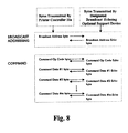
- FIG. 8 illustrates Broadcast Communications.
- Printer controller 10a first transmits a unique "broadcast address" on bus 13 (Fig. 2) of which all optional support devices receive and enters Broadcast Communications (as described above).
- the optional support device which had previously been designated the task of echoing all transmissions by printer controller 10a, echoes the broadcast address (Fig. 8) back to printer controller 10a.
- Figure 8 further illustrates commands broadcasted to all optional support devices of which the designated broadcast echoing optional support device is shown echoing the commands transmitted by printer controller 10a.
- printer controller 10a may choose not to designate one of the optional support devices as the optional support device to echo back printer controller 10a transmissions. In the alternate embodiment, the echoing shown in Fig. 8 does not occur.
- the "communications session” is a feature of the invention that pertains to situations in which printer controller 10a desires to transmit several commands in succession to one particular optional support device. Within the “communications session,” printer controller 10a does not transmit the device address before each successive command.
- the general format for a communications session is shown in Figure 9.
- the optional support device is addressed by printer controller 10a.
- the communications session is opened (begun) with a "Begin Communications Session" command transmitted by printer controller 10a.
- printer controller 10a transmits the desired sequence of commands to the optional support device.
- printer controller 10a terminates the communications session by transmitting an "End Communications Session" command.
- the End Communications Session command is received by the optional support device, the next command transmitted to that optional support device must be preceded by an address frame which contains the device address of that optional support device or the Broadcast Address.
- An advantage of being able to send several commands within a communications session is to improve the usage of bus 13 (Fig. 2) bandwidth, since the overhead of addressing the optional support device is spread over several commands. Thus the total transmission time for a set of commands, is less than would result if the device address were sent before each command transmitted to the optional support device.
- a feature of the invention is the communication interface error detection capability.
- the echo bytes specified in the Standard Communications Syntax allow printer controller 10a and optional support devices to detect certain transmission errors. Also, the specific UART hardware employed by printer controller 10a and the optional support devices provide additional transmission error detection capabilities.
- Bus 13 error detection capabilities included in the invention allow the detection of communication errors arising from, for example, but not limited to, intermittent signal connections and electrostatic discharges. The ability to detect transmission errors on bus 13 prevents corrupted data from causing unpredictable behavior of system 5. Communication interface transmission error detection on bus 13 is performed by both printer controller 10a and optional support devices.
- the UART of printer controller 10a has the capability to detect certain bus 13 transmission errors, such as framing errors. Whenever printer controller 10a detects a transmission error in a received frame, it aborts processing the current command, and then transmits an address frame containing the unique "Link Reset" address on bus 13. Upon receiving the Link Reset address, each optional support device aborts any command that it may be processing, and re-initializes its UART, communications protocol processing, and command interpreter to the state in which the optional support device is waiting to be addressed. Each given optional support device still responds to the same uniquely assigned address that it received from printer controller 10a during initialization, i.e., a Link Reset does not cause optional support devices to return to their trunkline address.
- a Link Reset does not cause optional support devices to return to their trunkline address.
- All optional support devices receive the Link Reset, since the programmable 9th data bit is set as part of the Link Reset frame transmitted.
- Each optional support device when processing a command or status response, must examine the programmable 9th data bit for all frames received from printer controller 10a to determine if a Link Reset has been transmitted.
- Printer controller 10a also has the capability to detect bus 13 transmission errors that corrupt the value of the information field in a frame received from an optional support device, after which printer controller 10a transmits the Link Reset. Printer controller 10a detects such transmission errors by examining the echo byte received from the optional support devices; i.e., the Device Address Echo, Command Op Code Echo, and Command Data Echo, which are shown in Fig. 6.
- printer controller 10a After transmitting the Device Address byte, the printer controller 10a compares the value of the Device Address Echo byte transmitted by the optional support device to the Device Address byte that was transmitted by printer controller 10a. If the two values differ, printer controller 10a determines that a transmission error has occurred and transmits the Link Reset. In a similar manner, printer controller 10a compares the Command Op Code byte transmitted to the resulting Command Op Code Echo byte received from the optional support device. If they are not identical, printer controller 10a likewise transmits the Link Reset. In a similar manner, printer controller 10a compares each Command Data byte transmitted to the resulting Command Data Echo byte received from the optional support device. If they are not identical, printer controller 10a transmits the Link Reset.
- Printer controller 10a does not examine any Response Data byte value for possible transmission errors. Transmission errors that corrupt a Response Data byte are detected and reported by the optional support device as described below. If printer controller 10a detects an error in the transmission of the End of Response byte, it transmits the Link Reset. Another instance in which printer controller 10a transmits the Link Reset is when any expected transmission from the optional support device is not received within a specified time.
- printer controller 10a utilizes these echoes to detect transmission errors in the same manner as described above, during broadcast communications.
- each optional support device has the capability to detect certain transmission errors on bus 13 (Fig. 2). Whenever an optional support device detects a transmission error in a received frame, the optional support device reports the occurrence of the error by setting the address indicator/alarm field (the programmable 9th data bit) in the next frame transmitted to printer controller 10a. The information field in that frame is the same as it would have been if no transmission error were being reported; i.e., no special information field value is transmitted by the optional support device for this situation. In addition to reporting the bus 13 transmission error to printer controller 10a, the optional support device aborts processing the command or status response in process. Printer controller 10a examines the programmable 9th data bit for every frame received from the optional support devices. When printer controller 10a recognizes that the optional support device has detected a transmission error on bus 13, printer controller 10a transmits a Link Reset.
- the optional support device also has the capability to detect bus 13 transmission errors that corrupt the value of the information field in a frame received from the printer controller 10a, after which the optional support device reports a transmission error on bus 13 to printer controller 10a by setting the programmable 9th data bit in the next frame transmitted to printer controller 10a.
- the addressed optional support device examines the Command Op Code byte value received from printer controller 10a. If the Command Op Code byte value is not a valid op code value, the optional support device reports that a transmission error has occurred. The addressed optional support device does not examine the Command Data byte value for possible bus 13 (Fig. 2) transmission errors.
- Transmission errors that corrupt a Command Data byte are detected by the printer controller 10a when it examines the corresponding Command Data Echo byte transmitted by the optional support device.
- the addressed optional support device examines the Start of Response byte value received from printer controller 10a. If the value is not identical to the predefined Start of Response byte value, the optional -support device reports that a transmission error has occurred in the manner described above. Likewise, the addressed optional support device compares the received Response Data #n Echo byte transmitted by a printer controller 10a to the corresponding Response Data #n byte that was transmitted to printer controller 10a. If the values are not identical, the optional support device reports that a transmission error has occurred.
- the optional support device previously designated by printer controller 10a to be the echoing device, detects and reports transmission errors during broadcast communications, in the same manner as described above.
Landscapes
- Engineering & Computer Science (AREA)
- General Engineering & Computer Science (AREA)
- Physics & Mathematics (AREA)
- General Physics & Mathematics (AREA)
- Theoretical Computer Science (AREA)
- Accessory Devices And Overall Control Thereof (AREA)
Applications Claiming Priority (2)
| Application Number | Priority Date | Filing Date | Title |
|---|---|---|---|
| US08/853,767 US6614545B1 (en) | 1997-05-09 | 1997-05-09 | Communication scheme for imaging systems including printers with intelligent options |
| US853767 | 1997-05-09 |
Publications (3)
| Publication Number | Publication Date |
|---|---|
| EP0881594A2 true EP0881594A2 (fr) | 1998-12-02 |
| EP0881594A3 EP0881594A3 (fr) | 2000-12-06 |
| EP0881594B1 EP0881594B1 (fr) | 2005-10-26 |
Family
ID=25316840
Family Applications (1)
| Application Number | Title | Priority Date | Filing Date |
|---|---|---|---|
| EP98303633A Expired - Lifetime EP0881594B1 (fr) | 1997-05-09 | 1998-05-08 | Un système d'impression avec des dispositifs optionnels connectés en série |
Country Status (7)
| Country | Link |
|---|---|
| US (2) | US6614545B1 (fr) |
| EP (1) | EP0881594B1 (fr) |
| JP (1) | JPH111050A (fr) |
| KR (1) | KR100518688B1 (fr) |
| CN (1) | CN1126024C (fr) |
| DE (1) | DE69832005T2 (fr) |
| TW (1) | TW461960B (fr) |
Families Citing this family (31)
| Publication number | Priority date | Publication date | Assignee | Title |
|---|---|---|---|---|
| US6332173B2 (en) | 1998-10-31 | 2001-12-18 | Advanced Micro Devices, Inc. | UART automatic parity support for frames with address bits |
| US6311235B1 (en) * | 1998-10-31 | 2001-10-30 | Advanced Micro Devices, Inc. | UART support for address bit on seven bit frames |
| DE19906867C1 (de) * | 1999-02-18 | 2000-07-06 | Weidmueller Interface | Verfahren und Vorrichtung zur seriellen Datenübertragung |
| JP2001184181A (ja) * | 1999-12-27 | 2001-07-06 | Canon Inc | 印刷処理方法及び記憶媒体 |
| US6760854B2 (en) * | 2000-01-15 | 2004-07-06 | Cirrus Logic, Inc. | Method and apparatus for handling a framing error at a serial interface by forcing invalid commands to be read upon determine the command is invalid |
| JP4593813B2 (ja) * | 2000-03-16 | 2010-12-08 | キヤノン株式会社 | 画像形成装置のオプション装置および画像形成装置並びに画像形成システム |
| US6516167B2 (en) | 2000-03-16 | 2003-02-04 | Canon Kabushiki Kaisha | Option apparatuses adapted to be connected to remote apparatus and image formation apparatus |
| WO2001077844A1 (fr) * | 2000-04-10 | 2001-10-18 | Fujitsu Limited | Systeme de traitement d'informations et serveur associe |
| DE60118302T2 (de) * | 2000-06-16 | 2006-08-24 | Seiko Epson Corp. | Drucker, der eine Steuerungsvorrichtung und ein Druckgerät umfasst |
| JP4801281B2 (ja) | 2001-05-31 | 2011-10-26 | 富士通株式会社 | 光パルス挿入装置 |
| US8699053B2 (en) * | 2002-01-24 | 2014-04-15 | Hewlett-Packard Development Company, L.P. | System and method for mobile printing from a desktop operating system using a portable computing device |
| JP3622733B2 (ja) * | 2002-03-07 | 2005-02-23 | ブラザー工業株式会社 | アドレス設定装置、プログラム |
| US20040192273A1 (en) * | 2003-01-02 | 2004-09-30 | Auyeung Al T. | Speed answers to voice prompts |
| JP2005100362A (ja) * | 2003-08-29 | 2005-04-14 | Canon Inc | プログラム書き換え可能な電子装置およびプログラム書き換え方法 |
| CN100485644C (zh) * | 2004-02-10 | 2009-05-06 | 上海新时达电气股份有限公司 | 自动分配串行总线设备地址分配器及其控制方法 |
| KR100555742B1 (ko) * | 2004-05-31 | 2006-03-03 | 삼성전자주식회사 | 화상형성기기의 용지이송장치 및 그 제어방법 |
| KR100613606B1 (ko) | 2004-06-25 | 2006-08-21 | 삼성전자주식회사 | 전송받은 본체의 사양정보를 이용하여 자신의 구동조건을설정하는 화상형성기기의 옵션장치 및 그 제어방법 |
| JP4478598B2 (ja) * | 2005-03-18 | 2010-06-09 | キヤノン株式会社 | 画像形成装置 |
| JP4546299B2 (ja) * | 2005-03-18 | 2010-09-15 | キヤノン株式会社 | 画像形成装置 |
| JP2006256275A (ja) * | 2005-03-18 | 2006-09-28 | Canon Inc | 装置および画像形成装置 |
| US7916318B2 (en) * | 2005-05-13 | 2011-03-29 | Canon Kabushiki Kaisha | Image forming system and image forming method |
| KR100740224B1 (ko) * | 2005-06-29 | 2007-07-18 | 삼성전자주식회사 | 화상형성장치 및 그 트레이와의 통신방법 |
| JP2007098940A (ja) * | 2005-09-08 | 2007-04-19 | Canon Inc | 画像形成システムおよびその制御方法 |
| US7614737B2 (en) * | 2005-12-16 | 2009-11-10 | Lexmark International Inc. | Method for identifying an installed cartridge |
| DE102005060601A1 (de) * | 2005-12-17 | 2007-06-21 | Dr. Johannes Heidenhain Gmbh | Verfahren zur Inbetriebnahme einer numerischen Steuerung für Werkzeug- oder Produktionsmaschinen |
| JP2008033709A (ja) * | 2006-07-31 | 2008-02-14 | Seiko Epson Corp | ソフトウェアの更新データを送信する方法及びシステム |
| DE102007052117A1 (de) * | 2007-10-30 | 2009-05-07 | Voith Patent Gmbh | Antriebsstrang, insbesondere für Lkw und Schienenfahrzeuge |
| JP5743391B2 (ja) * | 2009-09-24 | 2015-07-01 | キヤノン株式会社 | 制御装置および画像形成装置 |
| CN105223792B (zh) * | 2015-09-21 | 2019-01-22 | 珠海奔图电子有限公司 | 纸盒、图像形成装置以及为纸盒设置设备地址的方法 |
| TWI634017B (zh) | 2017-12-14 | 2018-09-01 | 虹光精密工業股份有限公司 | 具有識別紙匣模組功能之紙匣裝置 |
| WO2020132695A1 (fr) * | 2018-12-21 | 2020-06-25 | Avery Dennison Retail Information Services, Llc | Systèmes et procédés d'impression distribuée destinés à être utilisés avec un tri robotique automatisé |
Family Cites Families (27)
| Publication number | Priority date | Publication date | Assignee | Title |
|---|---|---|---|---|
| JPS6040051B2 (ja) * | 1976-01-19 | 1985-09-09 | ハネウエル・インコ−ポレ−テツド | プリンタ制御方式 |
| US4282583A (en) | 1977-06-10 | 1981-08-04 | Dataproducts Corporation | Microprogrammable processor control printer system |
| US4417304A (en) * | 1979-07-30 | 1983-11-22 | International Business Machines Corporation | Synchronous cycle steal mechanism for transferring data between a processor storage unit and a separate data handling unit |
| US4426166A (en) | 1982-10-14 | 1984-01-17 | Qume Corporation | Modular printer with coded plug compatible modules |
| US4710871A (en) * | 1982-11-01 | 1987-12-01 | Ncr Corporation | Data transmitting and receiving apparatus |
| US4556959A (en) | 1983-03-29 | 1985-12-03 | International Business Machines Corp. | Printer selection of options |
| US4686506A (en) * | 1983-04-13 | 1987-08-11 | Anico Research, Ltd. Inc. | Multiple connector interface |
| US4825404A (en) | 1985-11-27 | 1989-04-25 | Tektronix, Inc. | Interface system which generates configuration control signal and duplex control signal for automatically determining the configuration of removable modules |
| US4965771A (en) | 1986-08-18 | 1990-10-23 | Minolta Camera Kabushiki Kaisha | Printer controller for connecting a printer to an information processor having a different protocol from that of a printer |
| US5014193A (en) | 1988-10-14 | 1991-05-07 | Compaq Computer Corporation | Dynamically configurable portable computer system |
| US5418904A (en) * | 1988-11-08 | 1995-05-23 | Ricoh Company, Ltd. | Image forming system |
| US5056001A (en) | 1989-12-20 | 1991-10-08 | Ge Fanuc Automation North America, Inc. | Method for configuring an input/output module coupled to a programmable logic controller |
| JP3275261B2 (ja) | 1990-03-09 | 2002-04-15 | セイコーエプソン株式会社 | 情報処理装置 |
| FR2663137B1 (fr) | 1990-06-12 | 1994-07-29 | Sgs Thomson Microelectronics | Dispositif electronique de connexion. |
| DE69122668T2 (de) * | 1990-06-20 | 1997-03-13 | Canon Kk | Verfahren und Vorrichtung zur Bildverarbeitung |
| EP0491480B1 (fr) | 1990-12-17 | 1997-01-02 | Hewlett-Packard Company | Dispositif d'adressage d'un ordinateur |
| DE69230270T2 (de) | 1991-04-18 | 2000-04-20 | Canon K.K. | Kommunikationssteuereinheit |
| US5367640A (en) | 1991-04-30 | 1994-11-22 | Hewlett-Packard Company | System for configuring an input/output board in a computer |
| JP2661416B2 (ja) | 1991-06-29 | 1997-10-08 | ブラザー工業株式会社 | 印字システム |
| CA2075774C (fr) | 1991-08-27 | 2000-10-17 | Jeff D. Pipkins | Protocole pour interface parallele bidirectionnelle |
| US5299296A (en) * | 1991-10-17 | 1994-03-29 | Ricoh Company, Ltd. | Multi-function machine with interleaved job execution |
| US5467434A (en) | 1992-08-28 | 1995-11-14 | Xerox Corporation | Apparatus and method for determining printer option availability and representing conflict resolution in a combination of print job selections |
| US5428748A (en) | 1992-09-24 | 1995-06-27 | National Semiconductor Corporation | Method and apparatus for automatically configuring a computer peripheral |
| US5530897A (en) | 1993-10-01 | 1996-06-25 | International Business Machines Corporation | System for dynamic association of a variable number of device addresses with input/output devices to allow increased concurrent requests for access to the input/output devices |
| US5748483A (en) * | 1994-12-13 | 1998-05-05 | Check Technology Corporation | Printing system |
| JP3348331B2 (ja) * | 1995-04-21 | 2002-11-20 | ソニー株式会社 | 電子機器及びその動作モード制御方法 |
| US5761600A (en) * | 1995-07-20 | 1998-06-02 | Canon Kabushiki Kaisha | Sheet storage apparatus having plural sheet storage trays with variable distance |
-
1997
- 1997-05-09 US US08/853,767 patent/US6614545B1/en not_active Expired - Lifetime
- 1997-11-13 US US08/969,240 patent/US6028675A/en not_active Expired - Lifetime
-
1998
- 1998-05-07 KR KR1019980016356A patent/KR100518688B1/ko not_active Expired - Fee Related
- 1998-05-08 CN CN98107983.0A patent/CN1126024C/zh not_active Expired - Fee Related
- 1998-05-08 EP EP98303633A patent/EP0881594B1/fr not_active Expired - Lifetime
- 1998-05-08 DE DE69832005T patent/DE69832005T2/de not_active Expired - Fee Related
- 1998-05-11 JP JP14652998A patent/JPH111050A/ja not_active Withdrawn
- 1998-07-20 TW TW087107164A patent/TW461960B/zh not_active IP Right Cessation
Also Published As
| Publication number | Publication date |
|---|---|
| US6614545B1 (en) | 2003-09-02 |
| EP0881594B1 (fr) | 2005-10-26 |
| US6028675A (en) | 2000-02-22 |
| KR100518688B1 (ko) | 2006-01-12 |
| DE69832005T2 (de) | 2006-07-13 |
| JPH111050A (ja) | 1999-01-06 |
| TW461960B (en) | 2001-11-01 |
| KR19980086839A (ko) | 1998-12-05 |
| CN1206140A (zh) | 1999-01-27 |
| EP0881594A3 (fr) | 2000-12-06 |
| DE69832005D1 (de) | 2005-12-01 |
| CN1126024C (zh) | 2003-10-29 |
Similar Documents
| Publication | Publication Date | Title |
|---|---|---|
| EP0881594B1 (fr) | Un système d'impression avec des dispositifs optionnels connectés en série | |
| US5204669A (en) | Automatic station identification where function modules automatically initialize | |
| US5247623A (en) | Automatic multiple personal computer/computer printer connecting system | |
| US5537558A (en) | Apparatus and method for communicating multiple devices through one PCMCIA interface | |
| US20120212783A1 (en) | Image forming apparatus and a communication method with trays thereof | |
| JPH02136274A (ja) | 画像形成システム | |
| EP0506594A2 (fr) | Interface parallèle bidirectionnel pour imprimante | |
| JPH02120066A (ja) | 画像形成システム | |
| US6903832B2 (en) | Output control apparatus, output control method and memory medium storing program readable by computer | |
| GB2128367A (en) | Photocopying machine | |
| JP3012252B2 (ja) | 画像形成システム | |
| CN110704341A (zh) | 一种串口单线升级代码的装置及其方法 | |
| US5163137A (en) | Copying system with a dual trunk serial communication system using an acknowledge line | |
| US5822522A (en) | System for transferring data through a communication interface using control information in request data for controlling data receiving rates independent of the CPU | |
| GB2308208A (en) | Controlling the use of logical communication channels | |
| JP2841858B2 (ja) | プリンタの制御装置 | |
| JPH088935A (ja) | 増設ユニットインタフェース | |
| JPH02231178A (ja) | 画像形成システム | |
| JPH10171747A (ja) | 連設型装置 | |
| JPH0374716A (ja) | 主従装置間の通信方式 | |
| JPH10224425A (ja) | シリアル通信システム | |
| JP2001353936A (ja) | 印刷装置 | |
| JPH05732B2 (fr) | ||
| JPH02236615A (ja) | 画像形成システム | |
| JP2000203127A (ja) | パラレルデ―タ通信装置及びその装置を備えた画像形成装置 |
Legal Events
| Date | Code | Title | Description |
|---|---|---|---|
| PUAI | Public reference made under article 153(3) epc to a published international application that has entered the european phase |
Free format text: ORIGINAL CODE: 0009012 |
|
| AK | Designated contracting states |
Kind code of ref document: A2 Designated state(s): DE FR GB IT |
|
| AX | Request for extension of the european patent |
Free format text: AL;LT;LV;MK;RO;SI |
|
| PUAL | Search report despatched |
Free format text: ORIGINAL CODE: 0009013 |
|
| AK | Designated contracting states |
Kind code of ref document: A3 Designated state(s): AT BE CH CY DE DK ES FI FR GB GR IE IT LI LU MC NL PT SE |
|
| AX | Request for extension of the european patent |
Free format text: AL;LT;LV;MK;RO;SI |
|
| RIC1 | Information provided on ipc code assigned before grant |
Free format text: 7G 06K 15/00 A, 7B 41J 29/00 B, 7G 06F 13/37 B |
|
| 17P | Request for examination filed |
Effective date: 20010601 |
|
| AKX | Designation fees paid |
Free format text: DE FR GB IT |
|
| 17Q | First examination report despatched |
Effective date: 20040727 |
|
| GRAP | Despatch of communication of intention to grant a patent |
Free format text: ORIGINAL CODE: EPIDOSNIGR1 |
|
| GRAS | Grant fee paid |
Free format text: ORIGINAL CODE: EPIDOSNIGR3 |
|
| GRAA | (expected) grant |
Free format text: ORIGINAL CODE: 0009210 |
|
| AK | Designated contracting states |
Kind code of ref document: B1 Designated state(s): DE FR GB IT |
|
| REG | Reference to a national code |
Ref country code: GB Ref legal event code: FG4D |
|
| REF | Corresponds to: |
Ref document number: 69832005 Country of ref document: DE Date of ref document: 20051201 Kind code of ref document: P |
|
| ET | Fr: translation filed | ||
| PLBE | No opposition filed within time limit |
Free format text: ORIGINAL CODE: 0009261 |
|
| STAA | Information on the status of an ep patent application or granted ep patent |
Free format text: STATUS: NO OPPOSITION FILED WITHIN TIME LIMIT |
|
| 26N | No opposition filed |
Effective date: 20060727 |
|
| PGFP | Annual fee paid to national office [announced via postgrant information from national office to epo] |
Ref country code: DE Payment date: 20070702 Year of fee payment: 10 |
|
| PGFP | Annual fee paid to national office [announced via postgrant information from national office to epo] |
Ref country code: GB Payment date: 20070525 Year of fee payment: 10 |
|
| PGFP | Annual fee paid to national office [announced via postgrant information from national office to epo] |
Ref country code: IT Payment date: 20070525 Year of fee payment: 10 |
|
| PGFP | Annual fee paid to national office [announced via postgrant information from national office to epo] |
Ref country code: FR Payment date: 20070517 Year of fee payment: 10 |
|
| GBPC | Gb: european patent ceased through non-payment of renewal fee |
Effective date: 20080508 |
|
| REG | Reference to a national code |
Ref country code: FR Ref legal event code: ST Effective date: 20090119 |
|
| PG25 | Lapsed in a contracting state [announced via postgrant information from national office to epo] |
Ref country code: FR Free format text: LAPSE BECAUSE OF NON-PAYMENT OF DUE FEES Effective date: 20080602 Ref country code: DE Free format text: LAPSE BECAUSE OF NON-PAYMENT OF DUE FEES Effective date: 20081202 |
|
| PG25 | Lapsed in a contracting state [announced via postgrant information from national office to epo] |
Ref country code: GB Free format text: LAPSE BECAUSE OF NON-PAYMENT OF DUE FEES Effective date: 20080508 |
|
| PG25 | Lapsed in a contracting state [announced via postgrant information from national office to epo] |
Ref country code: IT Free format text: LAPSE BECAUSE OF NON-PAYMENT OF DUE FEES Effective date: 20080508 |