EP0882247B1 - Konfokales mikroskop - Google Patents
Konfokales mikroskop Download PDFInfo
- Publication number
- EP0882247B1 EP0882247B1 EP97905236A EP97905236A EP0882247B1 EP 0882247 B1 EP0882247 B1 EP 0882247B1 EP 97905236 A EP97905236 A EP 97905236A EP 97905236 A EP97905236 A EP 97905236A EP 0882247 B1 EP0882247 B1 EP 0882247B1
- Authority
- EP
- European Patent Office
- Prior art keywords
- confocal
- light
- specimen
- image
- microscope
- Prior art date
- Legal status (The legal status is an assumption and is not a legal conclusion. Google has not performed a legal analysis and makes no representation as to the accuracy of the status listed.)
- Expired - Lifetime
Links
Images


Classifications
-
- G—PHYSICS
- G02—OPTICS
- G02B—OPTICAL ELEMENTS, SYSTEMS OR APPARATUS
- G02B21/00—Microscopes
- G02B21/0004—Microscopes specially adapted for specific applications
- G02B21/002—Scanning microscopes
- G02B21/0024—Confocal scanning microscopes (CSOMs) or confocal "macroscopes"; Accessories which are not restricted to use with CSOMs, e.g. sample holders
- G02B21/0036—Scanning details, e.g. scanning stages
- G02B21/004—Scanning details, e.g. scanning stages fixed arrays, e.g. switchable aperture arrays
-
- G—PHYSICS
- G02—OPTICS
- G02B—OPTICAL ELEMENTS, SYSTEMS OR APPARATUS
- G02B21/00—Microscopes
- G02B21/0004—Microscopes specially adapted for specific applications
- G02B21/002—Scanning microscopes
- G02B21/0024—Confocal scanning microscopes (CSOMs) or confocal "macroscopes"; Accessories which are not restricted to use with CSOMs, e.g. sample holders
- G02B21/008—Details of detection or image processing, including general computer control
- G02B21/0084—Details of detection or image processing, including general computer control time-scale detection, e.g. strobed, ultra-fast, heterodyne detection
Definitions
- the present invention relates to a confocal microscope and in particular a confocal microscope which enables real-time imaging to be performed.
- FIG. 1 A schematic diagram of a known reflection confocal scanning microscope such as that described in Confocal Microscopy by Tony Wilson, Academic Press (1990) is shown in Figure 1.
- the microscope consists of a laser light source 1 from which laser light passes to a lens 2 for generating a diffraction limited spot of light.
- the spot of light is reflected from an object 3 which is being scanned and the reflected light is extracted 4 and then passed to a photodetector 5.
- the reflected light intensity is separately measured by the photodetector 5 for each scanned point on the object 3.
- the signals generated by the photodetector 5 are then used to intensity modulate a TV screen 6 which is scanned in synchronism with the scanning spot of light.
- Known confocal microscope systems such as the one described above have the disadvantage that very bright light sources are required and this usually necessitates the use of lasers. Also, as the microscope images by scanning a spot of light over the object, real-time imaging could not easily be performed.
- optical sectioning and lateral resolution achieved with the confocal microscope described above arises as a result of the illumination and imaging systems being arranged whereby only light which has originated from a specific position in the source plane is detected at the equivalent position in the detector plane.
- this is described as the source and detector distributions being delta correlated and with most known confocal microscopes is achieved by employing a single point source and point detector.
- the present invention seeks to overcome the disadvantages described above with respect to known confocal microscopes whilst retaining the advantages of optical sectioning and lateral resolution and seeks to provide a confocal microscope capable of performing real-time imaging with a significantly improved light budget.
- the present invention provides a confocal microscope having means for directing light to a specimen to be imaged; at least one mask for encoding light incident on the specimen and for decoding light from a plurality of regions of the specimen simultaneously thereby generating a confocal image of the specimen superimposed on a non-confocal image; and means for detecting decoded light from the specimen.
- means for separating the confocal image from the detected light is additionally provided.
- the requirement that the source and detector masks are substantially delta correlated no longer applies, and hence masks with greater light efficiency may be employed in comparison with known confocal systems.
- the confocal image is formed simultaneously with a plurality of regions, preferably all, of the confocal image, real-time confocal imaging of a specimen can be performed.
- the non-confocal image is substantially a conventional image.
- the non-confocal image though may include de-focused images and other imaging artefacts.
- the confocal microscope is a reflection mode microscope and a single mask is provided both for encoding light incident on the specimen to be imaged and for decoding light from the specimen.
- the confocal microscope may be a transmission mode microscope whereby two separate matched masks are provided.
- the mask is in the form of at least one spatial light modulator programmed to code and decode the incident and emergent light.
- the spatial light modulator may be arranged to produce predetermined intensity modulation or polarisation modulation of incident light.
- the mask is in the form of at least one rotating disk having a plurality of predetermined portions capable of varying at least one characteristic of incident light to different extents.
- the predetermined portions may be capable of varying the intensity, phase or polarisation of incident light or any combination thereof.
- the means for detecting the light from the specimen and for separating out the confocal image may be in the form of an array of photodetectors connected to a programmed computer.
- the confocal image may be extracted with a polarising beam splitter in combination with one or more photodetector arrays or other camera device.
- the mask encodes the light incident on the specimen using finite length binary time sequences.
- the combined confocal and conventional image may then be obtained by time averaging the detected image over the finite length of the sequence.
- the confocal microscope shown in Figure 2 consists of a light source 10, a source mask 11 and a detector mask 12 either side of the specimen to be imaged 13 and a CCD camera 14 beyond the detector mask 12.
- the light source 10 illuminates the source mask 11 which is then imaged onto the specimen by lens system 15 located between the source mask 11 and the specimen 13.
- Lens system 16 located between the specimen 13 and the detector mask 12 images the specimen onto the detector mask 12.
- the camera 14 images the detector mask 12.
- the source and detector masks 11,12 are replaced by a single aperture mask 17 and a beam splitter 18 positioned between the light source 10 and the aperture mask 17 is provided for directing the reflected light to the camera 14.
- each detector pixel acts as a matched filter to its corresponding source pixel.
- the desired correlation between the source and detector distributions may be achieved.
- each source pixel may be modulated with a unique time sequence and the same sequence used as a reference signal for matched filtering at the detector.
- the sequence presented to each pixel should have zero cross-correlation with that presented to any other pixel and an approximation to this is the use of independent random binary sequences for each pixel.
- An SLM consists of an array of pixels in which each pixel is individually addressable.
- One of the advantages of using the SLM is the fast frame rate which enables real-time imaging.
- One particular implementation of an SLM consists of a ferroelectric liquid crystal device (FLCSLM) in which each pixel of the SLM acts as a birefringent retardation plate which can be switched in the plane of the SLM between two orientations of its optical axes.
- FLCSLM ferroelectric liquid crystal device
- the FLCSLM With the FLCSLM located between crossed polarising filters aligned along the corresponding optical axes of one of the stable states of the FLCSLM, the FLCSLM can be used as an intensity modulator. With this arrangement each individually addressable pixel of the FLCSLM transmits light in one of the states of the FLCSLM and is opaque to light in the other state of the FLCSLM and in this way the FLCSLM acts as a programmable spatial intensity modulator. This though has the disadvantage that light is lost due to attenuation in the opaque pixels.
- the light incident on the FLCSLM is arranged to be linearly polarised along the bisector of the principal axes of the two FLCSLM states whereby the FLCSLM functions as a polarisation modulator.
- the FLCSLM functions as a polarisation modulator.
- the camera positioned behind the polarising beam splitter will therefore only register light which passed through the same pixel to and from the specimen.
- the camera will also register light which passed through a different pixel from the specimen which is in the same state as the pixel through which it passed to the specimen.
- This will result in a conventional image being superimposed on the confocal image.
- the conventional image may be subtracted electronically from the combined image to form a pure confocal image of the specimen. If, however, an image is formed using the light rejected by the polarising beam splitter then the contrast of the confocal part of the image is reversed. It is therefore possible to obtain the confocal image in real-time merely by subtracting the images obtained at both outputs of the polarising beam splitter.
- the polarisation approach has the advantage that less light is lost than in the arrangement where the FLCSLM is arranged as an intensity modulator.
- An alternative implementation of an SLM is a digital micromirror device (DMD) which consists of a large array of very small mirrors, each of which can be individually addressed to control deflection of an incident light beam.
- DMD digital micromirror device
- the DMD is particularly suited to use as an SLM in reflection mode with the orientation of the individual mirrors being encoded in a manner similar to that described above with respect to the FLCSLM.
- the aperture mask may be in the form of a spinning disc.
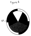
- the spinning disc may be impressed with the sequences or modulation codes photolithographically and an example of a suitable mask for use in the confocal microscope is shown in Figure 4.
- blank sectors are provided on the disk to provide the conventional image.
- the camera and the electronics are then synchronised with the disc rotation to enable the subtraction to be performed.
- the spinning disk shown in Figure 4 uses intensity modulation for the encoding in a further alternative the spinning disk may be arranged to perform polarisation modulation.
- the image produced is a combined confocal and conventional image with the confocal image appearing as a bright region superimposed on the ordinary image.
- the absence of the blank sectors means that the conventional image cannot be selectively extracted through appropriate synchronisation as in the previous example.
- This image is particularly useful for navigating around a specimen to identify a specific region of interest. In this case, the image is used in its combined form without extraction of the confocal image.
- the disc may be encoded with a regular, close packed pattern for example in the form of a checker-board or uniform lines of equal spacing.
- the disc is then illuminated with incoherent light a combined non-confocal and confocal image is obtained from which the confocal image can be extracted in the manner described.
- coherent illumination may be employed when fluorescent imaging is being performed.
- the confocal image can be recalled using an alternative procedure in which the image from a single camera consists of the conventional image l o on even lines and the combined conventional and confocal image I 0 +I c on odd lines.
- the confocal image may be easily extracted by low pass filtering of the image IS. In practice this is performed by the use of fast Fourier transforms.
- the conventional image it is also possible for the conventional image to be extracted. In this way both confocal and conventional images may be generated simultaneously.
- the image quality and the light budget are independent of one another.
- the image quality is dependent on the sophistication and length of the code sequences and the light budget is determined on the basis of the modulation employed.
- the confocal microscope enables real-time imaging to be performed and this includes all three-dimensional modes of operation. Direct viewing of the composite image can be performed and as shown in Figure 5 conventional microscopes may be easily converted to generate confocal images as desired.
- a conventional microscope comprising an eye piece 20, a tube lens 21, a beam splitter 22, an objective lens 23 and a light source 24.
- the microscope usually operates in reflective mode with the specimen 13 located beyond the objective lens 23.
- a confocal attachment 25 is provided between the beam splitter 22 and the objective lens 23.
- the confocal attachment 25 includes two lens systems 26,27 which are positioned one either side of an aperture mask 28 which is encoded in the same manner as described above so that a combined confocal and conventional image is obtained.
Landscapes
- Physics & Mathematics (AREA)
- Chemical & Material Sciences (AREA)
- Analytical Chemistry (AREA)
- General Physics & Mathematics (AREA)
- Optics & Photonics (AREA)
- Engineering & Computer Science (AREA)
- Computer Vision & Pattern Recognition (AREA)
- General Engineering & Computer Science (AREA)
- Microscoopes, Condenser (AREA)
- Investigating, Analyzing Materials By Fluorescence Or Luminescence (AREA)
- Dental Preparations (AREA)
Claims (15)
- Konfokales Mikroskop, umfassend: eine Einrichtung, um Licht zu einem Objekt zu lenken; mindestens eine zusammengesetzte Bildmaske, um auf eine Mehrzahl von Bereichen des Objekts einfallendes Licht zu kodieren und um gleichzeitig Licht aus der Mehrzahl von Bereichen des Objekts zu dekodieren, wodurch das dekodierte Licht ein konfokales Bild erzeugt, das einem nicht-konfokalen Bild überlagert ist; eine Einrichtung, um dekodiertes Licht aus dem Objekt zu erfassen; und eine Ausschleusungseinrichtung, um das konfokale Bild des Objekts vom erfassten Licht zu trennen.
- Konfokales Mikroskop nach Anspruch 1, bei dem die mindestens eine zusammengesetzte Bildmaske Licht aus dem Objekt dekodiert, um ein zusammengesetztes Bild zu erzeugen, das ein konfokales Bild ist, welches einem konventionellen Bild überlagert ist.
- Konfokales Mikroskop nach einem der vorangehenden Ansprüche, bei dem die mindestens eine zusammengesetzte Bildmaske angepasst ist, um Licht unter Verwendung von binären Zeitsequenzen finiter Länge zu kodieren und zu dekodieren.
- Konfokales Mikroskop nach Anspruch 3, bei dem die Ausschleusungseinrichtung eine Zeitmittelungsvorrichtung umfasst, um das erfasste Licht über die finite Länge der Sequenzen zu mitteln.
- Konfokales Mikroskop nach einem der vorangehenden Ansprüche, bei dem die mindestens eine zusammengesetzte Bildmaske ein räumlicher Lichtmodulator ist.
- Konfokales Mikroskop nach Anspruch 5, bei dem der räumliche Lichtmodulator eine digitale Mikrospiegelvorrichtung ist.
- Konfokales Mikroskop nach einem der Ansprüche 1 bis 4, bei dem die mindestens eine zusammengesetzte Bildmaske eine kodierte drehbare Scheibe ist.
- Konfokales Mikroskop nach Anspruch 7, bei dem die kodierte drehbare Scheibe im Wesentlichen durchsichtige Bereiche einschließt, die es ermöglichen, ein konventionelles Bild sowie das konfokale Bild auszuschleusen.
- Konfokales Mikroskop nach einem der vorangehenden Ansprüche, bei dem eine einzige Maske vorgesehen ist, und das Mikroskop angeordnet ist, um im Reflexionsmodus zu arbeiten.
- Konfokales Mikroskop nach einem der Ansprüche 1 bis 8, bei dem mindestens zwei Masken vorgesehen sind, und das Mikroskop angeordnet ist, um im Durchstrahlungsmodus zu arbeiten.
- Konfokales Mikroskop nach einem der vorangehenden Ansprüche, bei dem die mindestens eine zusammengesetzte Bildmaske unter Verwendung von Intensitätsmodulation kodiert ist.
- Konfokales Mikroskop nach einem der Ansprüche 1 bis 10, bei dem die mindestens eine zusammengesetzte Bildmaske unter Verwendung von Polarisationsmodulation kodiert ist.
- Konfokales Mikroskop nach einem der Ansprüche 1 bis 10, bei dem die mindestens eine zusammengesetzte Bildmaske unter Verwendung von Phasenmodulation kodiert ist.
- Konfokales Mikroskop nach einem der vorangehenden Ansprüche, bei dem die Einrichtung zum Erfassen von dekodiertem Licht ein Array von lichtempfindlichen Vorrichtungen umfasst.
- Mikroskopzubehör, umfassend mindestens eine zusammengesetzte Bildmaske, um auf eine Mehrzahl von Bereichen eines Objekts einfallendes Licht zu kodieren und um gleichzeitig Licht aus der Mehrzahl von Bereichen des Objekts zu dekodieren, wodurch das dekodierte Licht ein konfokales Bild erzeugt, das einem nicht-konfokalen Bild überlagert ist, sowie eine Einrichtung, um Licht zu und aus der Maske zu lenken, wobei das Zubehör zur Implementierung in einem konventionellen Mikroskop angepasst ist.
Applications Claiming Priority (3)
| Application Number | Priority Date | Filing Date | Title |
|---|---|---|---|
| GBGB9603788.2A GB9603788D0 (en) | 1996-02-22 | 1996-02-22 | Confocal microscope |
| GB9603788 | 1996-02-22 | ||
| PCT/GB1997/000490 WO1997031282A1 (en) | 1996-02-22 | 1997-02-21 | Confocal microscope |
Publications (2)
| Publication Number | Publication Date |
|---|---|
| EP0882247A1 EP0882247A1 (de) | 1998-12-09 |
| EP0882247B1 true EP0882247B1 (de) | 2001-04-11 |
Family
ID=10789235
Family Applications (1)
| Application Number | Title | Priority Date | Filing Date |
|---|---|---|---|
| EP97905236A Expired - Lifetime EP0882247B1 (de) | 1996-02-22 | 1997-02-21 | Konfokales mikroskop |
Country Status (10)
| Country | Link |
|---|---|
| US (1) | US6144489A (de) |
| EP (1) | EP0882247B1 (de) |
| JP (1) | JP4049393B2 (de) |
| AT (1) | ATE200585T1 (de) |
| AU (1) | AU1885997A (de) |
| CA (1) | CA2246698C (de) |
| DE (1) | DE69704554T2 (de) |
| ES (1) | ES2156364T3 (de) |
| GB (1) | GB9603788D0 (de) |
| WO (1) | WO1997031282A1 (de) |
Cited By (1)
| Publication number | Priority date | Publication date | Assignee | Title |
|---|---|---|---|---|
| DE102012007045A1 (de) | 2012-04-05 | 2013-10-10 | Carl Zeiss Microscopy Gmbh | Vorrichtung und Verfahren zur Mikroskopie |
Families Citing this family (45)
| Publication number | Priority date | Publication date | Assignee | Title |
|---|---|---|---|---|
| ATE236412T1 (de) * | 1997-10-22 | 2003-04-15 | Max Planck Gesellschaft | Programmierbares räumlich lichtmoduliertes mikroskop und mikroskopieverfahren |
| JP4372996B2 (ja) | 1997-10-29 | 2009-11-25 | ディジタル オプティカル イメージング コーポレイション | 空間的に光変調された顕微鏡法に関する装置及び方法 |
| DE69730030T2 (de) * | 1997-11-17 | 2005-07-21 | MAX-PLANCK-Gesellschaft zur Förderung der Wissenschaften e.V. | Konfokales Spektroskopiesystem und -verfahren |
| GB9807832D0 (en) | 1998-04-09 | 1998-06-10 | Isis Innovation | Imaging apparatus |
| JP3670839B2 (ja) | 1998-05-18 | 2005-07-13 | オリンパス株式会社 | 共焦点顕微鏡 |
| DE19824460A1 (de) * | 1998-05-30 | 1999-12-02 | Zeiss Carl Jena Gmbh | Anordnung und Verfahren zur mikroskopischen Erzeugung von Objektbildern |
| GB9901365D0 (en) * | 1999-01-22 | 1999-03-10 | Isis Innovations Ltd | Confocal microscopy apparatus and method |
| DE19908883A1 (de) | 1999-03-02 | 2000-09-07 | Rainer Heintzmann | Verfahren zur Erhöhung der Auflösung optischer Abbildung |
| US6426835B1 (en) | 1999-03-23 | 2002-07-30 | Olympus Optical Co., Ltd. | Confocal microscope |
| DE19960583A1 (de) * | 1999-12-15 | 2001-07-05 | Evotec Biosystems Ag | Verfahren und Vorrichtung zur Mikroskopie |
| AU3609601A (en) | 2000-03-06 | 2001-09-17 | Olympus Optical Co., Ltd. | Pattern forming member applied to sectioning image observing device and sectioning image observing device using it |
| EP1383018B1 (de) * | 2001-04-27 | 2009-06-03 | Citizen Holdings Co., Ltd. | Automatische drehmaschine und verfahren zu ihrer steuerung und einrichtung zu ihrer steuerung |
| WO2003025656A1 (en) * | 2001-09-03 | 2003-03-27 | Kabushiki Kaisha Hayashi Soken | Digital control scanning method and apparatus |
| US6885492B2 (en) * | 2001-11-08 | 2005-04-26 | Imaginative Optics, Inc. | Spatial light modulator apparatus |
| US7508608B2 (en) | 2004-11-17 | 2009-03-24 | Illumina, Inc. | Lithographically fabricated holographic optical identification element |
| US7619819B2 (en) | 2002-08-20 | 2009-11-17 | Illumina, Inc. | Method and apparatus for drug product tracking using encoded optical identification elements |
| US7441703B2 (en) | 2002-08-20 | 2008-10-28 | Illumina, Inc. | Optical reader for diffraction grating-based encoded optical identification elements |
| EP1575707A1 (de) | 2002-09-12 | 2005-09-21 | Cyvera Corporation | Verfahren und vorrichtung zur ausrichtung von länglichen mikroperlen zu deren untersuchung |
| AU2003270726A1 (en) | 2002-09-12 | 2004-04-30 | Cidra Corporation | Diffraction grating-based encoded micro-particles for multiplexed experiments |
| US7092160B2 (en) | 2002-09-12 | 2006-08-15 | Illumina, Inc. | Method of manufacturing of diffraction grating-based optical identification element |
| US6844927B2 (en) * | 2002-11-27 | 2005-01-18 | Kla-Tencor Technologies Corporation | Apparatus and methods for removing optical abberations during an optical inspection |
| US8081792B2 (en) | 2003-08-20 | 2011-12-20 | Illumina, Inc. | Fourier scattering methods for encoding microbeads and methods and apparatus for reading the same |
| DE602004024464D1 (de) | 2003-07-04 | 2010-01-14 | Vincent Lauer | Bildgebungsvorrichtung für konfokale Mikroskopie mit Bildsubstraktion |
| US7433123B2 (en) | 2004-02-19 | 2008-10-07 | Illumina, Inc. | Optical identification element having non-waveguide photosensitive substrate with diffraction grating therein |
| JP4425098B2 (ja) * | 2004-09-06 | 2010-03-03 | 浜松ホトニクス株式会社 | 蛍光顕微鏡および蛍光相関分光解析装置 |
| US7602952B2 (en) | 2004-11-16 | 2009-10-13 | Illumina, Inc. | Scanner having spatial light modulator |
| US7604173B2 (en) | 2004-11-16 | 2009-10-20 | Illumina, Inc. | Holographically encoded elements for microarray and other tagging labeling applications, and method and apparatus for making and reading the same |
| US7623624B2 (en) | 2005-11-22 | 2009-11-24 | Illumina, Inc. | Method and apparatus for labeling using optical identification elements characterized by X-ray diffraction |
| US7830575B2 (en) | 2006-04-10 | 2010-11-09 | Illumina, Inc. | Optical scanner with improved scan time |
| EP2016456A4 (de) * | 2006-04-20 | 2010-08-25 | Xceed Imaging Ltd | Durchweg optisches system und verfahren zur bereitstellung einer vergrösserten schärfentiefe bei der abbildung |
| US7460248B2 (en) * | 2006-05-15 | 2008-12-02 | Carestream Health, Inc. | Tissue imaging system |
| DE102006027836B4 (de) | 2006-06-16 | 2020-02-20 | Carl Zeiss Microscopy Gmbh | Mikroskop mit Autofokuseinrichtung |
| EP2434325A1 (de) * | 2006-12-22 | 2012-03-28 | Nikon Corporation | Konfokales Laser-Scanning-Mikroskop |
| US8228561B2 (en) * | 2007-03-30 | 2012-07-24 | Xerox Corporation | Method and system for selective bitmap edge smoothing |
| US8368959B2 (en) | 2009-05-18 | 2013-02-05 | Xerox Corporation | Method and system for selective smoothing of halftoned objects using bitmap encoding |
| WO2011136857A2 (en) * | 2010-01-06 | 2011-11-03 | Trustees Of Boston University | Correlation confocal microscope |
| DE102011013613A1 (de) * | 2010-10-01 | 2012-04-05 | Carl Zeiss Microimaging Gmbh | Mikroskop und Mikroskopierverfahren |
| US8797601B2 (en) | 2012-03-22 | 2014-08-05 | Xerox Corporation | Method and system for preserving image quality in an economy print mode |
| DE102012208869A1 (de) | 2012-05-25 | 2013-11-28 | Carl Zeiss Microscopy Gmbh | Lichtrastermikroskop und Mikroskopierverfahren |
| DE102013208872B4 (de) | 2013-05-14 | 2023-08-17 | Carl Zeiss Microscopy Gmbh | Verfahren zur Erzeugung eines Bildes einer Probe |
| DE102014004249A1 (de) * | 2014-03-24 | 2015-09-24 | Carl Zeiss Microscopy Gmbh | Konfokales Mikroskop mit Aperturkorrelation |
| HU231246B1 (hu) | 2015-08-31 | 2022-05-28 | 3Dhistech Kft | Konfokális elvû tárgylemez szkenner |
| DE102017105719A1 (de) | 2017-03-16 | 2018-09-20 | Carl Zeiss Microscopy Gmbh | Multi-Pinhole-Lichtrastermikroskop und -mikroskopieverfahren |
| DE102018210606B4 (de) | 2018-06-28 | 2025-10-02 | Carl Zeiss Microscopy Gmbh | Mikroskopisches Abbildungsverfahren unter Verwendung eines Korrekturfaktors |
| JP7654777B2 (ja) | 2020-08-25 | 2025-04-01 | オーロックス リミテッド | 顕微鏡 |
Family Cites Families (8)
| Publication number | Priority date | Publication date | Assignee | Title |
|---|---|---|---|---|
| US4806004A (en) * | 1987-07-10 | 1989-02-21 | California Institute Of Technology | Scanning microscopy |
| EP0339061B1 (de) * | 1987-09-24 | 1995-03-29 | Washington University | Konzept und umwandlungssatz eines standardmikroskops in ein mikroskop mit gemeinsamem brennpunkt und epi-beleuchtung mit einzelöffnung |
| US5235457A (en) * | 1987-09-24 | 1993-08-10 | Washington University | Kit for converting a standard microscope into a single aperture confocal scanning epi-illumination microscope |
| GB9014570D0 (en) * | 1990-06-29 | 1990-08-22 | Dixon Arthur E | Method for transmitted-light and reflected-light imaging |
| DE4023292A1 (de) * | 1990-07-21 | 1992-01-23 | Leica Lasertechnik | Anordnung zur simultanen konfokalen bilderzeugung |
| DE59107758D1 (de) * | 1990-11-10 | 1996-06-05 | Groskopf Rudolf Dr Ing | Optische Abtastvorrichtung mit konfokalem Strahlengang, in der Lichtquellen- und Detektormatrix verwendet werden |
| US5386317A (en) * | 1992-05-13 | 1995-01-31 | Prometrix Corporation | Method and apparatus for imaging dense linewidth features using an optical microscope |
| US5587832A (en) * | 1993-10-20 | 1996-12-24 | Biophysica Technologies, Inc. | Spatially light modulated confocal microscope and method |
-
1996
- 1996-02-22 GB GBGB9603788.2A patent/GB9603788D0/en active Pending
-
1997
- 1997-02-21 AT AT97905236T patent/ATE200585T1/de active
- 1997-02-21 US US09/125,625 patent/US6144489A/en not_active Expired - Lifetime
- 1997-02-21 CA CA002246698A patent/CA2246698C/en not_active Expired - Lifetime
- 1997-02-21 ES ES97905236T patent/ES2156364T3/es not_active Expired - Lifetime
- 1997-02-21 EP EP97905236A patent/EP0882247B1/de not_active Expired - Lifetime
- 1997-02-21 DE DE69704554T patent/DE69704554T2/de not_active Expired - Lifetime
- 1997-02-21 JP JP52990397A patent/JP4049393B2/ja not_active Expired - Lifetime
- 1997-02-21 AU AU18859/97A patent/AU1885997A/en not_active Abandoned
- 1997-02-21 WO PCT/GB1997/000490 patent/WO1997031282A1/en not_active Ceased
Cited By (4)
| Publication number | Priority date | Publication date | Assignee | Title |
|---|---|---|---|---|
| DE102012007045A1 (de) | 2012-04-05 | 2013-10-10 | Carl Zeiss Microscopy Gmbh | Vorrichtung und Verfahren zur Mikroskopie |
| WO2013149731A1 (de) | 2012-04-05 | 2013-10-10 | Carl Zeiss Microscopy Gmbh | Vorrichtung und verfahren zur mikroskopie |
| US9494782B2 (en) | 2012-04-05 | 2016-11-15 | Carl Zeiss Microscopy Gmbh | Device and method for microscopy using light with differing physical properties |
| DE102012007045B4 (de) | 2012-04-05 | 2023-03-16 | Carl Zeiss Microscopy Gmbh | Vorrichtung und Verfahren zur Mikroskopie |
Also Published As
| Publication number | Publication date |
|---|---|
| JP4049393B2 (ja) | 2008-02-20 |
| US6144489A (en) | 2000-11-07 |
| WO1997031282A1 (en) | 1997-08-28 |
| ATE200585T1 (de) | 2001-04-15 |
| EP0882247A1 (de) | 1998-12-09 |
| DE69704554T2 (de) | 2001-08-09 |
| AU1885997A (en) | 1997-09-10 |
| ES2156364T3 (es) | 2001-06-16 |
| CA2246698A1 (en) | 1997-08-28 |
| DE69704554D1 (de) | 2001-05-17 |
| CA2246698C (en) | 2005-07-26 |
| JP2000504858A (ja) | 2000-04-18 |
| GB9603788D0 (en) | 1996-04-24 |
Similar Documents
| Publication | Publication Date | Title |
|---|---|---|
| US6144489A (en) | Confocal microscope | |
| US6687052B1 (en) | Confocal microscopy apparatus and method | |
| US11409092B2 (en) | Parallel multi-region imaging device | |
| EP0274155B1 (de) | Mikroskop | |
| EP1038209B1 (de) | Optischer korrelator | |
| WO1988007695A1 (en) | Scanning confocal optical microscope | |
| JPH08110539A (ja) | 道路信号パネルを自動的に読取る方法および装置 | |
| PL104485B1 (pl) | Optyczno-elektroniczny uklad detekcji ogniskowania | |
| JPH0830648B2 (ja) | 光学像コントラストを発生させる装置 | |
| FR2646251A1 (fr) | Dispositif holographique perfectionne en lumiere incoherente | |
| US5235461A (en) | Optical encoding and correlation system | |
| JPH05210141A (ja) | 光情報処理装置 | |
| JPH11271622A (ja) | 光学顕微鏡 | |
| AU2007264071A1 (en) | Method and system for parallel optical decoding of digital phase image to intensity image | |
| KR960702718A (ko) | 입체 영상을 생성하기 위한 방법(process for generating a stereoscopic image) | |
| US3665097A (en) | Optical data processing system | |
| JP2907571B2 (ja) | レーザ走査型蛍光顕微鏡 | |
| Lin et al. | Real-time optical image subtraction and edge enhancement using ferroelectric liquid-crystal devices based on speckle modulation | |
| GB2205705A (en) | Thermal imaging devices | |
| GB2441162A (en) | Three-dimensional image recording and display apparatus with variable focal plane | |
| RU2464608C1 (ru) | Оптическая система голографической видеокамеры | |
| JPH0627705B2 (ja) | 蒸気もれ検出装置 | |
| RU1797717C (ru) | Сканирующий оптический микроскоп | |
| JP2898666B2 (ja) | 光学的パターン識別装置 | |
| KR100261624B1 (ko) | 개선된 볼륨 홀로그래픽 디지탈 저장 시스템 및그 결로 현상제거 방법 |
Legal Events
| Date | Code | Title | Description |
|---|---|---|---|
| PUAI | Public reference made under article 153(3) epc to a published international application that has entered the european phase |
Free format text: ORIGINAL CODE: 0009012 |
|
| 17P | Request for examination filed |
Effective date: 19980807 |
|
| AK | Designated contracting states |
Kind code of ref document: A1 Designated state(s): AT BE CH DE DK ES FI FR GB GR IE IT LI NL PT SE |
|
| GRAG | Despatch of communication of intention to grant |
Free format text: ORIGINAL CODE: EPIDOS AGRA |
|
| 17Q | First examination report despatched |
Effective date: 20000131 |
|
| GRAG | Despatch of communication of intention to grant |
Free format text: ORIGINAL CODE: EPIDOS AGRA |
|
| GRAG | Despatch of communication of intention to grant |
Free format text: ORIGINAL CODE: EPIDOS AGRA |
|
| GRAH | Despatch of communication of intention to grant a patent |
Free format text: ORIGINAL CODE: EPIDOS IGRA |
|
| GRAH | Despatch of communication of intention to grant a patent |
Free format text: ORIGINAL CODE: EPIDOS IGRA |
|
| GRAA | (expected) grant |
Free format text: ORIGINAL CODE: 0009210 |
|
| AK | Designated contracting states |
Kind code of ref document: B1 Designated state(s): AT BE CH DE DK ES FI FR GB GR IE IT LI NL PT SE |
|
| PG25 | Lapsed in a contracting state [announced via postgrant information from national office to epo] |
Ref country code: NL Free format text: LAPSE BECAUSE OF FAILURE TO SUBMIT A TRANSLATION OF THE DESCRIPTION OR TO PAY THE FEE WITHIN THE PRESCRIBED TIME-LIMIT Effective date: 20010411 Ref country code: LI Free format text: LAPSE BECAUSE OF FAILURE TO SUBMIT A TRANSLATION OF THE DESCRIPTION OR TO PAY THE FEE WITHIN THE PRESCRIBED TIME-LIMIT Effective date: 20010411 Ref country code: FI Free format text: LAPSE BECAUSE OF FAILURE TO SUBMIT A TRANSLATION OF THE DESCRIPTION OR TO PAY THE FEE WITHIN THE PRESCRIBED TIME-LIMIT Effective date: 20010411 Ref country code: CH Free format text: LAPSE BECAUSE OF FAILURE TO SUBMIT A TRANSLATION OF THE DESCRIPTION OR TO PAY THE FEE WITHIN THE PRESCRIBED TIME-LIMIT Effective date: 20010411 Ref country code: BE Free format text: LAPSE BECAUSE OF FAILURE TO SUBMIT A TRANSLATION OF THE DESCRIPTION OR TO PAY THE FEE WITHIN THE PRESCRIBED TIME-LIMIT Effective date: 20010411 Ref country code: AT Free format text: LAPSE BECAUSE OF FAILURE TO SUBMIT A TRANSLATION OF THE DESCRIPTION OR TO PAY THE FEE WITHIN THE PRESCRIBED TIME-LIMIT Effective date: 20010411 |
|
| REF | Corresponds to: |
Ref document number: 200585 Country of ref document: AT Date of ref document: 20010415 Kind code of ref document: T |
|
| REG | Reference to a national code |
Ref country code: CH Ref legal event code: EP |
|
| ITF | It: translation for a ep patent filed | ||
| REG | Reference to a national code |
Ref country code: IE Ref legal event code: FG4D |
|
| REF | Corresponds to: |
Ref document number: 69704554 Country of ref document: DE Date of ref document: 20010517 |
|
| ET | Fr: translation filed | ||
| REG | Reference to a national code |
Ref country code: ES Ref legal event code: FG2A Ref document number: 2156364 Country of ref document: ES Kind code of ref document: T3 |
|
| PG25 | Lapsed in a contracting state [announced via postgrant information from national office to epo] |
Ref country code: SE Free format text: LAPSE BECAUSE OF FAILURE TO SUBMIT A TRANSLATION OF THE DESCRIPTION OR TO PAY THE FEE WITHIN THE PRESCRIBED TIME-LIMIT Effective date: 20010711 Ref country code: PT Free format text: LAPSE BECAUSE OF FAILURE TO SUBMIT A TRANSLATION OF THE DESCRIPTION OR TO PAY THE FEE WITHIN THE PRESCRIBED TIME-LIMIT Effective date: 20010711 Ref country code: DK Free format text: LAPSE BECAUSE OF FAILURE TO SUBMIT A TRANSLATION OF THE DESCRIPTION OR TO PAY THE FEE WITHIN THE PRESCRIBED TIME-LIMIT Effective date: 20010711 |
|
| PG25 | Lapsed in a contracting state [announced via postgrant information from national office to epo] |
Ref country code: GR Free format text: LAPSE BECAUSE OF FAILURE TO SUBMIT A TRANSLATION OF THE DESCRIPTION OR TO PAY THE FEE WITHIN THE PRESCRIBED TIME-LIMIT Effective date: 20010713 |
|
| NLV1 | Nl: lapsed or annulled due to failure to fulfill the requirements of art. 29p and 29m of the patents act | ||
| REG | Reference to a national code |
Ref country code: CH Ref legal event code: PL |
|
| REG | Reference to a national code |
Ref country code: GB Ref legal event code: IF02 |
|
| PLBE | No opposition filed within time limit |
Free format text: ORIGINAL CODE: 0009261 |
|
| STAA | Information on the status of an ep patent application or granted ep patent |
Free format text: STATUS: NO OPPOSITION FILED WITHIN TIME LIMIT |
|
| PG25 | Lapsed in a contracting state [announced via postgrant information from national office to epo] |
Ref country code: IE Free format text: LAPSE BECAUSE OF NON-PAYMENT OF DUE FEES Effective date: 20020221 |
|
| 26N | No opposition filed | ||
| REG | Reference to a national code |
Ref country code: IE Ref legal event code: MM4A |
|
| PGFP | Annual fee paid to national office [announced via postgrant information from national office to epo] |
Ref country code: ES Payment date: 20040218 Year of fee payment: 8 |
|
| PG25 | Lapsed in a contracting state [announced via postgrant information from national office to epo] |
Ref country code: IT Free format text: LAPSE BECAUSE OF NON-PAYMENT OF DUE FEES Effective date: 20050221 |
|
| PG25 | Lapsed in a contracting state [announced via postgrant information from national office to epo] |
Ref country code: ES Free format text: LAPSE BECAUSE OF NON-PAYMENT OF DUE FEES Effective date: 20050222 |
|
| REG | Reference to a national code |
Ref country code: ES Ref legal event code: FD2A Effective date: 20050222 |
|
| REG | Reference to a national code |
Ref country code: FR Ref legal event code: PLFP Year of fee payment: 20 |
|
| PGFP | Annual fee paid to national office [announced via postgrant information from national office to epo] |
Ref country code: DE Payment date: 20160223 Year of fee payment: 20 |
|
| PGFP | Annual fee paid to national office [announced via postgrant information from national office to epo] |
Ref country code: GB Payment date: 20160208 Year of fee payment: 20 Ref country code: FR Payment date: 20160222 Year of fee payment: 20 |
|
| REG | Reference to a national code |
Ref country code: DE Ref legal event code: R082 Ref document number: 69704554 Country of ref document: DE Representative=s name: LEDERER & KELLER PATENTANWAELTE PARTNERSCHAFT , DE Ref country code: DE Ref legal event code: R081 Ref document number: 69704554 Country of ref document: DE Owner name: OXFORD UNIVERSITY INNOVATION LIMITED, GB Free format text: FORMER OWNER: ISIS INNOVATION LTD., OXFORD, GB |
|
| REG | Reference to a national code |
Ref country code: DE Ref legal event code: R071 Ref document number: 69704554 Country of ref document: DE |
|
| REG | Reference to a national code |
Ref country code: GB Ref legal event code: PE20 Expiry date: 20170220 |
|
| PG25 | Lapsed in a contracting state [announced via postgrant information from national office to epo] |
Ref country code: GB Free format text: LAPSE BECAUSE OF EXPIRATION OF PROTECTION Effective date: 20170220 |
|
| REG | Reference to a national code |
Ref country code: FR Ref legal event code: CD Owner name: OXFORD UNIVERSITY INNOVATION LIMITED, GB Effective date: 20170710 Ref country code: FR Ref legal event code: CA Effective date: 20170710 |