EP0882541A2 - Processeur transversal de bande - Google Patents
Processeur transversal de bande Download PDFInfo
- Publication number
- EP0882541A2 EP0882541A2 EP98302557A EP98302557A EP0882541A2 EP 0882541 A2 EP0882541 A2 EP 0882541A2 EP 98302557 A EP98302557 A EP 98302557A EP 98302557 A EP98302557 A EP 98302557A EP 0882541 A2 EP0882541 A2 EP 0882541A2
- Authority
- EP
- European Patent Office
- Prior art keywords
- web
- set forth
- rotatable element
- processor
- focus point
- Prior art date
- Legal status (The legal status is an assumption and is not a legal conclusion. Google has not performed a legal analysis and makes no representation as to the accuracy of the status listed.)
- Granted
Links
Images






Classifications
-
- B—PERFORMING OPERATIONS; TRANSPORTING
- B23—MACHINE TOOLS; METAL-WORKING NOT OTHERWISE PROVIDED FOR
- B23K—SOLDERING OR UNSOLDERING; WELDING; CLADDING OR PLATING BY SOLDERING OR WELDING; CUTTING BY APPLYING HEAT LOCALLY, e.g. FLAME CUTTING; WORKING BY LASER BEAM
- B23K26/00—Working by laser beam, e.g. welding, cutting or boring
- B23K26/08—Devices involving relative movement between laser beam and workpiece
- B23K26/083—Devices involving movement of the workpiece in at least one axial direction
- B23K26/0838—Devices involving movement of the workpiece in at least one axial direction by using an endless conveyor belt
- B23K26/0846—Devices involving movement of the workpiece in at least one axial direction by using an endless conveyor belt for moving elongated workpieces longitudinally, e.g. wire or strip material
Definitions
- the present invention relates to a cross direction web processor for cutting, perforating or scoring a moving web perpendicular to the path in which the web is moving.
- Web processors which perform slitting or perforating operations on a moving web are known in the art.
- the perforating or slitting operation is performed parallel to the direction of travel of the moving web.
- An example of such a device is shown in U.S. Patent No. 4,569,359, wherein a laser is used to produce a row of fine perforations along a direction of web travel.
- Other devices such as U.S. Patent No. 3,226,527, have been developed in which a laser is transversely moved across a stationary web in order to cut the web or produce a series of perforations therealong.
- a primary object of the present invention to provide a web processor for performing cross-direction operations on a moving web of material, such as paper.
- the operations may include scoring, marking, perforating or cutting of the web.
- a further object of the present invention is to provide a web processor which scores, marks, perforates or cuts a moving web in a direction perpendicular to the direction in which the web is moving.
- Another object of the present invention is to provide a method for performing the cross-direction operations on a moving web of material.
- Yet another object of the present invention is to produce a finished product upon which a cross-direction operation has been performed.
- Still yet another object of the present invention is to produce a perforated sheet in which individual paper fiber strands bridge the perforated areas, resulting in improved strength of the sheet in the machine direction. This allows the sheet to pass properly through another machine such as a printing press.
- a web processor including support means for supporting a movable web to form a concave trough along a path having a longitudinal axis.
- a rotatable element rotatable about an axis of rotation is provided which includes beam redirecting means for redirecting an incident beam of radiation which is substantially coincident with the axis of rotation to produce a resultant beam, the resultant beam being directed substantially orthogonally to the axis of rotation.
- the rotatable element further includes means for focussing the resultant beam to produce a focus point on the path.
- the path is configured such that rotation of the rotatable element locates the focus point on a line non-parallel to the longitudinal axis of the concave trough.
- a method for treating a web In the method, a movable web is formed into a concave trough having a longitudinal axis, and a rotatable element is rotated about an axis of rotation. An incident beam of radiation is produced and directed to beam redirecting means to produce a resultant beam of radiation. The resultant beam of radiation is directed substantially orthogonally to the axis of rotation, and focussed to produce a focus point on the concave trough.
- the web is moved in a direction along the longitudinal axis while rotating the rotatable element to locate the focus point on a line across the web, with a path of travel of the focus point being non-parallel to the longitudinal axis of the concave trough.
- the web processor 20 includes a rotatable element 22 which is rotatable about an axis of rotation 24.
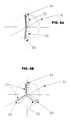
- the rotatable element 22 may be configured as a substantially circular rotatable disk 26, or as several arms in a plane uniformly spread around the axis of rotation 24, as shown in Figures 5a and 5b.
- a laser 28 is configured to emit a beam of incident radiation along an axis coincident with the axis of rotation 24.
- the beam of incident radiation 30 is redirected radially of the rotatable disk 26 by a beam redirecting element 32 located along the axis of rotation 24 of the rotatable element 22.
- the beam redirecting element 32 may include a mirror, a prism, or any optical instrument capable of changing the direction of an incident beam of radiation.
- the resultant beam 34 is directed orthogonally, or radially, of the disk 26 and passes through a lens 36. Thereafter, the resultant beam 34 is focused to produce a focus point 38 ( Figure 6) which is located a small distance away from the lens 36 when viewed in the radial direction.
- a web 40 is supported for movement in a direction indicated by arrow 42 along a path having a longitudinal axis 44.
- the web 40 may be paper, film, fabric, or other material.
- the web 40 is supported so as to form a concave trough 46.
- the path of the moving web 40 is configured such that rotation of the rotatable element 22 locates the focus point 38 on a line 48 (see Figure 7) non-parallel to the longitudinal axis 44 of the concave trough 46.
- the path as used herein generally refers to the space through which the web passes as it travels in the longitudinal direction indicated by arrow 42.
- the path may assume a concave shape which is equivalent to the concave trough 46.
- the line 48 is non-parallel to the longitudinal axis 44 of the concave trough 46 because the axis of rotation 24 of the rotatable element 22 extends at an angle ⁇ when viewed in plan view.
- the angle ⁇ of the rotatable element 22, may be large as shown in Figure 2A, or may be small, as shown in Figure 2C.
- the particular angle ⁇ of the rotatable element 22 is a factor in determining the precise configuration of the concave trough 46. As shown in Figure 2A, when the angle ⁇ is large, the concave trough 46 becomes deeper and more pronounced. However, as the amount of angle decreases, as shown in Figures 2B and 2C, the concave trough 46 becomes flatter and less pronounced.
- the movable web 40 is formed into the concave trough 46 by support means 50.
- the support means 50 may include upper and lower spaced-apart curved members 52 and 54, with the path of the moving web 40 being located therebetween.
- the upper curved member 52 and the lower curved member 54 form the movable web 40 into the concave trough 46.
- Either of the upper and lower curved members 52 and 54 may additionally include a roller 56, or a plurality of rollers, in order to assist movement of the movable web therealong.
- the support means 50 may include a stationary concave support surface 58, or a plurality of spaced apart stationary concave support surfaces 58, as shown in Figure 3B. Each of these surfaces may include rollers or an air cushion to assist the movement of the web 40 thereover.
- a void space 60 may be formed between adjacent ones of the spaced-apart support surfaces 58. The void space 60 would be located under an area over which the focus point 38 passes so that the focus point 38 does not contact the concave support surface 58.
- Exhaust means 62 may be utilized to remove dust and vapors which are produced during cutting or perforating operations performed on the moving web 40.
- the support means 50 may be configured to accommodate a single moveable web 40, or a plurality of moveable webs 40 placed side-by-side. Further, the support means 50 may be configured as a moving conveyor belt which supports the moveable web 40 thereon.
- Figures 4A through 4C show various configurations of the circular rotatable disk 26.
- the rotatable disk 26 may include a single lens 36.
- two or three lenses 36 may be used, as shown in Figures 4B and 4C, respectively, depending on the operation which is to be performed on the movable web 40.
- the rotatable element 22 may be configured as a hollow tubular arm member 70 rotatable about an axis of rotation 24, as shown in Figures 5A and 5B.
- Each hollow tubular arm member 70 includes a lens 36, and which configuration of tubular arm member used will depend on the operation which is to be performed on the movable web 40.
- the resulting beam 34 passes through an interior of a particular hollow tubular arm member 70.
- Figure 6 shows the rotatable element 22 configured as a rotatable disk'26.
- the rotatable disk 26 includes two lenses 36 spaced at diametrically opposed circumferential portions of the rotatable disk 26.
- the focus point 38 is spaced radially from the lens 36 by a small amount, and this small amount is taken into account when calculating the diameter of the rotatable disk 26, which is discussed below.
- Cross Direction Web Processor or Laser Cross Processor
- the variables related to the design of the Laser Cross Processor would include the following:
- T ⁇ *D*R
- Figures 8A through 8C are graphical representations of three trough configurations.
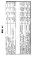
- Figure 8A shows a concave trough 46 which corresponds to the values set forth in Figure 9.
- Figure 8B shows a concave trough 46 corresponding to the values set forth in Figure 12.
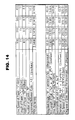
- Figure 8C shows a concave trough 46 which corresponds to the values set forth in Figure 14.
- D referring to the diameter of the disk actually refers to the diameter of the "focus point disk", which is shown in Figure 6.
- the values X and Y as shown in Figures 8A through 8C are coordinate points on a locus of points along an ellipse corresponding to the formula (X 2 /A 2 ) plus (Y 2 /B 2 ) equals 1, where "A” is equal to one-half of a major axis length of the ellipse and "B” is a equal to one-half of a minor axis length of the ellipse.
- a laser 28 directs an incident beam of radiation 30 onto the beam redirecting element 32 to be redirected to the lens 36.
- the resultant beam is focused onto the moving web and is moved on a line non-parallel to the longitudinal axis of the concave trough 46.
- the direction of rotation of the rotatable element 22 is at a precise angle to the direction of web travel such that the advance in web travel and the rotation of the rotatable element locate a line non-parallel to the longitudinal axis of the concave trough.
- the resulting line 49 on the web may ideally be directed perpendicularly to the longitudinal axis of the concave trough.
- the web processor may be configured to produce a score, a mark, a plurality of spaced-apart perforations, or a complete cut along this line.
- a score is the breaking of material fibers so that a line is formed along which the material may be conveniently folded.
- a laser scoring operation is performed by cutting the material to a predetermined partial depth. Perforating refers to the producing of holes in a pattern having a particular length, width and spacing. Perforating is performed by pulsing the laser to produce the desired perforation pattern.
- the rotational speed of the rotatable element 22 may vary during its rotation such that the rotational speed decreases as the focus point 38 at least initially travels along the path, and increases after reaching the major axis point at the center of the web 40. This change in rotational speed compensates for the relative speed between the rotatable element 22 and the moving web 40 so as to produce a more straight cut or perforation along the line.
- the beam redirecting means may be independently movable with respect to the rotatable element 22.
- the beam redirecting means 32 may be configured to oscillate as the rotatable element 22 performs a complete 360° revolution. It is only necessary that the beam redirecting element be aligned with the element 22 prior to the focus point 38 initially travelling along the path. This is especially the case where two or more lenses 36 are used so that a single beam redirecting element 32 may be utilized to direct the resultant beam 34 alternatively to each of the plurality of lenses 36.
- a single beam redirecting element may be used which splits the beam of incident radiation 30 into a plurality of resultant beams 34 which are directed to a corresponding number of lenses 36.
- this particular method is less desirable due to the increased power requirement placed on the laser 28. For example, if a beam redirecting element 32 were utilized which split the beam of incident radiation 30 into three resultant beams 34 which were directed to three separate lenses 36, the power requirements placed on the laser would approximately triple.
- the beam redirecting element 32 and the lens 36 may oscillate together through a circular arc which travels back and forth across the concave trough 46.
- the laser 28 may be energized as the beam redirecting element 32 and lens 36 travel in a first direction across the concave trough 36, and may be turned off as the beam redirecting element 32 and the lens 36 travel back to the initial position.
- the beam redirecting element 32 and the lens 36 may be stationary in order to perform a slitting operation along the axis of movement of the moveable web 40.
- An electrical controller or a mechanical shutter may be utilized to switch the beam of incident radiation 30 on and off to produce the desired effect on the movable web 40.
- Power supply modulation may also be utilized to produce the desired pulsing characteristics.
- Any suitable laser 28 may be utilized depending on the characteristics of the web material and the desired operation performed on the selected material.
- a carbon dioxide (CO 2 ) laser is preferred.
- a laser possesses several important advantages over mechanical cutting and perforating devices. For example, because there is no contact between the laser output and the material, such as paper, there is no tool wear normally associated with mechanical cutting blades. Because very high power and small spot size produce power densities sufficient to vaporize the material, the result is edge quality superior to fiber shearing or tearing actions. Further, dust is virtually eliminated. Finally, the fibers adjacent to the cut area may be fused by the laser, providing greater strength along the edge of the cut sheet.
- the laser may be used to perform operations on materials containing adhesives which would normally buildup on the mechanical blades over time.
- the web processor of the present invention can be utilized to cut various types of material including paper, abrasives, adhesive-backed materials, thin veneers made of wood, plastic, etc., or films. Further, the web processor may be utilized to cut multiple sheets stacked one atop the other and moving together, such as multipart carbonless paper.
- a method for treating a web 40 includes the steps of forming a movable web into a concave trough 46 having a longitudinal axis 44, rotating a rotatable element 22 about an axis of rotation 24, producing an incident beam of radiation 30 and directing the incident beam of radiation 30 to a beam redirecting element 32 to produce a resultant beam of radiation 34, directing the resultant beam of radiation 34 substantially orthogonally to the axis of rotation 24, focusing the resultant beam 34 with a lens 36 to produce a focus point 38 on the concave trough 46, and moving the web 40 in a direction 42 along the longitudinal axis 44 while rotating the rotatable element 22 to locate the focus point 38 on a line across the web 40, a path of travel of the focus point 38 being non-parallel to the longitudinal axis 44 of the concave trough 46.
- the method of treating a web 40 may further include the step of oscillating the beam redirecting element 32 and the lens 36 back and forth through a circular arc.
- the method may include the step of varying a rotational speed of the rotatable element 22 during rotation of the rotatable element 22 such that the rotational speed of the rotatable element 22 decreases as the focus point 38 at least initially travels along the path.
- the method of treating a web may include the step of using a plurality of lenses 36 to focus the resultant beam 34 to produce the focus point 38, with the plurality of lenses 38 being a part of the rotatable element 22 and being rotatable therewith.
- the beam redirecting element 32 is then oscillated as the plurality of lenses 36 continuously rotate in one direction to thereby direct the resultant beam 34 alternately to each of the plurality of lenses 36.
- the method of treating a web may be used to perform a plurality of different operations along the line on the movable web 40. For example, any one or more of a score, a mark, a plurality of spaced-apart perforations, or a complete cut may be produced by the cross-direction web processor.
- a web 40 which has been treated by the above method is also the subject of the present invention.
- the web 40 may have been processed to include any one or more of a score, a mark, a plurality of spaced-apart perforations, or a complete cut.
Landscapes
- Physics & Mathematics (AREA)
- Optics & Photonics (AREA)
- Engineering & Computer Science (AREA)
- Plasma & Fusion (AREA)
- Mechanical Engineering (AREA)
- Laser Beam Processing (AREA)
- Grinding And Polishing Of Tertiary Curved Surfaces And Surfaces With Complex Shapes (AREA)
Applications Claiming Priority (2)
| Application Number | Priority Date | Filing Date | Title |
|---|---|---|---|
| US08/867,119 US6038487A (en) | 1997-06-05 | 1997-06-05 | Cross direction web processor |
| US867119 | 1997-06-05 |
Publications (3)
| Publication Number | Publication Date |
|---|---|
| EP0882541A2 true EP0882541A2 (fr) | 1998-12-09 |
| EP0882541A3 EP0882541A3 (fr) | 2000-02-09 |
| EP0882541B1 EP0882541B1 (fr) | 2004-11-17 |
Family
ID=25349121
Family Applications (1)
| Application Number | Title | Priority Date | Filing Date |
|---|---|---|---|
| EP98302557A Expired - Lifetime EP0882541B1 (fr) | 1997-06-05 | 1998-04-01 | Processeur transversal de bande |
Country Status (5)
| Country | Link |
|---|---|
| US (1) | US6038487A (fr) |
| EP (1) | EP0882541B1 (fr) |
| CA (1) | CA2226825C (fr) |
| DE (1) | DE69827549T2 (fr) |
| ES (1) | ES2231943T3 (fr) |
Cited By (1)
| Publication number | Priority date | Publication date | Assignee | Title |
|---|---|---|---|---|
| WO2001000365A1 (fr) * | 1999-06-24 | 2001-01-04 | Sator Laser Gmbh | Dispositif pour couper des bandes de papier ou de matiere plastique |
Families Citing this family (9)
| Publication number | Priority date | Publication date | Assignee | Title |
|---|---|---|---|---|
| US7367931B2 (en) * | 2000-10-30 | 2008-05-06 | Pactiv Corporation | Laser cutoff stacker assembly |
| WO2002047980A2 (fr) * | 2000-10-30 | 2002-06-20 | Pactiv Corporation | Laser permettant de former des sachets a partir d'une feuille de materiel |
| US6423932B1 (en) * | 2001-02-16 | 2002-07-23 | William E. Lawson | Apparatus and method for high speed laser perforation of webs |
| US6945922B2 (en) * | 2001-11-30 | 2005-09-20 | Kimberly-Clark Worldwide, Inc. | System for cutting a moving web in the cross direction to form sheets of a given length at high web speeds |
| US20030124294A1 (en) * | 2001-12-28 | 2003-07-03 | Hodson Jay D. | Scored package and a method of making the same |
| US20030231811A1 (en) * | 2002-06-07 | 2003-12-18 | Hodson Jay D. | Internally scored film, package and methods of making the same |
| TW201009525A (en) * | 2008-08-18 | 2010-03-01 | Ind Tech Res Inst | Laser marking method and laser marking system |
| DE102010029139A1 (de) | 2010-05-19 | 2011-11-24 | Windmöller & Hölscher Kg | Vorrichtung und Verfahren zur Erzeugung von Schlauchabschnitten zur Herstellung von Beuteln |
| KR20170029411A (ko) * | 2014-04-18 | 2017-03-15 | 쥐디엠 에스.피.에이. | 재료의 웹을 절단하기 위한 장치 |
Family Cites Families (25)
| Publication number | Priority date | Publication date | Assignee | Title |
|---|---|---|---|---|
| GB968824A (en) * | 1962-09-25 | 1964-09-02 | Jagenberg Werke Ag | Method and apparatus for cutting paper and similar materials |
| US3226527A (en) * | 1963-10-23 | 1965-12-28 | William H Harding | Apparatus for perforating sheet material |
| US3909582A (en) * | 1971-07-19 | 1975-09-30 | American Can Co | Method of forming a line of weakness in a multilayer laminate |
| US3790744A (en) * | 1971-07-19 | 1974-02-05 | American Can Co | Method of forming a line of weakness in a multilayer laminate |
| DE2343996C2 (de) * | 1973-08-31 | 1982-09-16 | Winkler & Dünnebier, Maschinenfabrik und Eisengießerei GmbH & Co KG, 5450 Neuwied | Verfahren und Vorrichtung zum Herstellen von Briefumschlagzuschnitten |
| DE2754104C2 (de) * | 1977-12-05 | 1987-01-15 | Hauni-Werke Körber & Co KG, 2050 Hamburg | Vorrichtung zum Herstellen einer Zone gewünschter Luftdurchlässigkeit in einem Hüllmaterialstreifen für stabförmige Artikel der tabakverarbeitenden Industrie |
| US4410785A (en) * | 1978-06-07 | 1983-10-18 | Philip Morris Incorporated | Method and apparatus for perforation of sheet material by laser |
| CA1136305A (fr) * | 1978-07-26 | 1982-11-23 | William J. Becker | Substance adhesive pour former des documents en plusieurs exemplaires a partir de papier duplicateur sans carbone |
| US4297559A (en) * | 1979-05-10 | 1981-10-27 | Olin Corporation | Apparatus for controlled perforation of moving webs with fixed focus laser beam |
| GB2062576B (en) * | 1979-11-09 | 1983-01-12 | Lithprint Avon Ltd | Label and methods for making it |
| SE429769B (sv) * | 1980-04-01 | 1983-09-26 | Nordiskafilt Ab | Arkaggregat och sett att tillverka detsamma |
| DE3222394A1 (de) * | 1982-06-15 | 1983-12-15 | Richard Dipl.-Chem. 6000 Frankfurt Kraemer | Verfahren zur herstellung von formatgeschnittenen papierboegen mit glatten schnittraendern |
| US4535218A (en) * | 1982-10-20 | 1985-08-13 | Westinghouse Electric Corp. | Laser scribing apparatus and process for using |
| GB8307539D0 (en) * | 1983-03-18 | 1983-04-27 | Molins Plc | Cigarette manufacture |
| US4662708A (en) * | 1983-10-24 | 1987-05-05 | Armco Inc. | Optical scanning system for laser treatment of electrical steel and the like |
| CS258703B1 (en) * | 1985-01-17 | 1988-09-16 | Peter Urbanek | Method of decoration's selective formation on solid axially symmetrical products by means of laser and method for realization of this method |
| US4906605A (en) * | 1988-05-06 | 1990-03-06 | Minnesota Mining And Manufacturing Company | Carbonless paper printable in electrostatic copiers |
| NL9000224A (nl) * | 1990-01-30 | 1991-08-16 | Drent H H Maschf Bv | Werkwijze en inrichting voor het doorsnijden dan wel perforeren van een bewegende papierbaan. |
| IT1246830B (it) * | 1990-07-10 | 1994-11-28 | Gd Spa | Dispositivo per il taglio trasversale in spezzoni di un nastro mobile di moto continuo lungo un percorso determinato. |
| DE4023997B4 (de) * | 1990-07-28 | 2004-03-25 | Christian Majer Gmbh & Co. Kg. Maschinenfabrik | Schneidvorrichtung zur Ausführung geradliniger Schnitte in Papier und Pappe oder vergleichbaren messerschneidefähigen Materialien |
| EP0543926B1 (fr) * | 1990-08-17 | 1996-04-03 | Minnesota Mining And Manufacturing Company | Perforation au laser de papier |
| US5444035A (en) * | 1990-08-17 | 1995-08-22 | Minnesota Mining And Manufacturing Company | Laser perforation of paper |
| IT1253040B (it) * | 1991-09-25 | 1995-07-10 | Gd Spa | Dispositivo e metodo per la foratura di materiale di incarto di sigarette mediante almeno un fascio laser |
| FR2706797A1 (en) * | 1993-06-22 | 1994-12-30 | Alphatech Ind | Optical press-cutter for cutting sheets using a laser |
| US5611949A (en) * | 1994-05-04 | 1997-03-18 | Norfin International, Inc. | Method and apparatus for laser cutting separate items carried on a continuously moving web |
-
1997
- 1997-06-05 US US08/867,119 patent/US6038487A/en not_active Expired - Lifetime
-
1998
- 1998-01-13 CA CA002226825A patent/CA2226825C/fr not_active Expired - Fee Related
- 1998-04-01 DE DE69827549T patent/DE69827549T2/de not_active Expired - Fee Related
- 1998-04-01 ES ES98302557T patent/ES2231943T3/es not_active Expired - Lifetime
- 1998-04-01 EP EP98302557A patent/EP0882541B1/fr not_active Expired - Lifetime
Cited By (1)
| Publication number | Priority date | Publication date | Assignee | Title |
|---|---|---|---|---|
| WO2001000365A1 (fr) * | 1999-06-24 | 2001-01-04 | Sator Laser Gmbh | Dispositif pour couper des bandes de papier ou de matiere plastique |
Also Published As
| Publication number | Publication date |
|---|---|
| DE69827549T2 (de) | 2005-11-24 |
| CA2226825A1 (fr) | 1998-12-05 |
| CA2226825C (fr) | 2006-06-06 |
| ES2231943T3 (es) | 2005-05-16 |
| EP0882541A3 (fr) | 2000-02-09 |
| EP0882541B1 (fr) | 2004-11-17 |
| US6038487A (en) | 2000-03-14 |
| DE69827549D1 (de) | 2004-12-23 |
Similar Documents
| Publication | Publication Date | Title |
|---|---|---|
| US7988607B2 (en) | System and method for severing or perforating a web | |
| US5225649A (en) | Device for transversely cutting lengths of a strip traveling continuously along a predetermined route | |
| US6038487A (en) | Cross direction web processor | |
| FI90024C (fi) | Laserapparat foer repetitiv maerkning av ett roerligt arkmaterial | |
| US3981230A (en) | Apparatus for thermally machining thermoplastics sheet | |
| US4672168A (en) | Apparatus for perforating sheet material | |
| US7094193B2 (en) | High speed laser perforation of cigarette tipping paper | |
| JPS63188486A (ja) | 帯状シ−ト材料の穿孔方法及び装置 | |
| US5213649A (en) | Apparatus for receiving and cutting a continuous web | |
| JPH08225230A (ja) | 薄いウエブの切断装置並びに方法 | |
| JP2019155404A (ja) | レーザ加工機及びレーザ加工方法 | |
| CN1305632C (zh) | 卷筒纸打孔装置 | |
| EP0516199A1 (fr) | Méthode et dispositif pour le coupage ou la perforation d'une bande de papier en mouvement | |
| JP2003227062A (ja) | 不織布加工物品 | |
| US6924829B2 (en) | Web processing method and web processing device | |
| EP1305132B1 (fr) | Dispositif de decoupage et/ou de perforation | |
| WO2002067388A2 (fr) | Appareil et procede de perforation de toiles a grande vitesse par laser | |
| JPS63165091A (ja) | 穴の連続加工方法および装置 | |
| JP4312922B2 (ja) | レーザによるミシン目加工方法及び加工装置 | |
| WO2001051245A1 (fr) | Traitement d'une toile | |
| JPH01193195A (ja) | 連続印刷用紙用横切断目加工装置 | |
| JP4200735B2 (ja) | カッティングプロッタにおける刃先制御方法 | |
| FR2733447A1 (fr) | Procede et dispositifs de decoupe de materiau par faisceau laser | |
| JPH082510B2 (ja) | レーザ光溶接装置 | |
| JPH0592283A (ja) | レーザ加工方法及びその装置 |
Legal Events
| Date | Code | Title | Description |
|---|---|---|---|
| PUAI | Public reference made under article 153(3) epc to a published international application that has entered the european phase |
Free format text: ORIGINAL CODE: 0009012 |
|
| AK | Designated contracting states |
Kind code of ref document: A2 Designated state(s): BE DE ES FI FR GB IT |
|
| AX | Request for extension of the european patent |
Free format text: AL;LT;LV;MK;RO;SI |
|
| PUAL | Search report despatched |
Free format text: ORIGINAL CODE: 0009013 |
|
| AK | Designated contracting states |
Kind code of ref document: A3 Designated state(s): AT BE CH CY DE DK ES FI FR GB GR IE IT LI LU MC NL PT SE |
|
| AX | Request for extension of the european patent |
Free format text: AL;LT;LV;MK;RO;SI |
|
| 17P | Request for examination filed |
Effective date: 20000719 |
|
| AKX | Designation fees paid |
Free format text: BE DE ES FI FR GB IT |
|
| 17Q | First examination report despatched |
Effective date: 20020417 |
|
| GRAP | Despatch of communication of intention to grant a patent |
Free format text: ORIGINAL CODE: EPIDOSNIGR1 |
|
| GRAA | (expected) grant |
Free format text: ORIGINAL CODE: 0009210 |
|
| GRAS | Grant fee paid |
Free format text: ORIGINAL CODE: EPIDOSNIGR3 |
|
| AK | Designated contracting states |
Kind code of ref document: B1 Designated state(s): BE DE ES FI FR GB IT |
|
| REG | Reference to a national code |
Ref country code: GB Ref legal event code: FG4D |
|
| RIN1 | Information on inventor provided before grant (corrected) |
Inventor name: WELLS, JEFFREY L. Inventor name: PINGEL, CHARLES J. Inventor name: BALSTER, LESTER A. |
|
| REF | Corresponds to: |
Ref document number: 69827549 Country of ref document: DE Date of ref document: 20041223 Kind code of ref document: P |
|
| REG | Reference to a national code |
Ref country code: ES Ref legal event code: FG2A Ref document number: 2231943 Country of ref document: ES Kind code of ref document: T3 |
|
| ET | Fr: translation filed | ||
| PLBE | No opposition filed within time limit |
Free format text: ORIGINAL CODE: 0009261 |
|
| STAA | Information on the status of an ep patent application or granted ep patent |
Free format text: STATUS: NO OPPOSITION FILED WITHIN TIME LIMIT |
|
| 26N | No opposition filed |
Effective date: 20050818 |
|
| PGFP | Annual fee paid to national office [announced via postgrant information from national office to epo] |
Ref country code: FI Payment date: 20080314 Year of fee payment: 11 |
|
| PGFP | Annual fee paid to national office [announced via postgrant information from national office to epo] |
Ref country code: FR Payment date: 20080313 Year of fee payment: 11 Ref country code: ES Payment date: 20080418 Year of fee payment: 11 Ref country code: DE Payment date: 20080320 Year of fee payment: 11 |
|
| PGFP | Annual fee paid to national office [announced via postgrant information from national office to epo] |
Ref country code: BE Payment date: 20080416 Year of fee payment: 11 Ref country code: IT Payment date: 20080331 Year of fee payment: 11 |
|
| BERE | Be: lapsed |
Owner name: *APPLETON PAPERS INC. Effective date: 20090430 |
|
| PGFP | Annual fee paid to national office [announced via postgrant information from national office to epo] |
Ref country code: GB Payment date: 20090421 Year of fee payment: 12 |
|
| REG | Reference to a national code |
Ref country code: FR Ref legal event code: ST Effective date: 20091231 |
|
| PG25 | Lapsed in a contracting state [announced via postgrant information from national office to epo] |
Ref country code: FI Free format text: LAPSE BECAUSE OF NON-PAYMENT OF DUE FEES Effective date: 20090401 Ref country code: DE Free format text: LAPSE BECAUSE OF NON-PAYMENT OF DUE FEES Effective date: 20091103 |
|
| PG25 | Lapsed in a contracting state [announced via postgrant information from national office to epo] |
Ref country code: FR Free format text: LAPSE BECAUSE OF NON-PAYMENT OF DUE FEES Effective date: 20091222 |
|
| PG25 | Lapsed in a contracting state [announced via postgrant information from national office to epo] |
Ref country code: BE Free format text: LAPSE BECAUSE OF NON-PAYMENT OF DUE FEES Effective date: 20090430 |
|
| REG | Reference to a national code |
Ref country code: ES Ref legal event code: FD2A Effective date: 20090402 |
|
| PG25 | Lapsed in a contracting state [announced via postgrant information from national office to epo] |
Ref country code: ES Free format text: LAPSE BECAUSE OF NON-PAYMENT OF DUE FEES Effective date: 20090402 |
|
| GBPC | Gb: european patent ceased through non-payment of renewal fee |
Effective date: 20100401 |
|
| PG25 | Lapsed in a contracting state [announced via postgrant information from national office to epo] |
Ref country code: IT Free format text: LAPSE BECAUSE OF NON-PAYMENT OF DUE FEES Effective date: 20090401 Ref country code: GB Free format text: LAPSE BECAUSE OF NON-PAYMENT OF DUE FEES Effective date: 20100401 |