EP0882683A2 - Verstärkungslichtwellenleiter und Verfahren zu seiner Herstellung - Google Patents
Verstärkungslichtwellenleiter und Verfahren zu seiner Herstellung Download PDFInfo
- Publication number
- EP0882683A2 EP0882683A2 EP98110355A EP98110355A EP0882683A2 EP 0882683 A2 EP0882683 A2 EP 0882683A2 EP 98110355 A EP98110355 A EP 98110355A EP 98110355 A EP98110355 A EP 98110355A EP 0882683 A2 EP0882683 A2 EP 0882683A2
- Authority
- EP
- European Patent Office
- Prior art keywords
- core
- optical waveguide
- reinforcing
- amplifying
- waveguide according
- Prior art date
- Legal status (The legal status is an assumption and is not a legal conclusion. Google has not performed a legal analysis and makes no representation as to the accuracy of the status listed.)
- Withdrawn
Links
Images


Classifications
-
- H—ELECTRICITY
- H01—ELECTRIC ELEMENTS
- H01S—DEVICES USING THE PROCESS OF LIGHT AMPLIFICATION BY STIMULATED EMISSION OF RADIATION [LASER] TO AMPLIFY OR GENERATE LIGHT; DEVICES USING STIMULATED EMISSION OF ELECTROMAGNETIC RADIATION IN WAVE RANGES OTHER THAN OPTICAL
- H01S3/00—Lasers, i.e. devices using stimulated emission of electromagnetic radiation in the infrared, visible or ultraviolet wave range
- H01S3/05—Construction or shape of optical resonators; Accommodation of active medium therein; Shape of active medium
- H01S3/06—Construction or shape of active medium
- H01S3/063—Waveguide lasers, i.e. whereby the dimensions of the waveguide are of the order of the light wavelength
- H01S3/067—Fibre lasers
- H01S3/06708—Constructional details of the fibre, e.g. compositions, cross-section, shape or tapering
-
- C—CHEMISTRY; METALLURGY
- C03—GLASS; MINERAL OR SLAG WOOL
- C03B—MANUFACTURE, SHAPING, OR SUPPLEMENTARY PROCESSES
- C03B19/00—Other methods of shaping glass
- C03B19/01—Other methods of shaping glass by progressive fusion or sintering of powdered glass onto a shaping substrate, i.e. accretion, e.g. plasma oxidation deposition
-
- C—CHEMISTRY; METALLURGY
- C03—GLASS; MINERAL OR SLAG WOOL
- C03B—MANUFACTURE, SHAPING, OR SUPPLEMENTARY PROCESSES
- C03B19/00—Other methods of shaping glass
- C03B19/14—Other methods of shaping glass by gas- or vapour- phase reaction processes
- C03B19/1415—Reactant delivery systems
-
- C—CHEMISTRY; METALLURGY
- C03—GLASS; MINERAL OR SLAG WOOL
- C03B—MANUFACTURE, SHAPING, OR SUPPLEMENTARY PROCESSES
- C03B37/00—Manufacture or treatment of flakes, fibres, or filaments from softened glass, minerals, or slags
- C03B37/01—Manufacture of glass fibres or filaments
- C03B37/012—Manufacture of preforms for drawing fibres or filaments
- C03B37/014—Manufacture of preforms for drawing fibres or filaments made entirely or partially by chemical means, e.g. vapour phase deposition of bulk porous glass either by outside vapour deposition [OVD], or by outside vapour phase oxidation [OVPO] or by vapour axial deposition [VAD]
- C03B37/018—Manufacture of preforms for drawing fibres or filaments made entirely or partially by chemical means, e.g. vapour phase deposition of bulk porous glass either by outside vapour deposition [OVD], or by outside vapour phase oxidation [OVPO] or by vapour axial deposition [VAD] by glass deposition on a glass substrate, e.g. by inside-, modified-, plasma- or plasma modified- chemical vapour deposition [ICVD, MCVD, PCVD, PMCVD], i.e. by thin layer coating on the inside or outside of a glass tube or on a glass rod
- C03B37/01807—Reactant delivery systems, e.g. reactant deposition burners
-
- C—CHEMISTRY; METALLURGY
- C03—GLASS; MINERAL OR SLAG WOOL
- C03C—CHEMICAL COMPOSITION OF GLASSES, GLAZES OR VITREOUS ENAMELS; SURFACE TREATMENT OF GLASS; SURFACE TREATMENT OF FIBRES OR FILAMENTS MADE FROM GLASS, MINERALS OR SLAGS; JOINING GLASS TO GLASS OR OTHER MATERIALS
- C03C13/00—Fibre or filament compositions
- C03C13/04—Fibre optics, e.g. core and clad fibre compositions
- C03C13/045—Silica-containing oxide glass compositions
-
- C—CHEMISTRY; METALLURGY
- C03—GLASS; MINERAL OR SLAG WOOL
- C03C—CHEMICAL COMPOSITION OF GLASSES, GLAZES OR VITREOUS ENAMELS; SURFACE TREATMENT OF GLASS; SURFACE TREATMENT OF FIBRES OR FILAMENTS MADE FROM GLASS, MINERALS OR SLAGS; JOINING GLASS TO GLASS OR OTHER MATERIALS
- C03C17/00—Surface treatment of glass, not in the form of fibres or filaments, by coating
- C03C17/02—Surface treatment of glass, not in the form of fibres or filaments, by coating with glass
-
- C—CHEMISTRY; METALLURGY
- C03—GLASS; MINERAL OR SLAG WOOL
- C03B—MANUFACTURE, SHAPING, OR SUPPLEMENTARY PROCESSES
- C03B2201/00—Type of glass produced
- C03B2201/06—Doped silica-based glasses
- C03B2201/30—Doped silica-based glasses doped with metals, e.g. Ga, Sn, Sb, Pb or Bi
- C03B2201/31—Doped silica-based glasses doped with metals, e.g. Ga, Sn, Sb, Pb or Bi doped with germanium
-
- C—CHEMISTRY; METALLURGY
- C03—GLASS; MINERAL OR SLAG WOOL
- C03B—MANUFACTURE, SHAPING, OR SUPPLEMENTARY PROCESSES
- C03B2201/00—Type of glass produced
- C03B2201/06—Doped silica-based glasses
- C03B2201/30—Doped silica-based glasses doped with metals, e.g. Ga, Sn, Sb, Pb or Bi
- C03B2201/34—Doped silica-based glasses doped with metals, e.g. Ga, Sn, Sb, Pb or Bi doped with rare earth metals, i.e. with Sc, Y or lanthanides, e.g. for laser-amplifiers
-
- C—CHEMISTRY; METALLURGY
- C03—GLASS; MINERAL OR SLAG WOOL
- C03B—MANUFACTURE, SHAPING, OR SUPPLEMENTARY PROCESSES
- C03B2201/00—Type of glass produced
- C03B2201/06—Doped silica-based glasses
- C03B2201/30—Doped silica-based glasses doped with metals, e.g. Ga, Sn, Sb, Pb or Bi
- C03B2201/34—Doped silica-based glasses doped with metals, e.g. Ga, Sn, Sb, Pb or Bi doped with rare earth metals, i.e. with Sc, Y or lanthanides, e.g. for laser-amplifiers
- C03B2201/36—Doped silica-based glasses doped with metals, e.g. Ga, Sn, Sb, Pb or Bi doped with rare earth metals, i.e. with Sc, Y or lanthanides, e.g. for laser-amplifiers doped with rare earth metals and aluminium, e.g. Er-Al co-doped
-
- H—ELECTRICITY
- H01—ELECTRIC ELEMENTS
- H01S—DEVICES USING THE PROCESS OF LIGHT AMPLIFICATION BY STIMULATED EMISSION OF RADIATION [LASER] TO AMPLIFY OR GENERATE LIGHT; DEVICES USING STIMULATED EMISSION OF ELECTROMAGNETIC RADIATION IN WAVE RANGES OTHER THAN OPTICAL
- H01S3/00—Lasers, i.e. devices using stimulated emission of electromagnetic radiation in the infrared, visible or ultraviolet wave range
- H01S3/05—Construction or shape of optical resonators; Accommodation of active medium therein; Shape of active medium
- H01S3/06—Construction or shape of active medium
- H01S3/063—Waveguide lasers, i.e. whereby the dimensions of the waveguide are of the order of the light wavelength
-
- H—ELECTRICITY
- H01—ELECTRIC ELEMENTS
- H01S—DEVICES USING THE PROCESS OF LIGHT AMPLIFICATION BY STIMULATED EMISSION OF RADIATION [LASER] TO AMPLIFY OR GENERATE LIGHT; DEVICES USING STIMULATED EMISSION OF ELECTROMAGNETIC RADIATION IN WAVE RANGES OTHER THAN OPTICAL
- H01S3/00—Lasers, i.e. devices using stimulated emission of electromagnetic radiation in the infrared, visible or ultraviolet wave range
- H01S3/14—Lasers, i.e. devices using stimulated emission of electromagnetic radiation in the infrared, visible or ultraviolet wave range characterised by the material used as the active medium
- H01S3/16—Solid materials
- H01S3/1601—Solid materials characterised by an active (lasing) ion
- H01S3/1603—Solid materials characterised by an active (lasing) ion rare earth
Definitions
- the invention relates to an amplifying optical waveguide consisting of an optical fiber core and an optical waveguide sheath, in which the Volume of the fiber optic core predominantly made of one material good transmission properties, in which as Reinforcing material complexes from a separator substance coated rare earth ions are arranged statistically distributed.
- Such an amplifying optical waveguide or a method for its Production is known (DE - A - 42 09 004).
- Reinforcing light waveguides are primarily those at which an amplification of light in the wavelength range at 1550 nm takes place.
- Such amplifying light waveguides have an inexpensive Relationship between pump power and gain. If the core of the Reinforcing light waveguide, for example erbium, can be doped with a pump power of 30 mW a gain of 40 dB can be achieved.
- the Reinforcement material made of amorphous agglomerates of a variety of Complexes.
- the measure succeeds in making the largest possible Number of rare earth ions in the core of the amplifying optical fiber to be installed so that they are optimal for a given pump power stimulated emission and a coherent amplification of Light is achieved.
- the complex shown in Fig. 1 consists of the rare earth ion 1 in the center, which is surrounded by a separator substance. This has the function of optically isolating the rare earth ion from one another. For example, if the complex is built into an amplifying optical fiber core, then the rare earth ion is an erbium ion.
- the separator substance is made, for example, of aluminum fluoride (AlF 3 ), so that the rare earth ion 1 is surrounded by aluminum ions 2 and fluorine ions 3.
- agglomerates 4 or clumps are now formed, which are arranged unevenly, that is to say statistically distributed, in the material of the amplifying optical waveguide core 5, as can be seen from FIG. 2.
- Such an agglomerate has a diameter of a few hundred nanometers or more, for example.
- the material of the core 5 can be, for example, a material commonly used for optical waveguides, such as silicon dioxide (SiO 2 ), the refractive index of which has been adapted by doping with another material, for example germanium dioxide (GeO 2 ). In principle, however, other materials can also be used as the core material.
- the Reinforcing effect of the amplifying fiber optic core passing light can be illustrated when the rare earth ions of Complexes in agglomerate 4 are excited by a pump laser.
- This in the light 6 entering the agglomerate 4 is in the agglomerate 4 reflected several times and can therefore penetrate several Complexes are reinforced several times.
- the amplified light 7 can in the pumped amplifying optical fiber core 5 several in succession Run through agglomerates 4 and be reinforced again there. Thereby there is an overall higher gain than in the known Amplifying fiber optic cables.
- the Wavelength width of the amplified light an optimal size.
- Fig. 4 shows the side view of an amplifying optical fiber, which has a core 5 with agglomerates 4 according to FIG. 2.
- the core 5 is from the optical waveguide sleeve 8, which - as with optical fibers usual - from a material with a lower refractive index than that Refractive index of core 5 exists.
- Optical waveguide 4 can be one act threadlike or a planar optical waveguide.
- a thread-shaped optical waveguide surrounds the optical waveguide sheath 8 Core 5 concentric.
- Optical waveguide sleeve 8 made of planar layers on both sides of the for example strip-shaped core 5.
- Fig. 5 shows the embodiment of a device with a Optical fiber core can be manufactured with agglomerates. It contains a known oxyhydrogen gas burner with which layers of glass or porous glass layers produced by the flame hydrolysis process can be.
- Such devices are known from DE-A-28 35 326.
- she consist of several tubes arranged concentrically to each other, the burner with the tube 9 arranged in the center Material is supplied from which the glass layer to be produced is produced becomes.
- the tube 10 is usually oxygen and the tube 11th Hydrogen supplied.
- the tube 12 carries an inert gas, for example Argon, which has several functions, for example the current of the Shield and cool burner gases from the outside.
- the tube 9 of the two Pipes 13 and 14 fed.
- Feed materials of the core glass are supplied in gaseous form, for example silicon tetrachloride and germanium tetrachloride together with argon.
- the tube 14 the starting materials for the generation the agglomerates fed.
- the materials from which the complexes arise i.e. H. the rare earth material and the separator material together in gaseous form with a gas such as argon.
- the complexes or the Agglomerates can also be used as a fine powder in a gas stream, which also consists of argon, are introduced into the burner.
- the device shown in FIG. 6 differs from the device in FIG Fig. 5 in that the tubes 13 and 14 arranged coaxially to each other the oxyhydrogen burner are guided.
- the components of the device which are identical to the components of the device according to FIG. 5 the same reference numerals.
- a device which is suitable for making a fine powder (d ⁇ 0.2 ⁇ m) to generate a fluid, which in a Gas flow can be fed to the oxyhydrogen burner.
- the device contains a container 15 in the above a gas permeable bottom 16 the powdery material is arranged.
- the bottom of the container 15 is provided with a pipe connection 17 through which a gas is supplied becomes. This gas penetrates the powder layer 18 in the container 16 and becomes discharged through the gas outlets 19.
- a tube is immersed in the powder layer 18 20, which opens into the tube 21, which carries the gas stream in the the powder-gas mixture is to be fed to the oxyhydrogen burner.
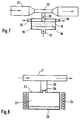
- Fig. 8 shows a device with which the starting materials of Agglomerates can be generated in gaseous form during manufacture of the fiber optic core is glazed together with its raw materials to become.
- This device consists of a pressure-resistant container 23, which is provided with a heater 24. At the top of the container 23 is a very small opening 25 which opens into a tube 20. The Pipe 20 in turn opens into the tube 21. Pipes 20 and 21 correspond those of the device according to FIG. 7. On the bottom of the container 23 are the starting materials for the generation of the complexes or Agglomerates.
- the device in FIG. 8 is a So-called Knudsen cell, as also in DE-A-42 09 004 is described.
- the gaseous materials for the complexes or the agglomerates are generated in the following way: With the substances in the container 23 for example, erbium chloride and aluminum chloride. If the container 23, for example, to a temperature of about 800 ° C. is heated, then arises because of the volatile aluminum high pressure. Through the very small opening 25, which has a diameter about 100 to 200 microns, that can over the solid mixture 26th lying gas 27 of the composition erbium chloride / aluminum chloride escape through the opening. Depending on the size of the opening 25 arise thereby agglomerates of a hundred or more individual molecules. The Agglomerates are entrained by the gas flow in the pipe for Glazing point of the core glass material transported and there in the Core glass installed.
Landscapes
- Chemical & Material Sciences (AREA)
- Engineering & Computer Science (AREA)
- Materials Engineering (AREA)
- Organic Chemistry (AREA)
- Physics & Mathematics (AREA)
- Chemical Kinetics & Catalysis (AREA)
- General Chemical & Material Sciences (AREA)
- Geochemistry & Mineralogy (AREA)
- Life Sciences & Earth Sciences (AREA)
- Manufacturing & Machinery (AREA)
- Optics & Photonics (AREA)
- Electromagnetism (AREA)
- Plasma & Fusion (AREA)
- General Life Sciences & Earth Sciences (AREA)
- Lasers (AREA)
- Glass Compositions (AREA)
- Optical Fibers, Optical Fiber Cores, And Optical Fiber Bundles (AREA)
- Manufacture, Treatment Of Glass Fibers (AREA)
Abstract
Description
- Fig. 1
- eine zweidimensionale Darstellung des Komplexes,
- Fig. 2
- eine schematische Darstellung eines Ausschnittes aus einem Verstärkungslichtwellenleiters mit Agglomeraten,
- Fig. 3
- eine schematische Darstellung eines Agglomerates,
- Fig. 4
- den Ausschnitt aus einem Verstärkungslichtwellenleiter mit einem Kern gemäß Fig. 2,
- Fig. 5
- schematisch eine Vorrichtung zur Herstellung eines Agglomerate enthaltenden Verstärkungslichtwellenleiterkerns,
- Fig. 6
- schematisch eine andere zur Herstellung eines Agglomerate enthaltenden Verstärkungslichtwellenleiterkerns,
- Fig. 7
- schematisch eine Vorrichtung zur Herstellung eines Pulver-Gasgemisches und
- Fig. 8
- schematisch eine Vorrichtung zur Herstellung eines Gasgemisches, welches Seltenerd-Ionen enthält.
Claims (9)
- Verstärkungslichtwellenleiter bestehend aus einem Lichtwellenleiterkern und einer Lichtwellenleiterhülle, bei dem das Volumen des Lichtwellenleiterkerns überwiegend aus einem Werkstoff mit guten Transmissionseigenschaften besteht, in welchem als Verstärkungswerkstoff Komplexe aus von einer Separatorsubstanz umhüllten Seltenerd-Ionen statistisch verteilt angeordnet sind,
dadurch gekennzeichnet,
daß der Verstärkungswerkstoff aus amorphen Agglomeraten einer Vielzahl von Komplexen besteht. - Verstärkungslichtwellenleiter nach Anspruch 1, dadurch gekennzeichnet, daß das Agglomerat aus mehr als tausend Einzelmolekülen besteht und einen Durchmesser zwischen 10-9 und 10-6 m aufweist.
- Verstärkungslichtwellenleiter nach den Ansprüchen 1 und 2, dadurch gekennzeichnet, daß die Seltenerd-Ionen aus Elementen entsprechend des zu verstärkenden Wellenlängenbereiches, wie Erbium oder Neodym bzw. Praseodym bestehen.
- Verstärkungslichtwellenleiter nach den Ansprüchen 1 bis 3, dadurch gekennzeichnet, daß die Separatorsubstanz aus einer Aluminiumverbindung besteht.
- Verstärkungslichtwellenleiter nach den Ansprüchen 1 bis 3, dadurch gekennzeichnet, daß die Separatorsuchstanz aus einer Lanthanverbindung besteht.
- Verstärkungslichtwellenleiter nach den Ansprüchen 1 bis 3, dadurch gekennzeichnet, daß die Differenz zwischen den Brechungsindizes des Transmissionswerkstoffes und des Verstärkungswerkstoffes ca. 40 x 10-3 beträgt.
- Verfahren zur Herstellung des Kerns eines planaren Verstärkungslichtwellenleiters nach wenigstens einem der Ansprüche 1 bis 6, dadurch gekennzeichnet, daß ein Gemisch aus Pulvern des Kernwerkstoffes und des Verstärkerwerkstoffes mittels eines Trägergasstromes in einem Knallgasbrenner eingeleitet und von diesem auf einem Substrat abgeschieden wird, die derart abgeschiedene Schicht erforderlichenfalls nachgesintert und aus ihr die Lichtwellenleiterkernschicht strukturiert wird.
- Verfahren zur Herstellung des Kerns eines planaren Verstärkungslichtwellenleiters nach wenigstens einem der Ansprüche 1 bis 6, dadurch gekennzeichnet, daß die gasförmigen Ausgangswerkstoffe des Kernwerkstoffs zusammen mit dem pulverförmigen Verstärkerwerkstoff in einen Knallgasbrenner eingeleitet und von diesem als poröse Schicht auf einem Substrat abgeschieden werden, die derart abgeschiedene Schicht zu Glas gesintert und aus ihr die Lichtwellenleiterkernschicht strukturiert wird.
- Verfahren zur Herstellung des Kerns eines faserförmigen Verstärkungslichtwellenleiters nach wenigstens einem der Ansprüche 1 bis 6, dadurch gekennzeichnet, daß die Ionen des Seltenerdwerkstoffes gemeinsam mit der Seporatorsubstanz und dem Kernausgangswerkstoff gasförmig in ein Quarzglasrohr eingeleitet und dort als glasige Schicht durch reaktive Abscheidung aus der Gasphase auf der Innenwand niedergeschlagen werden.
Applications Claiming Priority (2)
| Application Number | Priority Date | Filing Date | Title |
|---|---|---|---|
| DE19723833A DE19723833A1 (de) | 1997-06-06 | 1997-06-06 | Verstärkungslichtwellenleiter und Verfahren zu seiner Herstellung |
| DE19723833 | 1997-06-06 |
Publications (2)
| Publication Number | Publication Date |
|---|---|
| EP0882683A2 true EP0882683A2 (de) | 1998-12-09 |
| EP0882683A3 EP0882683A3 (de) | 1999-04-07 |
Family
ID=7831646
Family Applications (1)
| Application Number | Title | Priority Date | Filing Date |
|---|---|---|---|
| EP98110355A Withdrawn EP0882683A3 (de) | 1997-06-06 | 1998-06-05 | Verstärkungslichtwellenleiter und Verfahren zu seiner Herstellung |
Country Status (4)
| Country | Link |
|---|---|
| US (1) | US6285494B1 (de) |
| EP (1) | EP0882683A3 (de) |
| JP (1) | JPH1187830A (de) |
| DE (1) | DE19723833A1 (de) |
Families Citing this family (1)
| Publication number | Priority date | Publication date | Assignee | Title |
|---|---|---|---|---|
| FR2890958B1 (fr) * | 2005-09-16 | 2010-09-17 | Cit Alcatel | Preforme destinee a la fabrication d'une fibre optique comprenant des nanoparticules et procede de fabrication d'une fibre optique mettant en oeuvre une telle preforme |
Family Cites Families (20)
| Publication number | Priority date | Publication date | Assignee | Title |
|---|---|---|---|---|
| FR1353708A (fr) * | 1962-03-06 | 1964-02-28 | Mosaic Fabrications | Faisceaux de fibres et leur procédé de fabrication |
| JPS5927728B2 (ja) * | 1977-08-11 | 1984-07-07 | 日本電信電話株式会社 | 煤状ガラスロッドの製造方法 |
| DE3324539A1 (de) * | 1983-07-07 | 1985-01-17 | Siemens AG, 1000 Berlin und 8000 München | Verfahren zur herstellung von glas durch abscheidung aus der gasphase |
| JPS60239330A (ja) * | 1984-05-10 | 1985-11-28 | Agency Of Ind Science & Technol | ガラス・ブロツクの製造方法 |
| US4826288A (en) | 1987-04-09 | 1989-05-02 | Polaroid Corporation, Patent Department | Method for fabricating optical fibers having cores with high rare earth content |
| DE4028821A1 (de) * | 1990-09-11 | 1992-03-12 | Siemens Ag | Optische faser aus einem mit kationen eines elements aus den seltenen erden dotierten glas |
| JPH0782999B2 (ja) * | 1991-04-15 | 1995-09-06 | 株式会社半導体プロセス研究所 | 気相成長膜の形成方法、半導体製造装置、および半 導体装置 |
| FR2676435B1 (fr) * | 1991-05-14 | 1995-03-10 | France Telecom | Milieu en verre d'halogenures contenant des ions d'uranium trivalents et procede de fabrication de ce milieu. |
| AU653411B2 (en) * | 1991-07-19 | 1994-09-29 | Sumitomo Electric Industries, Ltd. | Method for producing glass preform for optical fiber |
| US5581398A (en) * | 1991-12-23 | 1996-12-03 | Akzo Nobel Nv | Polymeric optical amplifier doped with lanthanide |
| WO1993017449A1 (en) * | 1992-02-25 | 1993-09-02 | Energy Conversion Devices, Inc. | Semiconductor with ordered clusters and laser ablation method for the fabrication thereof |
| DE4209004C2 (de) * | 1992-03-20 | 2001-06-21 | Sel Alcatel Ag | Verfahren und Vorrichtung zur Herstellung einer Lichtwellenleiter-Vorform |
| JPH06183751A (ja) * | 1992-12-21 | 1994-07-05 | Nippon Telegr & Teleph Corp <Ntt> | 光導波膜の製造方法 |
| DE4306933A1 (de) * | 1993-03-05 | 1994-09-08 | Sel Alcatel Ag | Verfahren zur Herstellung einer Verstärkungs-Lichtwellenleiter-Vorform |
| BE1007071A3 (nl) * | 1993-04-28 | 1995-03-07 | Philips Electronics Nv | Optische versterker. |
| FR2707285B1 (fr) * | 1993-07-06 | 1995-08-11 | Alcatel Fibres Optiques | Préforme pour fibre optique, procédé de fabrication d'une telle préforme et fibre optique obtenue à partir de cette préforme. |
| FR2714046B1 (fr) * | 1993-12-16 | 1996-03-08 | France Telecom | Matériaux vitrocéramiques notamment pour lasers et amplificateurs optiques dopés en terres rares et procédé de fabrication de tels matériaux. |
| IT1267418B1 (it) * | 1994-03-16 | 1997-02-05 | Cselt Centro Studi Lab Telecom | Procedimento per la realizzazione di fibre ottiche monomodo in vetro fluorurato. |
| DE4420287A1 (de) * | 1994-06-10 | 1995-12-14 | Sel Alcatel Ag | Lichtwellenleiter für faseroptische Verstärker für den Wellenlängenbereich um 1550 nm |
| KR100342189B1 (ko) | 1995-07-12 | 2002-11-30 | 삼성전자 주식회사 | 휘발성복합체를사용한희토류원소첨가광섬유제조방법 |
-
1997
- 1997-06-06 DE DE19723833A patent/DE19723833A1/de not_active Withdrawn
-
1998
- 1998-06-04 JP JP10155791A patent/JPH1187830A/ja active Pending
- 1998-06-05 EP EP98110355A patent/EP0882683A3/de not_active Withdrawn
- 1998-06-05 US US09/092,410 patent/US6285494B1/en not_active Expired - Fee Related
Also Published As
| Publication number | Publication date |
|---|---|
| JPH1187830A (ja) | 1999-03-30 |
| EP0882683A3 (de) | 1999-04-07 |
| US6285494B1 (en) | 2001-09-04 |
| DE19723833A1 (de) | 1998-12-10 |
Similar Documents
| Publication | Publication Date | Title |
|---|---|---|
| DE69833283T2 (de) | Tellurit-Glas, optischer Verstärker und Lichtquelle | |
| DE69122955T2 (de) | Faseroptischer Verstärker und Koppler | |
| DE69120402T2 (de) | Faseroptischer Verstärker mit Filter | |
| DE3856092T2 (de) | Optische Faser mit fluoreszentem Additiv | |
| DE19756868B4 (de) | Hohlwellenleiter und Verfahren zu seiner Herstellung | |
| DE2930398C2 (de) | ||
| DE60025823T2 (de) | Optische wellenleiterfaser mit niedrigem wasserpeak und verfahren zu ihrer herstellung | |
| DE69920251T2 (de) | Lichtverstärkendes glas, lichtverstärkendes mediumund harzbeschichtetes lichtverstärkendes medium | |
| DE68906032T2 (de) | Verstaerkung optischer signale. | |
| WO1997012429A1 (de) | Doppelkern-lichtleitfaser, verfahren zu ihrer herstellung, doppelkern-faserlaser und doppelkern-faserverstärker | |
| DE2930399A1 (de) | Optische gradientenindex-faser grosser bandbreite und verfahren zu ihrer herstellung | |
| DE2723972A1 (de) | Optische uebertragungsanlage und kopplungselement fuer die optische uebertragungsanlage sowie eine linse, die fuer das kopplungselement geeignet ist | |
| DE3221836C2 (de) | Einzelmodenfaser | |
| DE2821642A1 (de) | Faser-lichtwellenleiter und verfahren zu dessen herstellung | |
| DE2835326A1 (de) | Verfahren und vorrichtung zur herstellung eines glas-rohlings fuer optische fasern | |
| DE69031571T2 (de) | Verfahren zum Herstellen einer optischen Faservorform | |
| DE2418168A1 (de) | Optische uebertragungsleitung aus glas | |
| DE102010011224B4 (de) | Lichtwellenleiter-Verstärker und Verfahren zu dessen Herstellung | |
| DE69410352T2 (de) | Verfahren zum Herstellen eines zylindrischen Körpers aus Multikomponentenglas in Form eines Rohres und/oder eines Stabes | |
| DE2313202C2 (de) | Optischer Wellenleiter | |
| DE69608455T2 (de) | Optischer wellenleiter,wellenleiterverstärker und -laser | |
| DE69206640T2 (de) | Optisch aktives Glas und dieses nutzende Vorrichtung | |
| DE69311168T2 (de) | Optische Faser zum Anschluss an einen Wellenleiter und Verfahren zu ihrer Herstellung | |
| DE69104738T2 (de) | Doppelkern-Aktivfaser als optischer Breitband-Signal-Verstärker. | |
| DE69113403T2 (de) | Optischer Koppler und Verfahren zu seiner Herstellung. |
Legal Events
| Date | Code | Title | Description |
|---|---|---|---|
| PUAI | Public reference made under article 153(3) epc to a published international application that has entered the european phase |
Free format text: ORIGINAL CODE: 0009012 |
|
| AK | Designated contracting states |
Kind code of ref document: A2 Designated state(s): DE ES FR GB IT NL SE |
|
| AX | Request for extension of the european patent |
Free format text: AL;LT;LV;MK;RO;SI |
|
| PUAL | Search report despatched |
Free format text: ORIGINAL CODE: 0009013 |
|
| RAP3 | Party data changed (applicant data changed or rights of an application transferred) |
Owner name: ALCATEL |
|
| AK | Designated contracting states |
Kind code of ref document: A3 Designated state(s): AT BE CH CY DE DK ES FI FR GB GR IE IT LI LU MC NL PT SE |
|
| AX | Request for extension of the european patent |
Free format text: AL;LT;LV;MK;RO;SI |
|
| 17P | Request for examination filed |
Effective date: 19990831 |
|
| AKX | Designation fees paid |
Free format text: DE ES FR GB IT NL SE |
|
| 17Q | First examination report despatched |
Effective date: 20010710 |
|
| STAA | Information on the status of an ep patent application or granted ep patent |
Free format text: STATUS: THE APPLICATION IS DEEMED TO BE WITHDRAWN |
|
| 18D | Application deemed to be withdrawn |
Effective date: 20011121 |