EP0882831B1 - Aiguille à touffeter - Google Patents
Aiguille à touffeter Download PDFInfo
- Publication number
- EP0882831B1 EP0882831B1 EP19970108895 EP97108895A EP0882831B1 EP 0882831 B1 EP0882831 B1 EP 0882831B1 EP 19970108895 EP19970108895 EP 19970108895 EP 97108895 A EP97108895 A EP 97108895A EP 0882831 B1 EP0882831 B1 EP 0882831B1
- Authority
- EP
- European Patent Office
- Prior art keywords
- needle
- thread
- accordance
- tufting
- needles
- Prior art date
- Legal status (The legal status is an assumption and is not a legal conclusion. Google has not performed a legal analysis and makes no representation as to the accuracy of the status listed.)
- Expired - Lifetime
Links
- 238000009732 tufting Methods 0.000 title claims description 43
- 239000004744 fabric Substances 0.000 description 8
- 230000000694 effects Effects 0.000 description 7
- 238000003780 insertion Methods 0.000 description 4
- 230000037431 insertion Effects 0.000 description 4
- 239000000463 material Substances 0.000 description 4
- 230000035515 penetration Effects 0.000 description 4
- 230000009467 reduction Effects 0.000 description 3
- 239000000835 fiber Substances 0.000 description 2
- 238000000034 method Methods 0.000 description 2
- 206010020112 Hirsutism Diseases 0.000 description 1
- 238000005452 bending Methods 0.000 description 1
- -1 neps Substances 0.000 description 1
- 230000000149 penetrating effect Effects 0.000 description 1
- 230000009290 primary effect Effects 0.000 description 1
Images



Classifications
-
- D—TEXTILES; PAPER
- D05—SEWING; EMBROIDERING; TUFTING
- D05C—EMBROIDERING; TUFTING
- D05C15/00—Making pile fabrics or articles having similar surface features by inserting loops into a base material
- D05C15/04—Tufting
- D05C15/08—Tufting machines
- D05C15/16—Arrangements or devices for manipulating threads
- D05C15/18—Thread feeding or tensioning arrangements
-
- D—TEXTILES; PAPER
- D05—SEWING; EMBROIDERING; TUFTING
- D05C—EMBROIDERING; TUFTING
- D05C15/00—Making pile fabrics or articles having similar surface features by inserting loops into a base material
- D05C15/04—Tufting
- D05C15/08—Tufting machines
- D05C15/16—Arrangements or devices for manipulating threads
- D05C15/20—Arrangements or devices, e.g. needles, for inserting loops; Driving mechanisms therefor
Definitions
- the invention concerns a tufting needle as an individual needle and as an element of a needle module incorporating several such needles, with an eye provided in the area of its tip and a thread-guiding groove on one side of the needle, starting from the eye and running along the needle stem, together with a module for such needles.
- the yarn is at an angle to the axis of the needle prior to entry into the backing.
- the angle of the yarn to the needle axis increases in proportion to the depth of penetration.
- the yarn tension will tend to increase with the increase in this angle.
- one of the funtions of the thread groove which is also called the yarn protection groove, is to protect the yarn in its passage through the backing.
- this function is not realised on both strokes of the needle, only on the upward stroke. On the downward stroke the yarn has to pass between the backing fabric and the cheeks of the groove before entering the groove.
- the relatively sharp contours of the cheeks compared to the smooth circular shape of the rear of the needle, create increased resistance to the yarn passage.
- EP-A-0187925 and UK-A-1601812 disclose a tufting needle having a stem and a upper eye as well.
- the UK patent is directed to a needle for throwing two loops of two pile yarns at a single penetration of the backing fabric by the needle.
- For feeding the yarn or the yarns to the upper eye it is necessary for them to be delivered at a considerable angle against the axis of the stem so that it is unavoidable for the yarns to be deflected and thus to undergo friction forces which in turn lead to considerable loads to be taken by the needles.
- Such forces and loads may easily lead to breaks of the yarns and of the needles and thus to interruptions of the tufting procedure.
- the forces and loads caused by the deflection of the yarns lead to differences in the lengths of the loops which result in an uneven surface of the tufting product.
- US-A-3442233 discloses a tufting needle having a straight shank and a lower eye. A groove is running upwards from the eye. No upper eye is provided. A guiding element is located close to the upper portion of the shank for guiding the thread into the groove of the needle. The guiding element may cause friction to the thread.
- DE-A-19528152 discloses a tufting needle having its stem offset with respect to its shank. With this needle, however, only one eye is provided being located close to the needle tip.
- the object of the present invention is to attain a substantial reduction in the stated loads on tufting needles in particular.
- the invention provides for a tufting needle of the type mentioned at the beginning of this description to be allocated a thread-feeding element in the upper area of the stem of the thread-guiding groove, to introduce the thread into this groove.
- the yarn is guided into the thread guiding groove near the top of the needle with the result that the contact between the yarn and the backing fabric is greatly reduced.
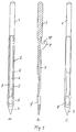
- Figs. 1, 2 show a tufting needle with a shank, 1, a stem, 2, a tip, 3, and an eye, 4, located close to the tip, 3.
- the shank, 1, can be fitted separately in the needle bar of a tufting machine. Alternatively, it can also be embedded in a module body, which holds several identical needles and can then be assigned as a unit to a needle bar.
- the stem, 2, incorporates a thread-guiding groove, 5, which has a flat base, 6.
- Two cheeks, 7, 8, run along the sides of the thread-guiding groove, 5.
- one of these cheeks is provided with a hook-shaped element, 9, which forms a thread support which is open in the direction of the shank, 1.
- the thread support, 10, extends into the area of the thread-guiding groove, 5, and may extend to the latter's base, 6 (Fig. 2).
- the rear view of the tufting needle corresponds to an established configuration, as shown in Figs. 1c, 2c.
- the thread is not supplied to the eye, 4, at an angle to the needle's axis, but is inserted via the thread support, 10, directly into the thread-guiding groove, in which it is guided up to the eye, 4.
- This principle means that the thread is supplied to the needle in the vicinity of the shank, 1, and, subsequently, close to the point at which the tufting needle is mounted on the equipment concerned, that is, at a point at which the occurring forces can be easily discharged into the needle bar.
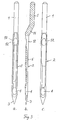
- the embodiment of the invention in accordance with Fig. 3 also has a shank, 1, a stem, 2, a tip, 3, and an eye, 4.
- Fig. 2b shows, in this embodiment the stem, 2, is joined to the shank, 1, via a transitional segment, 11.
- Shank, 1, and stem, 2, are offset in parallel with one another.
- An opening, 12, leads into the upper area of the thread-guiding groove, 5, forming a thread-feeding element.
- the stem, 2, possesses a thickened area, 13, around the opening, 12, which runs transversely to the longitudinal direction of the row of needles when the tufting needle is installed in a needle bar, i.e. it does not intrude into the space between neighbouring needles.
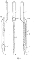
- the embodiment of the invention in accordance with Fig. 10 also has a shank, 1, a stem, 2, a tip, 3, and an eye, 4.
- the stem, 2 is joined to the shank, 1, via a forwardly extending (i.e. away from the needle bar) transitional segment, 90.
- Shank, 1, and stem, 2 are offset in parallel with one another.
- an upwardly and/or forwardly extending opening, 91 is provided which leads into the upper area of the thread guiding groove, 5.
- the upper needle guide can be relatively large (i.e. the width of the needle or larger). Threading is also easier because the yarn can be pushed or pulled down through the upper needle guide into the needle groove toward the needle eye from the relatively clear space above the upper needle guide.
- the upper needle guide of this embodiment incorporates the last guide bar on the tufting machine in a similar orientation, but located directly at the top of the yarn protection groove. Accordingly all of the same space considerations and hole size considerations that apply to the guide bar also apply to the upper needle guide.
- a transitional segment, 14, is provided between the shank, 1, and the stem, 2, with an opening, 15, which serves as a thread-feeding element.
- the shank, 1, and stem, 2, are offset in parallel with one another.
- the opening, 15, is followed by the thread-guiding groove, 5, on the stem, 2, whereby the straight continuation of the thread-guiding groove, 5, is aligned with the opening, 15.
- shank, 1, and stem, 2 are coaxially aligned. Between these two segments of the needle there is a bend, 20, which lies on a plane parallel with the base, 6, of the thread-guiding groove. When this tufting needle is installed in a bar, this bend protrudes transversely to the row of needles, which means that it does not require any additional space between neighbouring tufting needles in the needle row.
- the bend, 20, incorporates an opening, 21, which serves as a thread-feeding element.
- the opening, 21, is twisted at an angle of 90° to the eye, 4.
- the upper end, 22, of the thread-guiding groove, 5, extends up to the opening, 21, in the area of the bend. After passing through the opening, 21, a thread which is fed in through the opening, 21, is thus positioned against a cheek, 23, of the thread-guiding groove, 5, at the upper end of which it continuously takes on the straight course of the thread-guiding groove, 5.
- the shank, 1, and stem, 2 are offset in parallel with one another. Between these segments there is a transitional segment, 30, incorporating an opening, 31, which serves as a thread-feeding element.
- This feeding element is flat, as a result of which the opening is inclined forwards when the row of needles is in installed state, thus simplifying the introduction and course of a thread in this opening.
- the opening, 31, is followed directly by a thread-guiding groove, 5, on the stem, 2.
- Fig. 7 shows an embodiment of the invention in which the thread-feeding elements are provided not directly on a tufting needle, but in a perforated plate which closely adjoins the needle or needles.
- the tufting needles, 55 are firmly embedded in a row in a module body, 56, which, in turn, can be fixed to a needle bar (not shown).
- Attached to the module body, 56 is a plate-type element, 57, the bottom part of which takes the form of a perforated plate, 58.
- This perforated plate, 58 is provided with openings, 59, which serve as thread-feeding elements, whereby one opening, 59, is provided for each tufting needle, 55, and a thread can be passed through these holes and thus conveyed into position in the direct vicinity of the upper area of the thread-guiding groove of the tufting needle concerned.
- the perforated plate, 58 may also constitute a homogeneous element of the module body, 56.
- a plate-type element, 65 is provided on the module body, 56, whereby the bottom part of this element takes the form of a perforated plate, 66.
- the openings in this perforated plate are open to the bottom left (67), to facilitate the introduction of a thread.
- the plate-type element, 65 can be swivelled around a pin, 68.
- a spring, 69 presses it against the module body and consequently into the desired position in relation to the row of needles.
- the spring, 69 is stayed by a counterplate, 70, which is fixed to the module body, 56.
- tufting needles, 75 are fixed individually in a needle bar, 76.
- a perforated plate, 77 Connected to the needle bar, 76, is a perforated plate, 77, each hole, 78, of which is positioned in relation to the thread-guiding groove of a tufting needle, 75, in such a manner as to enable a thread to be fed directly into this groove.
- the thread guideways and guide elements are smoothed and rounded in all embodiments.
- the tufting needles can be designed in accordance with previously common configurations in the area of the tip. The same applies with regard to the side of the needles facing the thread-guiding groove, which is referred to above as the rear side.
Landscapes
- Engineering & Computer Science (AREA)
- Chemical & Material Sciences (AREA)
- Materials Engineering (AREA)
- Textile Engineering (AREA)
- Sewing Machines And Sewing (AREA)
- Knitting Machines (AREA)
Claims (7)
- Aiguille à touffeter en tant qu'aiguille individuelle et en tant qu'élément d'un module d'aiguilles englobant plusieurs aiguilles de ce type, comprenant un talon (1) et une tige (2) avec un chas inférieur (4) prévu dans la région de la pointe (3) de la tige (2) et une rainure de guidage (5) du fil sur un côté de l'aiguille, commençant au niveau du chas (4) et courant le long de la tige (2) de l'aiguille, dans laquelle la rainure de guidage (5) du fil est pourvue d'une ouverture supérieure (15, 21, 31, 91) d'alimentation en fil, caractérisée en ce que l'ouverture supérieure (15, 21, 31, 91) est située dans un segment supérieur de transition (14, 20, 30, 90) du talon (1) pour introduire le fil dans cette rainure, le segment de transition (14) étant situé entre la tige (2) et le talon (1) et la tige (2) étant décalée par rapport au talon (1).
- Aiguille à touffeter selon la revendication 1, caractérisée en ce que les distances entre la région épaissie et la pointe (3) de l'aiguille diffèrent pour les aiguilles pourvues d'une région épaissie dans le plan de la rainure de guidage (5) du fil dans le but de loger un élément d'alimentation en fil.
- Aiguille à touffeter selon la revendication 1, caractérisée en ce qu'elle fonctionne conjointement avec une plaque perforée (58, 66, 77) fixée à la barre d'aiguille d'une machine à touffeter, ladite plaque possédant des trous correspondant à l'extrémité supérieure de la rainure de guidage (5) du fil de chaque aiguille.
- Module d'aiguilles avec aiguille à touffeter selon la revendication 1, caractérisé en ce que les éléments d'alimentation en fil des aiguilles du module prennent la forme des trous d'une plaque perforée (58, 66, 77) qui est située juste au-dessus des aiguilles et dont chaque trou correspond à l'extrémité supérieure d'une rainure de guidage (5) du fil.
- Module d'aiguilles selon la revendication 4, caractérisé en ce que la plaque perforée est fixée à un corps de module.
- Module d'aiguilles selon la revendication 4, caractérisé en ce que la plaque perforée sur le corps de module est montée de telle manière qu'elle puisse être écartée des aiguilles.
- Module d'aiguilles selon une des revendications 4 à 6, caractérisé en ce que les trous de la plaque perforée sont pourvus de fentes pour faciliter l'introduction du fil.
Priority Applications (2)
| Application Number | Priority Date | Filing Date | Title |
|---|---|---|---|
| DE69735842T DE69735842T2 (de) | 1997-06-03 | 1997-06-03 | Tuftingnadel |
| EP19970108895 EP0882831B1 (fr) | 1997-06-03 | 1997-06-03 | Aiguille à touffeter |
Applications Claiming Priority (1)
| Application Number | Priority Date | Filing Date | Title |
|---|---|---|---|
| EP19970108895 EP0882831B1 (fr) | 1997-06-03 | 1997-06-03 | Aiguille à touffeter |
Publications (2)
| Publication Number | Publication Date |
|---|---|
| EP0882831A1 EP0882831A1 (fr) | 1998-12-09 |
| EP0882831B1 true EP0882831B1 (fr) | 2006-05-10 |
Family
ID=8226867
Family Applications (1)
| Application Number | Title | Priority Date | Filing Date |
|---|---|---|---|
| EP19970108895 Expired - Lifetime EP0882831B1 (fr) | 1997-06-03 | 1997-06-03 | Aiguille à touffeter |
Country Status (2)
| Country | Link |
|---|---|
| EP (1) | EP0882831B1 (fr) |
| DE (1) | DE69735842T2 (fr) |
Families Citing this family (3)
| Publication number | Priority date | Publication date | Assignee | Title |
|---|---|---|---|---|
| GB9825978D0 (en) * | 1998-11-27 | 1999-01-20 | Cobble Blackburn Ltd | An improved needle for a tufting machine |
| DE19921914C2 (de) | 1999-05-12 | 2001-10-25 | Groz Beckert Kg | Nähmaschinennadel mit versetzten Öhrstegen |
| GB2361248B (en) * | 2000-04-10 | 2003-08-27 | Cobble Blackburn Ltd | A needle for a tufting machine |
Family Cites Families (7)
| Publication number | Priority date | Publication date | Assignee | Title |
|---|---|---|---|---|
| US1450101A (en) * | 1920-06-01 | 1923-03-27 | Wilfred B Mathewson | Needle for tufting machines |
| US3442233A (en) * | 1965-01-07 | 1969-05-06 | Lewis Card & Co Inc | Yarn guide for a tufting needle |
| US3618542A (en) * | 1970-03-20 | 1971-11-09 | Singer Co | Multineedle unit |
| US3641956A (en) * | 1970-08-26 | 1972-02-15 | Sylvan B Ownbey | Nondirectional loop tuft carpet-making machine |
| GB1601812A (en) * | 1977-03-09 | 1981-11-04 | Johansson A | Tufting |
| DE8436630U1 (de) * | 1984-12-14 | 1986-05-28 | Fa. Jos. Zimmermann, 5100 Aachen | Maschinennadel, insbesondere Tuftingnadel |
| DE19528152C1 (de) * | 1995-08-01 | 1996-11-07 | Zimmermann Jos Gmbh & Co Kg | Paarung von Tuftingnadeln für die Drei-Achsen-Tuftingtechnik |
-
1997
- 1997-06-03 DE DE69735842T patent/DE69735842T2/de not_active Expired - Lifetime
- 1997-06-03 EP EP19970108895 patent/EP0882831B1/fr not_active Expired - Lifetime
Also Published As
| Publication number | Publication date |
|---|---|
| DE69735842D1 (de) | 2006-06-14 |
| DE69735842T2 (de) | 2007-04-19 |
| EP0882831A1 (fr) | 1998-12-09 |
Similar Documents
| Publication | Publication Date | Title |
|---|---|---|
| CA1090658A (fr) | Machine a boucler permettant la coupe selective des boucles sur une meme piqure | |
| CA2058987C (fr) | Methode et appareil de fabrication de produits textiles a partir de fibres et (ou) de filaments, et produits ainsi obtenus | |
| US4103629A (en) | Looper apparatus for forming cut pile and loop pile in the same row of stitching in a narrow gauge tufting machine | |
| US5189966A (en) | Tufting apparatus and method for forming loop pile | |
| CA1188932A (fr) | Machines a boucler a crochets opposes pour la fabrication de tissus touffus | |
| US4274346A (en) | Cut pile looper | |
| EP0882831B1 (fr) | Aiguille à touffeter | |
| US3929082A (en) | Needles for tufting or the like | |
| CS207468B1 (en) | woven belt method of manufacturing same and a small-ware weaving loom for carrying out the method | |
| US4195584A (en) | Tufting needle | |
| EP3987100B1 (fr) | Module de pied presseur pour machine à touffeter | |
| EP0156503A1 (fr) | Fil à coudre comprenant une matière thermoplastique; procédé de couture et produit obtenu | |
| KR20160056903A (ko) | 직기용 귀부 파지 장치, 직기 및 직물의 제조 방법 | |
| KR100433313B1 (ko) | 접착된피륙을바느질하는장치 | |
| US3443534A (en) | Tufting machines | |
| US6062151A (en) | Tufting needle with offset stem | |
| US6230638B1 (en) | System for directional air enhancement of a textile tufting machine | |
| JPH0327157A (ja) | 少くとも1つの糸ガイドを有する丸編機用の給糸装置 | |
| CN105713531B (zh) | 具有长纤维缝编无纺布的胶粘带 | |
| CN101294332B (zh) | 具有弹力纱的喂纱功能的针织机 | |
| US3442233A (en) | Yarn guide for a tufting needle | |
| JPH1161607A (ja) | リブを有する布帛の誘導装置 | |
| US5467724A (en) | Yarn jerker and threader guide for tufting machines | |
| US6152055A (en) | Tufting machine needle | |
| US3356049A (en) | Fluid flow method and apparatus for applying twist to strand material |
Legal Events
| Date | Code | Title | Description |
|---|---|---|---|
| PUAI | Public reference made under article 153(3) epc to a published international application that has entered the european phase |
Free format text: ORIGINAL CODE: 0009012 |
|
| AK | Designated contracting states |
Kind code of ref document: A1 Designated state(s): BE DE GB NL |
|
| 17P | Request for examination filed |
Effective date: 19990607 |
|
| AKX | Designation fees paid |
Free format text: BE DE GB NL |
|
| 17Q | First examination report despatched |
Effective date: 20001205 |
|
| RAP1 | Party data changed (applicant data changed or rights of an application transferred) |
Owner name: GROZ-BECKERT KG |
|
| GRAP | Despatch of communication of intention to grant a patent |
Free format text: ORIGINAL CODE: EPIDOSNIGR1 |
|
| GRAS | Grant fee paid |
Free format text: ORIGINAL CODE: EPIDOSNIGR3 |
|
| GRAA | (expected) grant |
Free format text: ORIGINAL CODE: 0009210 |
|
| AK | Designated contracting states |
Kind code of ref document: B1 Designated state(s): BE DE GB NL |
|
| REG | Reference to a national code |
Ref country code: GB Ref legal event code: FG4D |
|
| REF | Corresponds to: |
Ref document number: 69735842 Country of ref document: DE Date of ref document: 20060614 Kind code of ref document: P |
|
| PLBE | No opposition filed within time limit |
Free format text: ORIGINAL CODE: 0009261 |
|
| STAA | Information on the status of an ep patent application or granted ep patent |
Free format text: STATUS: NO OPPOSITION FILED WITHIN TIME LIMIT |
|
| 26N | No opposition filed |
Effective date: 20070213 |
|
| PGFP | Annual fee paid to national office [announced via postgrant information from national office to epo] |
Ref country code: GB Payment date: 20160601 Year of fee payment: 20 |
|
| PGFP | Annual fee paid to national office [announced via postgrant information from national office to epo] |
Ref country code: BE Payment date: 20160425 Year of fee payment: 20 Ref country code: NL Payment date: 20160610 Year of fee payment: 20 |
|
| PGFP | Annual fee paid to national office [announced via postgrant information from national office to epo] |
Ref country code: DE Payment date: 20160630 Year of fee payment: 20 |
|
| REG | Reference to a national code |
Ref country code: DE Ref legal event code: R071 Ref document number: 69735842 Country of ref document: DE |
|
| REG | Reference to a national code |
Ref country code: NL Ref legal event code: MK Effective date: 20170602 |
|
| REG | Reference to a national code |
Ref country code: GB Ref legal event code: PE20 Expiry date: 20170602 |
|
| PG25 | Lapsed in a contracting state [announced via postgrant information from national office to epo] |
Ref country code: GB Free format text: LAPSE BECAUSE OF EXPIRATION OF PROTECTION Effective date: 20170602 |