EP0882920A1 - Mitigeur sanitaire à dispositif à thermostat - Google Patents
Mitigeur sanitaire à dispositif à thermostat Download PDFInfo
- Publication number
- EP0882920A1 EP0882920A1 EP98111432A EP98111432A EP0882920A1 EP 0882920 A1 EP0882920 A1 EP 0882920A1 EP 98111432 A EP98111432 A EP 98111432A EP 98111432 A EP98111432 A EP 98111432A EP 0882920 A1 EP0882920 A1 EP 0882920A1
- Authority
- EP
- European Patent Office
- Prior art keywords
- cartridge housing
- snap ring
- mixer tap
- seal
- cartridge
- Prior art date
- Legal status (The legal status is an assumption and is not a legal conclusion. Google has not performed a legal analysis and makes no representation as to the accuracy of the status listed.)
- Granted
Links
- 239000012528 membrane Substances 0.000 claims abstract description 9
- 230000001105 regulatory effect Effects 0.000 claims description 3
- 230000006835 compression Effects 0.000 description 12
- 238000007906 compression Methods 0.000 description 12
- 230000005540 biological transmission Effects 0.000 description 3
- XLYOFNOQVPJJNP-UHFFFAOYSA-N water Substances O XLYOFNOQVPJJNP-UHFFFAOYSA-N 0.000 description 3
- 230000015572 biosynthetic process Effects 0.000 description 1
- 238000005352 clarification Methods 0.000 description 1
- 238000010276 construction Methods 0.000 description 1
- 230000000694 effects Effects 0.000 description 1
- 230000037431 insertion Effects 0.000 description 1
- 238000003780 insertion Methods 0.000 description 1
- 230000002093 peripheral effect Effects 0.000 description 1
- 238000007789 sealing Methods 0.000 description 1
Images



Classifications
-
- E—FIXED CONSTRUCTIONS
- E03—WATER SUPPLY; SEWERAGE
- E03C—DOMESTIC PLUMBING INSTALLATIONS FOR FRESH WATER OR WASTE WATER; SINKS
- E03C1/00—Domestic plumbing installations for fresh water or waste water; Sinks
- E03C1/02—Plumbing installations for fresh water
- E03C1/04—Water-basin installations specially adapted to wash-basins or baths
-
- G—PHYSICS
- G05—CONTROLLING; REGULATING
- G05D—SYSTEMS FOR CONTROLLING OR REGULATING NON-ELECTRIC VARIABLES
- G05D23/00—Control of temperature
- G05D23/01—Control of temperature without auxiliary power
- G05D23/13—Control of temperature without auxiliary power by varying the mixing ratio of two fluids having different temperatures
- G05D23/1306—Control of temperature without auxiliary power by varying the mixing ratio of two fluids having different temperatures for liquids
- G05D23/132—Control of temperature without auxiliary power by varying the mixing ratio of two fluids having different temperatures for liquids with temperature sensing element
- G05D23/134—Control of temperature without auxiliary power by varying the mixing ratio of two fluids having different temperatures for liquids with temperature sensing element measuring the temperature of mixed fluid
- G05D23/1346—Control of temperature without auxiliary power by varying the mixing ratio of two fluids having different temperatures for liquids with temperature sensing element measuring the temperature of mixed fluid with manual temperature setting means
Definitions
- the invention relates to a sanitary mixer tap with a thermostat, with a Thermostat cartridge, with a control body arranged in a cartridge housing and with a seal arranged in a groove of the control body, in particular a membrane seal.
- a disadvantage of the mixer tap known from practice that described above Art is that the control body easily in the disassembled state from the cartridge housing can fall out. This can make assembly and disassembly more difficult. In addition, the control body can fall out of the cartridge housing to be damaged. This applies in particular to the control edges one to the Regulating body belonging control sleeve or one connected to the control sleeve Expansion element.
- the invention goes a new way and avoids the disadvantages mentioned above in that a snap ring that can be locked with the cartridge housing for holding of the control body is provided in the cartridge housing.
- a snap ring that can be locked with the cartridge housing for holding of the control body is provided in the cartridge housing.
- the cartridge housing and the regulating body form a seemingly simple measure a jointly manageable unit that is easily assembled and disassembled or can be replaced.
- the rule body becomes captive in Cartridge housing held without the function of the control body in the cartridge housing is hindered by the snap ring.
- the snap ring is in the locked state the seal indirectly or directly, forming a seal stop is present.
- the front edge of the Snap rings have a bevel.
- the snap ring then has an additional sealing function. All in all In this embodiment, there is a maintenance-free seal that is above is also fatless.
- an annular sieve is connected to the snap ring is.
- the sieve and the snap ring should be made in one piece which is particularly useful when the snap ring and strainer are out Plastic, especially made of POM.
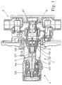
- a sanitary mixer tap 1 is shown with a thermostat, which in a wall mounting housing 2 is screwed in.
- the sanitary mixer tap 1 has one Thermostat cartridge 3, a temperature adjustment device 4, an extension device 5 and a reset device 6.
- the thermostatic cartridge 3 has a cartridge housing 7 in which on the one hand a control body 8 and on the other an overtravel unit 9 is accommodated.
- the cartridge housing 7 has a first larger, outwardly open chamber 10 for the control body 8 and a smaller one second chamber 11 for the overtravel unit 9.
- the chambers 10, 11 are over a sealed opening 12 connected to each other, in which a pressure rod 13 is mounted.
- the pressure rod 13 stands both with the control body 8 and with the overtravel unit 9 in connection.
- the overtravel unit 9 has a sleeve body 14, a compression spring element 15 and Pressure piece 16 on.
- the compression spring element 15, which is a coil spring acts is arranged together with the pressure piece 16 within the sleeve body 14.
- the arrangement is such that the compression spring element 15 against the Pressure piece 16 acts.
- the pressure piece 16 has a peripheral edge 17 on which the compression spring element 15 rests.
- the pressure piece 16, which is basically could be designed as a plate, has an outer pin shape and takes the Push rod 13 on.
- a corresponding receptacle 18 is provided in the pressure piece 16.
- the sleeve body 14 has a stop at each of its two ends 19, 20 as a circumferential stop collar.
- One stop 19 serves as an abutment for the pressure piece 16, the other stop 20 as an abutment for the compression spring element 15.
- the sleeve body 14 consists in the illustrated embodiment of two identical Shells 21, 22. Since the shells 21, 22 are not only identical in construction, but two Represent separate components from each other, means the previously mentioned expression "hinged” also means that one shell can be removed from the other so that the by the stops 19, 20 limited interior space of the sleeve body 14 for insertion the compression spring element 15 and the pressure piece 16 is freely accessible.
- the Pressure piece 16 and the shells 21, 22 consist of plastic, in particular POM.
- the front circumferential end edge 23 on the chamber 11 becomes as far inward flanged out that the overtravel unit 9 is secured in the chamber 11 and cannot be pushed out.
- the control body 8 already mentioned has a control sleeve 24 and an expansion element 25, with the expansion element 25 attached to the control sleeve 24 is.
- the control sleeve 24 itself has a control edge 26, 27 at its ends Control of the flow of cold and hot water.
- On the outside of the Control sleeve 24 of the control body 8 is a circumferential membrane seal 28.
- the membrane seal 28 is arranged in a V-shaped groove 29 of the control sleeve 24 and separates the hot water area from the cold water area.
- a snap ring which can be locked with the cartridge housing 7 30 is provided, which for holding the control body 8 in the cartridge housing 7, d. H. serves in the chamber 10.
- the cartridge housing 7 has an opening side in the chamber 10 a preferably circumferential, projecting inward Edge 31, while at least one latching projection 32 on the snap ring 30 is provided with usual ramp.
- the snap connection between the cartridge housing 7 and the snap ring 30 is such that after snapping the snap ring 30, which is held on the cartridge housing 7 essentially without play, d. H. is not displaceable in the direction of the longitudinal axis L.
- the Snap ring 30 in the locked state on the membrane seal 28 with formation a seal stop immediately.
- the snap ring 30 does not worry only for the fact that the cartridge housing 7 and the control body 8 have one in common form manageable unit, but it also serves to realize the seal between these two components.
- the front facing the membrane seal 28 Front edge 33 has a bevel 34.
- an annular sieve 35 is connected to the snap ring 30 extends beyond the control edge 27 of the control sleeve 24. But otherwise the control edge 26 is also preceded by a sieve 36 which is connected to the cartridge housing 7 connected is. In contrast to the sieve 3.6, the sieve 35 is in one piece with the snap ring 30 trained. The entire assembly consists of snap ring 30 and sieve 35 made of plastic, especially POM.
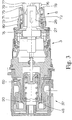
- the adjustment unit 37 has a mounting element 38, a screw element 39 and a rotating element 40.
- the attachment element 38 is designed in this way. that it is in the assembled state against rotation and also pull-proof on the Cartridge housing 7 or the extension device 5 can be placed.
- fixing means 42 are provided with corresponding.
- Fixing means (not shown) on the cartridge housing 7 correspond.
- the fixing means on the attachment element 38 by approximately sawtooth-shaped projections.
- the interior 41 itself is approximately adapted to the shape of the area of the cartridge housing 7, on which the attachment element 38 is placed.
- a neck 43 is provided which has a circumferential cone 44.
- a circumferential groove 45 is provided on the cone 44.
- the attachment element has 38 has an external thread 46 with an internal thread 47 in the screw element 39 corresponds.
- the screw element 39 has a circumferential, inwardly projecting edge 48 provided central opening 49.
- 39 are elongated on the outside of the screw element and approximately in Guide projections aligned in the direction of the longitudinal axis L of the adjusting unit 37 50 provided. those with corresponding guide projections 51 on the inside of the rotating element 40 correspond.
- the rotating element 40 is also one provided central opening 52 having edge 53 which projects inwards and can protrude into the opening 49. This means that the outer dimensions of the edge 53 are slightly smaller than the internal dimensions of the opening 49.
- the adjusting unit 37 preferably as a structural unit on the Cartridge housing 7 or an extension housing 54 of the extension device 5 can be snapped on. If an extension housing 54 is used, as shown in FIG. 1 is illustrated, it is understood that the extension housing 54 on its the cartridge housing 7 opposite end of the outer shape of the corresponding end corresponds to the cartridge housing 7.
- the extension device 5 itself, as can be seen from FIG. 1, only exists in itself from the extension housing 54 and a slidable arranged therein Transmission element 55, which the adjusting unit 37 with the overtravel unit 9 connects.
- a first edge 56 is provided on the transmission element 55 communicates with the edge 48 of the screw element 39 while the other Edge 57 is connected to the stop 20. In this way, a rotational movement of the rotating element 40 via the screw element 39, the transmission element 55, the overstroke unit 9, the push rod 13 on the control element 8 for temperature adjustment be transmitted.
- a separate latch 58 has the advantage that the latching is particularly simple Way can be solved again, which cannot, at least not without the risk that Locking elements are damaged, is possible if the effecting the locking Elements are not accessible or removable from the outside.
- the receptacle 59 has two on opposite Provided openings 60, which extend into the inner region 41 of the Extension element 38 or the extension housing 54 extend into it. Through the Openings 60 each protrude a portion of the latch 58 to the groove 45 in To cooperate cartridge housing 7 or in the extension housing 54.
- the Bolt 58 itself is U-shaped and has two opposite one another Locking leg 61, 62 on.
- a fixing section closes at one locking leg 61 63, which for releasably holding the latch 58 on the attachment element 38 or the extension housing 54 is used.
- the latch 58 has one Handle section 64, which is used for easy removal of the latch 58.
- the latch 58 otherwise consists of plastic, especially POM.
- the rotary element 40 is so that the adjusting unit 37 can be handled as a structural unit Secured rotatably on the attachment element 38 via a further separate bolt 65.
- the bolt 65 not only secures the rotating element 40 on the mounting element 38, but also limits the movement of the screw element 39 within of the rotating element 40. If the further bolt 65 were not present, it could Rotating element 40 are unscrewed from the mounting element 38.
- Receptacle 66 is provided for the further bolt 65, the receptacle 66 being two Openings opening into the inner region of the rotating element 40 67, through which a section of the further bolt 65 in the inserted state protrudes into the interior. These sections protruding into the interior further latch 65 act with a corresponding circumferential Groove 68 on the mounting element 38 together.
- the further bolt 65 is also U-shaped educated; it therefore has two legs 69, 70.
- the latch 65 On each of the two legs 69, 70, the latch 65 has a fixing section 71 'pointing outwards.
- the Fixing sections 71 ' serve to releasably hold the further bolt 65 on the rotary element 40 or in the recording 66.
- the reset device 6 is shown in more detail during it can be seen in Fig. I in the installed state of the mixer tap 1.
- the further pressure piece 72nd serves to interact with the expansion element 25 of the control body 8.
- one the other compression spring element 71 and the other Pressure piece 72 receiving sleeve 73 is provided as a separate component.
- the front end edge 74 of the sleeve 73 is the valve seat of the control edge 27 Control sleeve 24 formed.
- the sleeve 73, the other compression spring element 71 and the further pressure piece 72 formed as a structural unit, that is, together manageable.
- the further pressure piece 72 is locked with the sleeve 73.
- the Arrangement of the further pressure spring element 71 and the further pressure piece 72 in the sleeve 73 is such that the sleeve 73 facing away from the control body 8 End preferably a circumferential, inwardly directed stop 75th having.
- the further compression spring element 71 lies on the inside against the stop 75 on.
- the further pressure piece 72 is pushed through the further pressure spring element 71 and locked behind the stop 75.
- For locking is on the outside at least one locking projection 76 is provided on the further pressure piece 72.
- the further pressure piece 72 also has a sleeve-like shape per se and forms at the end a stop 77 for the expansion element 25. In the illustrated embodiment is the area forming the stop 77 of a total of four, each over formed a slot 78 spaced arms 79.
- the further Pressure piece 72 is preferably made of plastic, in particular POM.
- the sleeve 73 On the outside, the sleeve 73 has an external thread 80 which mates with a corresponding one Internal thread in the wall mounting housing 2 corresponds. Still is a seal 81 is mounted in the rear region of the sleeve 73.
- the sanitary mixer tap 1 with a thermostat device shown in FIG. 1 is simpler Way to assemble. First, the reset device 6 in the wall mounting housing 2 screwed in. Then the thermostatic cartridge 3 with the control body 8 fixed via the snap ring 30 into the wall mounting housing 2 screwed in. Then the extension device 5 on the neck 43 of the Cartridge housing 7 are pushed on, the latch 58 after the movement engages in the groove 45 via the cone 44. You can then do the same Way the adjustment unit 37 is pushed onto the neck of the extension housing 45 until the latch 58 engages.
Landscapes
- Engineering & Computer Science (AREA)
- Physics & Mathematics (AREA)
- Life Sciences & Earth Sciences (AREA)
- Hydrology & Water Resources (AREA)
- Public Health (AREA)
- Water Supply & Treatment (AREA)
- Health & Medical Sciences (AREA)
- General Physics & Mathematics (AREA)
- Automation & Control Theory (AREA)
- Domestic Plumbing Installations (AREA)
- Temperature-Responsive Valves (AREA)
- Battery Mounting, Suspending (AREA)
- Multiple-Way Valves (AREA)
Applications Claiming Priority (3)
| Application Number | Priority Date | Filing Date | Title |
|---|---|---|---|
| DE19502147A DE19502147C2 (de) | 1995-01-25 | 1995-01-25 | Sanitäre Mischbatterie mit Thermostateinrichtung |
| DE19502147 | 1995-01-25 | ||
| EP96901759A EP0805928B1 (fr) | 1995-01-25 | 1996-01-24 | Mitigeur sanitaire a dispositif a thermostat |
Related Parent Applications (1)
| Application Number | Title | Priority Date | Filing Date |
|---|---|---|---|
| EP96901759.9 Division | 1996-08-01 |
Publications (2)
| Publication Number | Publication Date |
|---|---|
| EP0882920A1 true EP0882920A1 (fr) | 1998-12-09 |
| EP0882920B1 EP0882920B1 (fr) | 2003-06-04 |
Family
ID=7752230
Family Applications (4)
| Application Number | Title | Priority Date | Filing Date |
|---|---|---|---|
| EP98111431A Revoked EP0875703B1 (fr) | 1995-01-25 | 1996-01-24 | Mitigeur sanitaire à dispositif à thermostat |
| EP98111433A Expired - Lifetime EP0875704B1 (fr) | 1995-01-25 | 1996-01-24 | Mitigeur sanitaire à dispositif à thermostat |
| EP96901759A Expired - Lifetime EP0805928B1 (fr) | 1995-01-25 | 1996-01-24 | Mitigeur sanitaire a dispositif a thermostat |
| EP98111432A Expired - Lifetime EP0882920B1 (fr) | 1995-01-25 | 1996-01-24 | Mitigeur sanitaire à dispositif à thermostat |
Family Applications Before (3)
| Application Number | Title | Priority Date | Filing Date |
|---|---|---|---|
| EP98111431A Revoked EP0875703B1 (fr) | 1995-01-25 | 1996-01-24 | Mitigeur sanitaire à dispositif à thermostat |
| EP98111433A Expired - Lifetime EP0875704B1 (fr) | 1995-01-25 | 1996-01-24 | Mitigeur sanitaire à dispositif à thermostat |
| EP96901759A Expired - Lifetime EP0805928B1 (fr) | 1995-01-25 | 1996-01-24 | Mitigeur sanitaire a dispositif a thermostat |
Country Status (5)
| Country | Link |
|---|---|
| US (1) | US5979777A (fr) |
| EP (4) | EP0875703B1 (fr) |
| DE (5) | DE19502147C2 (fr) |
| ES (4) | ES2201373T3 (fr) |
| WO (1) | WO1996023157A1 (fr) |
Families Citing this family (24)
| Publication number | Priority date | Publication date | Assignee | Title |
|---|---|---|---|---|
| FR2774740B1 (fr) * | 1998-02-11 | 2000-05-05 | Vernet Sa | Cartouche de securite pour mitigeur thermostatique |
| DE10045595A1 (de) * | 2000-09-15 | 2002-03-28 | Hansgrohe Ag | Thermostatventil |
| DE10048044A1 (de) | 2000-09-29 | 2002-04-25 | Ideal Standard | Sanitäre Mischbatterie |
| DE10109644A1 (de) * | 2001-02-27 | 2002-09-26 | Behr Thermot Tronik Gmbh | Vorrichtung zum Anbringen eines Stellantriebes oder eines Thermostatkopfes an einem Ventil |
| DE10114357A1 (de) * | 2001-03-22 | 2002-09-26 | Hansgrohe Ag | Termostatisch gesteuertes Mischventil |
| US6604687B2 (en) * | 2001-07-17 | 2003-08-12 | Marks Controls Corporation | Thermal fluid control valve |
| US7717351B2 (en) | 2001-08-24 | 2010-05-18 | Margarl, LLC | Mixing valve |
| DE10153988B4 (de) * | 2001-11-06 | 2011-07-21 | Grohe AG, 58675 | Sollwerteinstellvorrichtung an einem thermostatisch geregelten Mischventil |
| US6676024B1 (en) | 2002-09-05 | 2004-01-13 | Masco Corporation | Thermostatic valve with electronic control |
| JP2005188671A (ja) * | 2003-12-26 | 2005-07-14 | San-Ei Faucet Mfg Co Ltd | 湯水混合水栓 |
| US7913926B2 (en) * | 2006-02-17 | 2011-03-29 | Watts Water Technologies, Inc. | Thermostatic mixing valve |
| FR2921709A1 (fr) * | 2007-09-27 | 2009-04-03 | Vernet Sa | Mitigeur thermostatique et procede de fabrication d'un tel mitigeur. |
| DE102007049089B4 (de) * | 2007-10-11 | 2014-09-04 | Grohe Ag | Thermostatventil mit einem einstellbarem Regelspalt |
| US9376789B2 (en) | 2011-03-08 | 2016-06-28 | As Ip Holdco, Llc | Quick connection coupling |
| US10260642B2 (en) | 2011-04-26 | 2019-04-16 | As Ip Holdco, Llc | Faucet valve cartridge |
| CA2846254C (fr) | 2011-08-24 | 2019-09-17 | As Ip Holdco, Llc | Ensemble de robinets a ecartement pouvant etre installe sans outils, trousses et procedes d'installation |
| US9504970B2 (en) | 2011-10-22 | 2016-11-29 | Magarl, Llc | Methods and apparatus for creating turbulence in a thermostatic mixing valve |
| DE102013010412B4 (de) * | 2013-06-21 | 2015-09-10 | Hansa Metallwerke Ag | Sanitäre Thermostatarmatur |
| TR201816323T4 (tr) | 2015-08-11 | 2018-11-21 | Ideal Standard Int Nv | Zorunlu kılavuz içeren kapaklı termostat valfi. |
| EP3371491B1 (fr) | 2015-11-05 | 2022-01-05 | Reliance Worldwide Corporation (Aust.) Pty. Ltd. | Robinet mélangeur thermostatique avec fonctionnalité de désinfection |
| DE102016113511B3 (de) | 2016-07-21 | 2017-11-09 | Ideal Standard International Nv | Thermostatkartusche mit in der Schließstellung fixierter Regelhülse |
| FR3089590B1 (fr) * | 2018-12-06 | 2020-12-25 | Vernet | Cartouche thermostatique pour robinet mitigeur |
| WO2020150462A1 (fr) | 2019-01-18 | 2020-07-23 | Geberit International Ag | Dispositif anti-brûlure pour système d'alimentation en fluide ayant une désinfection d'eau chaude |
| DE102019105518A1 (de) | 2019-03-05 | 2020-09-10 | Grohe Ag | Sieb mit veränderlichem Umfang für ein Thermostatventil |
Citations (3)
| Publication number | Priority date | Publication date | Assignee | Title |
|---|---|---|---|---|
| DE1550412A1 (de) * | 1965-11-09 | 1969-09-25 | Meynell & Sons Ltd | Mischventil |
| EP0461536A2 (fr) * | 1990-06-15 | 1991-12-18 | Friedrich Grohe Aktiengesellschaft | Dispositif de réglage de la valeur de consigne pour une vanne mélangeuse régulée thermostatiquement |
| EP0530471A1 (fr) * | 1991-07-18 | 1993-03-10 | Friedrich Grohe Aktiengesellschaft | Dispositif de commande pour une soupape de mélange |
Family Cites Families (13)
| Publication number | Priority date | Publication date | Assignee | Title |
|---|---|---|---|---|
| DE7421876U (de) * | 1974-09-26 | Neheim Goeke & Co Kg | Thermostatkopf für ein Heizkörperventil | |
| FR2067762A5 (fr) * | 1969-11-15 | 1971-08-20 | Queroy Ets | |
| FR2128943A5 (fr) * | 1971-03-09 | 1972-10-27 | Trubert Denis | |
| IT999835B (it) * | 1973-11-28 | 1976-03-10 | Knapp Alfons | Dispositivo miscelatore termostati co perfezionato per impianti idrau lici |
| DE2852935C2 (de) * | 1978-12-07 | 1982-12-23 | Hansa Metallwerke Ag, 7000 Stuttgart | Thermostatventil |
| DE8024065U1 (de) * | 1980-09-06 | 1980-12-18 | Joh. Vaillant Gmbh U. Co, 5630 Remscheid | Anordnung zur halterung eines temperaturfuehlers |
| CH654090A5 (de) * | 1982-01-11 | 1986-01-31 | Wallisellen Ag Armaturen | Thermostatisch gesteuertes mischventil fuer kalt- und warmwasser. |
| US4607788A (en) * | 1982-05-26 | 1986-08-26 | Meynell Valves Limited | Mixing valve |
| SE467890B (sv) * | 1991-02-01 | 1992-09-28 | Mattsson Ab F M | Reglerenhet till blandarventil med en tryckberoende kolvslid koaxiellt roerlig i foerhaallande till en temperaturberoende reglerventilkaegla |
| DE4141789A1 (de) * | 1991-12-18 | 1993-06-24 | Grohe Armaturen Friedrich | Stellvorrichtung fuer ein mischventil |
| DE4206703A1 (de) * | 1992-03-04 | 1993-09-09 | Grohe Armaturen Friedrich | Mischbatterie |
| DE4225175A1 (de) * | 1992-07-30 | 1994-02-03 | Grohe Armaturen Friedrich | Thermostatgeregeltes Mischventil |
| DE9309447U1 (de) * | 1993-06-25 | 1993-09-16 | Hans Sasserath & Co Kg, 41352 Korschenbroich | Temperaturgesteuertes Dreiwege-Mischventil |
-
1995
- 1995-01-25 DE DE19502147A patent/DE19502147C2/de not_active Expired - Fee Related
-
1996
- 1996-01-24 DE DE59610516T patent/DE59610516D1/de not_active Expired - Fee Related
- 1996-01-24 EP EP98111431A patent/EP0875703B1/fr not_active Revoked
- 1996-01-24 ES ES98111431T patent/ES2201373T3/es not_active Expired - Lifetime
- 1996-01-24 EP EP98111433A patent/EP0875704B1/fr not_active Expired - Lifetime
- 1996-01-24 US US08/875,343 patent/US5979777A/en not_active Expired - Lifetime
- 1996-01-24 WO PCT/EP1996/000276 patent/WO1996023157A1/fr not_active Ceased
- 1996-01-24 DE DE59610512T patent/DE59610512D1/de not_active Expired - Fee Related
- 1996-01-24 DE DE59605442T patent/DE59605442D1/de not_active Expired - Lifetime
- 1996-01-24 EP EP96901759A patent/EP0805928B1/fr not_active Expired - Lifetime
- 1996-01-24 DE DE59610513T patent/DE59610513D1/de not_active Expired - Fee Related
- 1996-01-24 ES ES98111433T patent/ES2201375T3/es not_active Expired - Lifetime
- 1996-01-24 ES ES98111432T patent/ES2201374T3/es not_active Expired - Lifetime
- 1996-01-24 EP EP98111432A patent/EP0882920B1/fr not_active Expired - Lifetime
- 1996-01-24 ES ES96901759T patent/ES2148726T3/es not_active Expired - Lifetime
Patent Citations (3)
| Publication number | Priority date | Publication date | Assignee | Title |
|---|---|---|---|---|
| DE1550412A1 (de) * | 1965-11-09 | 1969-09-25 | Meynell & Sons Ltd | Mischventil |
| EP0461536A2 (fr) * | 1990-06-15 | 1991-12-18 | Friedrich Grohe Aktiengesellschaft | Dispositif de réglage de la valeur de consigne pour une vanne mélangeuse régulée thermostatiquement |
| EP0530471A1 (fr) * | 1991-07-18 | 1993-03-10 | Friedrich Grohe Aktiengesellschaft | Dispositif de commande pour une soupape de mélange |
Also Published As
| Publication number | Publication date |
|---|---|
| EP0875704B1 (fr) | 2003-06-04 |
| DE59610513D1 (de) | 2003-07-10 |
| EP0875703B1 (fr) | 2003-06-04 |
| EP0805928A1 (fr) | 1997-11-12 |
| DE19502147C2 (de) | 1997-11-27 |
| WO1996023157A1 (fr) | 1996-08-01 |
| ES2201375T3 (es) | 2004-03-16 |
| EP0805928B1 (fr) | 2000-06-14 |
| EP0875703A3 (fr) | 1998-11-25 |
| DE19502147A1 (de) | 1996-08-08 |
| EP0875704A2 (fr) | 1998-11-04 |
| DE59610512D1 (de) | 2003-07-10 |
| DE59610516D1 (de) | 2003-07-10 |
| DE59605442D1 (de) | 2000-07-20 |
| EP0875704A3 (fr) | 1998-11-25 |
| ES2148726T3 (es) | 2000-10-16 |
| EP0875703A2 (fr) | 1998-11-04 |
| EP0882920B1 (fr) | 2003-06-04 |
| US5979777A (en) | 1999-11-09 |
| ES2201373T3 (es) | 2004-03-16 |
| ES2201374T3 (es) | 2004-03-16 |
Similar Documents
| Publication | Publication Date | Title |
|---|---|---|
| EP0882920B1 (fr) | Mitigeur sanitaire à dispositif à thermostat | |
| DE3100037C2 (fr) | ||
| EP0621077A1 (fr) | Douche à main | |
| DE4408888A1 (de) | Filter für eine Brennkraftmaschine | |
| EP0044904A2 (fr) | Thermostat pour régler la soupape d'un radiateur | |
| DE3327828C2 (fr) | ||
| DE2537033C2 (de) | An ein Heizkörperventil anschließbarer Thermostat | |
| EP0408785B1 (fr) | Ensemble de béquille pour portes ou fenêtres | |
| DE19961412A1 (de) | Einbaugarnitur mit lösbarer Kuppelmuffenverfbindung | |
| EP0499716A1 (fr) | Robinet mélangeur à levier unique pour installations sanitaires | |
| DE2917006A1 (de) | Verriegelungseinheit fuer tueren oder deckel von gehaeusekoerpern | |
| DE9300841U1 (de) | Sanitärarmatur | |
| DE19961420C2 (de) | Einbaugarnitur mit verbesserter Verrastung | |
| DE3521965A1 (de) | Thermostat fuer heizkoerperventile | |
| LU103110B1 (de) | Zur Frontmontage angepasstes Relais | |
| DE3827757A1 (de) | Einhebelmischbatterie | |
| DE9400583U1 (de) | Manometer, insbesondere für ein Hochdruckreinigungsgerät | |
| EP0788764A1 (fr) | Accouplement pour un otoscope | |
| DE3535176A1 (de) | Anschlussarmatur fuer plattenheizkoerper | |
| DE102005061112B4 (de) | Hülsrohrglocke mit Adapter | |
| DE10048044A1 (de) | Sanitäre Mischbatterie | |
| CH440887A (de) | Hahn | |
| DE10305234B4 (de) | Riegelverschlusseinsatz zur Anbringung in einer gehäuseartigen Aufnahme in einer abnehmbaren, zahntechnischen Prothese | |
| DE686134C (de) | Zusatzvorrichtung zur Durchfuehrung langer Belichtungen bei photographischen Aufnahmen | |
| DE102004055881A1 (de) | Sanitäre Unterputzarmatur mit einer Unterputzabdeckplatte |
Legal Events
| Date | Code | Title | Description |
|---|---|---|---|
| PUAI | Public reference made under article 153(3) epc to a published international application that has entered the european phase |
Free format text: ORIGINAL CODE: 0009012 |
|
| 17P | Request for examination filed |
Effective date: 19980720 |
|
| AC | Divisional application: reference to earlier application |
Ref document number: 805928 Country of ref document: EP |
|
| AK | Designated contracting states |
Kind code of ref document: A1 Designated state(s): BE DE ES FR IT LU NL SE |
|
| 17Q | First examination report despatched |
Effective date: 20010926 |
|
| GRAH | Despatch of communication of intention to grant a patent |
Free format text: ORIGINAL CODE: EPIDOS IGRA |
|
| RAP1 | Party data changed (applicant data changed or rights of an application transferred) |
Owner name: IDEAL-STANDARD GMBH & CO. OHG |
|
| GRAH | Despatch of communication of intention to grant a patent |
Free format text: ORIGINAL CODE: EPIDOS IGRA |
|
| GRAA | (expected) grant |
Free format text: ORIGINAL CODE: 0009210 |
|
| AC | Divisional application: reference to earlier application |
Ref document number: 0805928 Country of ref document: EP Kind code of ref document: P |
|
| AK | Designated contracting states |
Designated state(s): BE DE ES FR IT LU NL SE |
|
| REF | Corresponds to: |
Ref document number: 59610516 Country of ref document: DE Date of ref document: 20030710 Kind code of ref document: P |
|
| REG | Reference to a national code |
Ref country code: SE Ref legal event code: TRGR |
|
| PG25 | Lapsed in a contracting state [announced via postgrant information from national office to epo] |
Ref country code: LU Free format text: LAPSE BECAUSE OF NON-PAYMENT OF DUE FEES Effective date: 20040124 |
|
| REG | Reference to a national code |
Ref country code: ES Ref legal event code: FG2A Ref document number: 2201374 Country of ref document: ES Kind code of ref document: T3 |
|
| ET | Fr: translation filed | ||
| PLBE | No opposition filed within time limit |
Free format text: ORIGINAL CODE: 0009261 |
|
| STAA | Information on the status of an ep patent application or granted ep patent |
Free format text: STATUS: NO OPPOSITION FILED WITHIN TIME LIMIT |
|
| 26N | No opposition filed |
Effective date: 20040305 |
|
| PGFP | Annual fee paid to national office [announced via postgrant information from national office to epo] |
Ref country code: DE Payment date: 20041228 Year of fee payment: 10 |
|
| PGFP | Annual fee paid to national office [announced via postgrant information from national office to epo] |
Ref country code: NL Payment date: 20050110 Year of fee payment: 10 |
|
| PGFP | Annual fee paid to national office [announced via postgrant information from national office to epo] |
Ref country code: SE Payment date: 20050111 Year of fee payment: 10 Ref country code: FR Payment date: 20050111 Year of fee payment: 10 |
|
| PGFP | Annual fee paid to national office [announced via postgrant information from national office to epo] |
Ref country code: ES Payment date: 20050120 Year of fee payment: 10 |
|
| PGFP | Annual fee paid to national office [announced via postgrant information from national office to epo] |
Ref country code: BE Payment date: 20050223 Year of fee payment: 10 |
|
| PG25 | Lapsed in a contracting state [announced via postgrant information from national office to epo] |
Ref country code: SE Free format text: LAPSE BECAUSE OF NON-PAYMENT OF DUE FEES Effective date: 20060125 Ref country code: ES Free format text: LAPSE BECAUSE OF NON-PAYMENT OF DUE FEES Effective date: 20060125 |
|
| PG25 | Lapsed in a contracting state [announced via postgrant information from national office to epo] |
Ref country code: FR Free format text: LAPSE BECAUSE OF NON-PAYMENT OF DUE FEES Effective date: 20060131 Ref country code: BE Free format text: LAPSE BECAUSE OF NON-PAYMENT OF DUE FEES Effective date: 20060131 |
|
| PGFP | Annual fee paid to national office [announced via postgrant information from national office to epo] |
Ref country code: IT Payment date: 20060131 Year of fee payment: 11 |
|
| PG25 | Lapsed in a contracting state [announced via postgrant information from national office to epo] |
Ref country code: NL Free format text: LAPSE BECAUSE OF NON-PAYMENT OF DUE FEES Effective date: 20060801 Ref country code: DE Free format text: LAPSE BECAUSE OF NON-PAYMENT OF DUE FEES Effective date: 20060801 |
|
| EUG | Se: european patent has lapsed | ||
| NLV4 | Nl: lapsed or anulled due to non-payment of the annual fee |
Effective date: 20060801 |
|
| REG | Reference to a national code |
Ref country code: FR Ref legal event code: ST Effective date: 20060929 |
|
| REG | Reference to a national code |
Ref country code: ES Ref legal event code: FD2A Effective date: 20060125 |
|
| BERE | Be: lapsed |
Owner name: *IDEAL-STANDARD G.M.B.H. & CO. OHG Effective date: 20060131 |
|
| PG25 | Lapsed in a contracting state [announced via postgrant information from national office to epo] |
Ref country code: IT Free format text: LAPSE BECAUSE OF NON-PAYMENT OF DUE FEES Effective date: 20070124 |