EP0882945A1 - Procédé et appareil de contrôle pour mesurer le poids de revêtements - Google Patents
Procédé et appareil de contrôle pour mesurer le poids de revêtements Download PDFInfo
- Publication number
- EP0882945A1 EP0882945A1 EP98401245A EP98401245A EP0882945A1 EP 0882945 A1 EP0882945 A1 EP 0882945A1 EP 98401245 A EP98401245 A EP 98401245A EP 98401245 A EP98401245 A EP 98401245A EP 0882945 A1 EP0882945 A1 EP 0882945A1
- Authority
- EP
- European Patent Office
- Prior art keywords
- radiation
- coating
- region
- sheet
- amount
- Prior art date
- Legal status (The legal status is an assumption and is not a legal conclusion. Google has not performed a legal analysis and makes no representation as to the accuracy of the status listed.)
- Granted
Links
- 238000000576 coating method Methods 0.000 title claims abstract description 172
- 239000011248 coating agent Substances 0.000 title claims abstract description 161
- 238000000034 method Methods 0.000 title claims abstract description 28
- VTYYLEPIZMXCLO-UHFFFAOYSA-L Calcium carbonate Chemical compound [Ca+2].[O-]C([O-])=O VTYYLEPIZMXCLO-UHFFFAOYSA-L 0.000 claims abstract description 116
- 230000005855 radiation Effects 0.000 claims abstract description 65
- 239000000463 material Substances 0.000 claims abstract description 64
- 229910000019 calcium carbonate Inorganic materials 0.000 claims abstract description 58
- 239000000758 substrate Substances 0.000 claims abstract description 26
- 238000001228 spectrum Methods 0.000 claims description 9
- 230000035945 sensitivity Effects 0.000 claims description 7
- 230000001105 regulatory effect Effects 0.000 claims description 2
- ZJRWDIJRKKXMNW-UHFFFAOYSA-N carbonic acid;cobalt Chemical compound [Co].OC(O)=O ZJRWDIJRKKXMNW-UHFFFAOYSA-N 0.000 claims 1
- 229910000001 cobalt(II) carbonate Inorganic materials 0.000 claims 1
- 230000001678 irradiating effect Effects 0.000 claims 1
- 238000005259 measurement Methods 0.000 abstract description 26
- 239000000123 paper Substances 0.000 description 51
- 239000004927 clay Substances 0.000 description 14
- 238000010521 absorption reaction Methods 0.000 description 13
- 238000004886 process control Methods 0.000 description 10
- 239000000835 fiber Substances 0.000 description 7
- 239000000049 pigment Substances 0.000 description 7
- 230000005540 biological transmission Effects 0.000 description 6
- GWEVSGVZZGPLCZ-UHFFFAOYSA-N Titan oxide Chemical compound O=[Ti]=O GWEVSGVZZGPLCZ-UHFFFAOYSA-N 0.000 description 5
- 239000004816 latex Substances 0.000 description 5
- 229920000126 latex Polymers 0.000 description 5
- TZCXTZWJZNENPQ-UHFFFAOYSA-L barium sulfate Chemical compound [Ba+2].[O-]S([O-])(=O)=O TZCXTZWJZNENPQ-UHFFFAOYSA-L 0.000 description 4
- 230000001419 dependent effect Effects 0.000 description 4
- 238000002329 infrared spectrum Methods 0.000 description 4
- 239000008199 coating composition Substances 0.000 description 3
- JCYWCSGERIELPG-UHFFFAOYSA-N imes Chemical compound CC1=CC(C)=CC(C)=C1N1C=CN(C=2C(=CC(C)=CC=2C)C)[C]1 JCYWCSGERIELPG-UHFFFAOYSA-N 0.000 description 3
- 230000003287 optical effect Effects 0.000 description 3
- 239000011087 paperboard Substances 0.000 description 3
- 230000001360 synchronised effect Effects 0.000 description 3
- 230000026676 system process Effects 0.000 description 3
- 238000000862 absorption spectrum Methods 0.000 description 2
- 239000000654 additive Substances 0.000 description 2
- 239000011230 binding agent Substances 0.000 description 2
- 239000000945 filler Substances 0.000 description 2
- 229910052736 halogen Inorganic materials 0.000 description 2
- 230000033001 locomotion Effects 0.000 description 2
- 238000004519 manufacturing process Methods 0.000 description 2
- 239000000203 mixture Substances 0.000 description 2
- 229940088417 precipitated calcium carbonate Drugs 0.000 description 2
- 239000004408 titanium dioxide Substances 0.000 description 2
- XLYOFNOQVPJJNP-UHFFFAOYSA-N water Substances O XLYOFNOQVPJJNP-UHFFFAOYSA-N 0.000 description 2
- 229920001131 Pulp (paper) Polymers 0.000 description 1
- 229910000831 Steel Inorganic materials 0.000 description 1
- 238000011088 calibration curve Methods 0.000 description 1
- 230000001276 controlling effect Effects 0.000 description 1
- 230000002596 correlated effect Effects 0.000 description 1
- 230000000875 corresponding effect Effects 0.000 description 1
- 230000007812 deficiency Effects 0.000 description 1
- -1 dies Substances 0.000 description 1
- 239000006185 dispersion Substances 0.000 description 1
- 239000000428 dust Substances 0.000 description 1
- 230000000694 effects Effects 0.000 description 1
- 238000001914 filtration Methods 0.000 description 1
- 238000009472 formulation Methods 0.000 description 1
- 238000009434 installation Methods 0.000 description 1
- 238000011545 laboratory measurement Methods 0.000 description 1
- 230000007774 longterm Effects 0.000 description 1
- 239000012764 mineral filler Substances 0.000 description 1
- 238000012986 modification Methods 0.000 description 1
- 230000004048 modification Effects 0.000 description 1
- 239000002245 particle Substances 0.000 description 1
- 239000004033 plastic Substances 0.000 description 1
- 230000000717 retained effect Effects 0.000 description 1
- 238000000926 separation method Methods 0.000 description 1
- 239000007787 solid Substances 0.000 description 1
- 239000010959 steel Substances 0.000 description 1
- 239000000126 substance Substances 0.000 description 1
- 238000011144 upstream manufacturing Methods 0.000 description 1
Images


Classifications
-
- B—PERFORMING OPERATIONS; TRANSPORTING
- B05—SPRAYING OR ATOMISING IN GENERAL; APPLYING FLUENT MATERIALS TO SURFACES, IN GENERAL
- B05C—APPARATUS FOR APPLYING FLUENT MATERIALS TO SURFACES, IN GENERAL
- B05C1/00—Apparatus in which liquid or other fluent material is applied to the surface of the work by contact with a member carrying the liquid or other fluent material, e.g. a porous member loaded with a liquid to be applied as a coating
- B05C1/04—Apparatus in which liquid or other fluent material is applied to the surface of the work by contact with a member carrying the liquid or other fluent material, e.g. a porous member loaded with a liquid to be applied as a coating for applying liquid or other fluent material to work of indefinite length
- B05C1/08—Apparatus in which liquid or other fluent material is applied to the surface of the work by contact with a member carrying the liquid or other fluent material, e.g. a porous member loaded with a liquid to be applied as a coating for applying liquid or other fluent material to work of indefinite length using a roller or other rotating member which contacts the work along a generating line
- B05C1/086—Apparatus in which liquid or other fluent material is applied to the surface of the work by contact with a member carrying the liquid or other fluent material, e.g. a porous member loaded with a liquid to be applied as a coating for applying liquid or other fluent material to work of indefinite length using a roller or other rotating member which contacts the work along a generating line a pool of coating material being formed between a roller, e.g. a dosing roller and an element cooperating therewith
- B05C1/0869—Apparatus in which liquid or other fluent material is applied to the surface of the work by contact with a member carrying the liquid or other fluent material, e.g. a porous member loaded with a liquid to be applied as a coating for applying liquid or other fluent material to work of indefinite length using a roller or other rotating member which contacts the work along a generating line a pool of coating material being formed between a roller, e.g. a dosing roller and an element cooperating therewith the work contacting the pool
-
- B—PERFORMING OPERATIONS; TRANSPORTING
- B05—SPRAYING OR ATOMISING IN GENERAL; APPLYING FLUENT MATERIALS TO SURFACES, IN GENERAL
- B05C—APPARATUS FOR APPLYING FLUENT MATERIALS TO SURFACES, IN GENERAL
- B05C11/00—Component parts, details or accessories not specifically provided for in groups B05C1/00 - B05C9/00
- B05C11/02—Apparatus for spreading or distributing liquids or other fluent materials already applied to a surface ; Controlling means therefor; Control of the thickness of a coating by spreading or distributing liquids or other fluent materials already applied to the coated surface
-
- B—PERFORMING OPERATIONS; TRANSPORTING
- B05—SPRAYING OR ATOMISING IN GENERAL; APPLYING FLUENT MATERIALS TO SURFACES, IN GENERAL
- B05C—APPARATUS FOR APPLYING FLUENT MATERIALS TO SURFACES, IN GENERAL
- B05C3/00—Apparatus in which the work is brought into contact with a bulk quantity of liquid or other fluent material
- B05C3/18—Apparatus in which the work is brought into contact with a bulk quantity of liquid or other fluent material only one side of the work coming into contact with the liquid or other fluent material
-
- G—PHYSICS
- G01—MEASURING; TESTING
- G01G—WEIGHING
- G01G17/00—Apparatus for or methods of weighing material of special form or property
- G01G17/02—Apparatus for or methods of weighing material of special form or property for weighing material of filamentary or sheet form
-
- G—PHYSICS
- G01—MEASURING; TESTING
- G01G—WEIGHING
- G01G9/00—Methods of, or apparatus for, the determination of weight, not provided for in groups G01G1/00 - G01G7/00
- G01G9/005—Methods of, or apparatus for, the determination of weight, not provided for in groups G01G1/00 - G01G7/00 using radiations, e.g. radioactive
Definitions
- This invention relates to apparatuses and methods for measuring and controlling the amount of a coating applied on paper sheet or other objects, and in particular, to an apparatus and method wherein the basis weight of the coating on a moving paper sheet is monitored and regulated while being applied to the sheet.
- a paper sheet (called a "base sheet") with any of a wide variety of materials. Indeed, an increasing proportion of the world's paper production is devoted to coated paper and coated paperboard. Coatings are usually applied to provide a glossy white surface for magazine pages, gift wrapping, shoe boxes, and the like. Alternatively, or in addition, such coatings may also be intended to render the paper sheet waterproof. As another example of a coating material, microencapsulated ink may be applied as a coating to one side of a sheet of carbonless copy paper.
- coating formulations There are a large variety of coating formulations, many of which consist of as many as ten or more components. These components can be broadly classified as pigments, binders, and additives, almost always as aqueous dispersions.
- Common pigments include clay, calcium carbonate (CaCO 3 ), barium sulfate, and titanium dioxide (TiO 2 ). Barium sulfate and titanium dioxide are used only for photographic papers and specialty papers, respectively. Generally speaking, clay has been the most common pigment, although CaCO 3 and PCC (precipitated calcium carbonate) are becoming more common.
- Various formulations of latexes are commonly used for binders to hold the pigment particles together and to bond them to the paper.
- a typical coating formulation includes 80% to 90% pigment, 3% to 10% latex, with the remainder consisting of additives or other components.
- Such coatings as described above may be applied to paper as part of the papermaking process in a paper mill.
- Papermaking and coating techniques are well known in the art and are described, for example, in Pulp and Paper Manufacture, Vol. III (Papermaking & Paperboard Making), R. MacDonald, Ed., 1970, McGraw Hill and Handbook for Pulp & Paper Technologists, G.A. Smook, 2nd Ed., 1992, Angus Wilde Publications.
- previously manufactured paper may be supplied to the coating machine, called a "coater", from large rolls of paper sheet.
- the uncoated paper is usually supplied to the coater in sheets that are on the order of 10 feet or more in width measured along the "cross-direction" (i.e., the direction transverse to the direction of movement of the paper along the papermaking and/or coating machine).
- Uniformity of coating "basis weight” i.e., the mass of the coating material on a unit of surface area of the sheet
- gloss coatings may contain relatively expensive materials, such as latex and/or TiO 2 .
- the manufacturer will want to precisely monitor the coating and control the application of such coating to apply as uniform a coating as possible. In some cases the evenness of the coating must be controlled within a fraction of a gram/m 2 .
- the lateral extent of the sheet in the cross-direction (10 feet or more) and the requirement of accurately and evenly applying a coating to such sheets rather complex coaters have been designed and manufactured.
- Coaters come in a variety of configurations.
- One type of coater called a “blade coater”
- a blade coater comprises a rotating backing drum disposed adjacent to one side of a moving paper sheet and a flexible blade disposed adjacent to the opposite side of the sheet.
- the drum and blade edge extend in the cross-direction of the sheet to form a narrow slot through which the sheet of paper passes.
- a pool of coating material is retained between the backing drum and the blade, and thus coats the sheet as it passes therebetween.
- the blade presses against the paper with the coating applied as the sheet exits through the slot, thereby removing excess coating.
- coaters provide actuators for adjusting the pressure of the blade edge against the coated sheet, and/or the position of the blade edge relative to the drum.
- the blade is usually made of a thin steel member which may be slightly bent or flexed.
- actuators are installed at intervals along the length of the blade, such that each actuator controls the pressure applied by the blade in the vicinity of the actuator, and therefore, the amount of coating material on the base sheet.
- the cross-directional length of the blade in the vicinity of each actuator is known as a "slice".
- Commonly assigned U.S. Pat. No. 4,732,776 discloses a coater including such coating blade actuators. This patent is incorporated herein by reference.
- a sheet basis weight sensor and a sheet moisture sensor are disposed upstream in the papermaking process before the coater.
- the basis weight sensor measures the total amount of material in the sheet in terms of mass per unit surface area.
- the measured basis weight includes both paper fibers and moisture absorbed by the fibers.
- Known basis weight sensors utilize the transmission of beta rays through the sheet to determine the basis weight of such sheet.
- the moisture content of the sheet may be determined, for example, by known infrared moisture sensors which similarly determine the moisture content of the sheet in terms of the mass of water in the sheet per unit surface area of the sheet. Additional basis weight and moisture sensors are then positioned at a point downstream of the coater after the coating process.
- the amount of fiber forming the sheet can be determined by subtracting the amount of moisture from the basis weight of the uncoated sheet. Similarly, by subtracting the moisture content of the coated sheet from the basis weight of the coated sheet, the combined amount of coating material and paper fiber can be determined. Finally, by subtracting the amount of fiber in the uncoated sheet from the measurement of combined coating and fiber basis weight in the coated sheet, the basis weight of the coating applied to the sheet is determined. Based upon these measurements of coating basis weight at each slice across the width of the sheet, the system process control computer can then compare such measurements with a predetermined desired coating basis weight value and develop signals to control the coating blade actuators at each slice to achieve the desired coating basis weight across the entire width of the sheet.
- the above-described method is not completely satisfactory since it requires four relatively expensive sensors (i.e., a moisture and basis weight sensor disposed adjacent to the uncoated sheet and additional moisture and basis weight sensors disposed adjacent to the coated portion of the sheet) for determining the basis weight of the coating material. Moreover, the error inherent in the measurement of each of these four sensors may propagate additively through the mathematical calculations necessary to determine coating weight, thereby resulting in a less than ideal measurement of coating basis weight.
- Another scheme for measuring the amount of coating material applied to a sheet requires the irradiation of the coated sheet with very high energy x-rays. Such high energy x-rays excite the atoms in the coated sheet material so that such atoms fluoresce.
- the fluorescing atoms emit x-rays having wavelengths unique to the elements in the coating.
- the papermaker can deduce the amount of coating material by the intensity of the fluorescence at the characteristic wavelengths.
- the fluorescence technique is also not completely satisfactory in many instances.
- the fluorescing atoms emit only low intensity x-rays, thus, this technique produces a relatively low signal to noise ratio. Therefore, relatively long periods of time must elapse before a statistically significant signal can be accumulated by the x-ray detector.
- the high energy exciting x-rays, and the x-rays resulting from the fluorescence of the coated sheet are dangerous to papermill personnel.
- portions of the sheet are irradiated with x-rays, and the intensity of the x-rays transmitted through the sheet is detected.
- x-rays are absorbed by the mineral filler material frequently used in paper sheet, the wood pulp fibers and the moisture in the sheet. Accordingly, since the transmission of x-rays through the sheet is not solely responsive to the coating material, sensors must be positioned before and after the coater, and the difference in transmission of the x-rays though the coated and uncoated portions of the sheet determined and related to the amount of coating material applied to the sheet.
- the invention is directed to on-line non-contact paper coat weight measurements for coatings containing CaCO 3 .
- the invention is based in part on the discovery that the infrared region between about 3.6 to 4.2 microns is substantially free from interference from water, latex, clay and other coating pigments and paper fillers, that provides high accuracy and reliability of paper coat weight measurements.
- the present invention includes an apparatus and method which can determine the amount of a coating material on a substrate using measurements of radiation reflected from the substrate, or the transmission of radiation through the substrate, at least at two separate wavelength regions of the electromagnetic spectrum.
- the apparatus and method are primarily, but not exclusively, intended for on-line coating measurements of a moving paper sheet using infrared radiation. Accordingly, for the sake of simplicity, the present invention will be described in the papermaking context. However, it is to be understood that the substrate may be sheet materials other than paper, such as plastic, or even wherein the substrate may not be in sheet form.
- the infrared coating sensor of the present invention may be scanned back and forth in the cross-direction of a moving coated sheet, to thereby provide a measurement of the basis weight of the coating on the base sheet at various positions along the length and width of the sheet.
- the sensor is designed to automatically compensate the coating measurement for the effects of changes in the basis weight and moisture content of the base sheet on infrared transmission through or reflectance from the sheet. Therefore, the coating basis weight measurement remains highly accurate as the sensor is scanned across the moving sheet, even if the basis weight of the base sheet or its moisture content are not uniform across the width and length of the sheet.
- the infrared coating sensor of the present invention includes a source of infrared radiation.
- a beam of infrared radiation is transmitted from this infrared source toward the moving sheet. When the beam reaches the sheet, it first passes through the coating material and then into the base paper sheet. A portion of this infrared energy will be transmitted through the sheet or absorbed by the sheet. Also, some of the infrared energy, after entering the base sheet, will be reflected back in the general direction of the infrared source.
- the infrared beam contains a broad range of wavelengths. However, infrared radiation at certain wavelengths is preferentially absorbed by the coating and/or the base sheet itself.
- the coating sensor also includes an infrared receiver section.
- This receiver section may be positioned on the opposite side of the sheet from the infrared source, and thereby measure the intensity of the transmitted infrared beam.
- the infrared receiver section of the sensor may be positioned on the same side of the sheet as the infrared source, to thereby measure the intensity of the reflected portion of the beam.
- the receiver section comprises a beam splitter, at least two infrared detectors and an infrared band pass filter associated with each detector.
- the beam splitter directs a portion of the infrared beam toward each of the two or more detectors.
- a separate infrared band pass filter is positioned before each detector. In this way, each of the infrared detectors measures the intensity of only the portion of the infrared beam spectrum which falls within the pass band of the associated filter.
- One of the two infrared band pass filters only passes infrared radiation having wavelengths in a selected region of the infrared spectrum wherein the infrared beam is absorbed or scattered by the underlying base sheet of paper, but is only very weakly absorbed by the coating material.
- This first region of the spectrum is called the “reference” region, and the associated detector is called the “reference” detector.
- the output signal from reference detector is, therefore, primarily dependent upon absorption or scattering by the base sheet. For example, when the detected infrared energy has been transmitted through the sheet from one side of the sheet to the other, the amount of absorption will be dependent upon the basis weight of the base paper sheet.
- the output of the reference detector will still be sensitive to changes in the basis weight of the sheet. This is because the infrared radiation is only partially reflected at the surface of the base sheet. Much of the infrared radiation will penetrate into the sheet, with an increasing proportion of the total beam being reflected as it penetrates deeper into the sheet and/or encounters more sheet material. Thus, all else remaining constant, a higher basis weight sheet will reflect more infrared energy than a lower basis weight sheet. With a lower basis weight sheet, more of the infrared energy will be transmitted through the sheet.
- a second band pass filter is associated with the second infrared detector and passes only wavelengths in a region of the infrared spectrum which are strongly absorbed by CaCO 3 in the coating material.
- This second region of the spectrum called the “measure” region, is also chosen such that the average absorption of infrared radiation in this region by the base sheet is equivalent to the average absorption by the base sheet of the infrared radiation in the reference region.
- the measure and reference band pass filters are chosen such that their pass bands correspond to regions of the infrared spectrum which are absorbed to the same extent by the underlying base paper sheet.
- the detector associated with the "measure" region of the spectrum is called the “measure" detector.
- the ratio (or difference) of the output signals from the reference and measure detectors is determined. Since, as previously mentioned, radiation having wavelengths in the pass bands of both the measure and reference band pass filters is equally absorbed by the base paper sheet, the ratio (or difference) of the signals from the measure and reference detectors will be indicative of the amount of the selected component in the coating. Since, in the usual case, the selected component will be mixed into the coating formula in a known, fixed proportion, the determined amount of the selected component can be correlated with a corresponding amount of coating material. Moreover, because the absorption of the measure and reference wavelengths by the sheet is equal or "balanced", the ratio of (or difference between) the signals from the measure and reference detectors will be independent of the basis weight of the base sheet.
- Signals from the coating sensor can be transmitted to a process control computer which performs the above-described mathematical calculations to provide a measurement of amount of coating on the sheet.
- the computer compares this measurement with a previously entered desired coating amount.
- the computer then generates a control signal that can be used to regulate coating blade control actuators, and in turn, the amount of coating applied to the base sheet at each cross-directional position. Should conditions arise during the coating procedure which require an adjustment of the coater blade at any cross-directional position to maintain the applied coating at the preselected amount, such an adjustment can be automatically made by transmitting the appropriate signals from the process control computer to one or more blade actuators.
- FIG. 1a illustrates, a paper sheet coating system 10.
- an uncoated sheet of paper 12 is drawn through a supply of coating material 14 contained between a backing roll 16 and a blade 18.
- An exit slot 20 for the sheet 12 is formed between the roll 16 and the adjacent edge of the blade 22, so that the thickness of the coating on the paper 12 immediately after it exits the slot 20 is determined by the distance and pressure between the blade edge 22 and the roll 16.
- Actuators 26 are mounted on the blade 18 at fixed intervals and control the flexion of the blade 18 in the vicinity of each actuator 26 such that, as the actuators 26 move the blade 18 toward and away from the roll 16, the coating material on the sheet 24 is made progressively thinner and thicker, respectively.
- the actuators 26 are preferably spaced at 3 or 6 inch intervals along the blade 18. As previously mentioned, each 3 or 6 inch interval surrounding each of the actuators 26 is called a "slice".
- the coated sheet 12 After the sheet 12 exits the coating thickness control slot 20, the coated sheet 12 passes over a number of heated drums 30 which dry the coating 24. The dried coated sheet 12 then passes under a reflectance-type infrared coating weight sensor 32 which is described in greater detail below.
- the sensor 32 is driven back and forth across the width of the sheet 12, in the direction of the arrows 28, in a scanning motion so that it is able to measure the amount of infrared radiation reflected from the sheet 12 at various slice positions across the width and length of the moving sheet 12.
- Signals from this sensor 32 are then transmitted, via signal processing circuitry 35, to the system process control computer 34 where the signals are time-wise demultiplexed such that these sensor signals can be related to particular slice positions across the width of the sheet 12.
- the computer 34 then performs various computations, based upon these signals, to determine the basis weight of the coating 24 at each slice.
- the computer 34 compares the measured coating basis weight for each slice to a predetermined desired value and instructs the actuator controller 36 to develop control signals which cause the actuators 26 to flex the blade 18 at each slice position as needed to provide the desired coating basis weight for each slice.
- a uniform coating basis weight will be the desired goal.
- the infrared coating, weight sensor 32 of FIG. 1 is illustrated in greater detail in FIG. 2.
- This sensor 32 is used to measure the amount of the coating material 24 applied to the base paper sheet 12, and automatically compensates this measurement for the affect of infrared absorption by the sheet 12 resulting from changes in the basis weight and moisture content of the sheet 12.
- the sensor 32 is part of a detector assembly 88 that comprises a tungsten-halogen source 50 of continuous wave radiation in the visible and infrared regions and a detector assembly of six infrared detectors that are housed in a temperature-controlled enclosure.
- the broad-band infrared source energy 50 is directed at the sheet 12 at an angle that minimizes sensitivity to sheet flutter and surface characteristics.
- the diffused reflection mode is preferred. The angle typically ranges from about 10° to about 25° from normal.
- the detector assembly comprises CaCO 3 sensor, clay sensor, and moisture sensor.
- the CaCO 3 sensor includes CaCO 3 measure filter/detector 32A and CaCO 3 reference filter/detector 32B.
- the clay sensor includes clay measure filter/detector 51A and clay reference filter/detector 51B.
- the moisture sensor includes moisture measure filter/detector 52A and moisture reference filter/detector 52B.
- the energy reflected from the sheet is wavelength-analyzed by passing the beam through the beam splitters 55, 56, and 57 and the appropriate filters to the individual detectors. This configuration of the optical analyzer comprising the beam splitters, filters, and detectors insures that all detector signals originate from the same location on the sheet, so that at any given time all of the information needed for accurate measurement is available.
- the preferred center wavelength for the pass bands of the measure and reference band pass filters ranges from about 3.9 ⁇ m to 4.1 ⁇ m, and about 3.6 ⁇ m to 3.85 ⁇ m, respectively.
- the band width for each of these filters is preferably about 0.15 ⁇ m, but can be wider or narrower as is needed to obtain the desired signal strength and balance at the detectors.
- the ratio of the detectors' output signals of measurement and reference channels, is proportional to the paper coat weight value.
- the CaCO 3 sensor is preferably configured as a four-channel sensor or six-channel sensor.
- the more preferred configuration, as shown in Figure 2 is the six-channel sensor, which measures CaCO 3 , clay, and moisture.
- a preferred four-channel version measures CaCO 3 and clay.
- the detector assembly further includes a conventional infrared energy modulator 60 which comprises, for example, a rotating light chopper, operating at 170 Hz, for example, which provides a high level of infrared energy modulation.
- the light chopper is preferably configured as a hollow square prism that is opened from two opposite sides. As it rotates, the light chopper intercepts the full width of the 25 mm diameter beam from the source's parabolic reflector.
- the CaCO 3 sensor preferably employs an internal optical (reflecting) standard which is entirely self-contained, therefore the sensor does not interfere with the sheet and does not have to travel off-sheet to perform standardization.
- the infrared energy modulator 60 modulates at a known frequency the amount of infrared radiation that impinges upon the sheet 12 from the infrared source 50.
- the output of each infrared detector is also modulated at the same known frequency as the incident infrared beam 62.
- the phase of the detector outputs will be dependent upon the phase of the modulated beam 62.
- infrared energy originating from the base paper sheet 12, the coating on the sheet 24, and other external sources (not shown) will also reach all the detectors.
- each detector signal will include both an AC and DC component.
- each of the detectors (both measure and reference) is transmitted to the signal processing circuitry 35 (FIG. 1a).
- This circuitry is designed to filter out the DC component of the detector signals.
- the filtered AC detector signals are then passed on to a phase synchronous demodulation circuit included within the signal processing circuitry 35.
- the purpose of the phase synchronous demodulator is to filter out changes in the detector signals which are not caused by the varying infrared absorption of the base sheet 12 or the coating material 24 applied to the base sheet 12.
- the averaged amplitude of the demodulated signals from each detector, 32A and 32B is indicative of the amount of infrared radiation being reflected from various portions of the coated sheet within the pass bands of the filters associated with each detector, respectively.
- the demodulated and amplitude averaged detector signals are then measured by the signal processing circuitry, digitized and fed to the process control computer 34.
- the computer 34 computes the basis weight of the coating material 24 on the base sheet 12 utilizing the equations and techniques more fully described below.
- FIG. 3 illustrates the infrared absorption spectrum for CaCO 3 and the pass bands for the reference 6 and measure 7 filters associated, respectively, with the reference and measure infrared detectors for the CaCO 3 sensor.
- the reference and measure filters are chosen such that the average absorption of infrared radiation by the base paper sheet 12 in their respective pass bands is equal, or as nearly equal as practical. In this way, the signals produced by the reference and measure detectors will be equal (or very nearly equal) for an uncoated sheet 12.
- the pass band of the measure detector filter is chosen to fall within a strong absorption peak (or transmission minimum) for CaCO 3 . Accordingly, with a coated sheet, the output from the measure detector is indicative of infrared absorption caused by both the base paper sheet and the CaCO 3 component of the coating material.
- the amount of signal attributable to the CaC0 3 coating component, from the measure detector 32A, is so low that the measure detector itself cannot practically be used to determine the amount of CaCO 3 encountered by the reflected infrared beam 63. It would be indistinguishable from signal changes caused by variations in other components of the sheet. Nevertheless, with the present invention, because the measure 32A and reference 32B detectors are equally sensitive to the underlying base paper sheet 12, the ratio of the magnitude of the reference signal to the magnitude of the measure signal yields a signal with good sensitivity to the CaCO 3 content in the coating material.
- the difference in the magnitude of the reference and measure signals will also provide an indication of the CaCO 3 content in the coating material.
- the reference and measure signals are subject to the same major sources of error (e.g., background changes in sheet basis weight, moisture content and dust in the optical path)
- the ratio or difference between the measure and reference signals will provide a highly accurate indication of the amount of CaCO 3 overlying the base paper sheet, even if the phase synchronized demodulation filtering technique discussed above is not utilized.
- infrared band pass filters are made by coating a substrate with a series of dielectric coatings. The thicknesses of the dielectric coatings determine the center of the pass band for the filter. Accordingly, by varying the thicknesses of the dielectric films, filters can be made to have a pass band at any desired region of the infrared spectrum.
- a computer may be associated with the coating weight sensor 32 and dedicated solely to performing the basis weight calculations for each slice.
- a process control computer 34 FIG. 1a
- the signals produced by the infrared coating sensor 32 of the present invention are preferably fed to the mill's central process control computer 34, via signal processing circuitry 35, for computation of the amount of coating material 24 being applied to the sheet 12 at each cross-directional slice location.
- the process control computer 34 can instruct the actuator controller 36 to develop signals to selectively activate the coating control blade actuators 26 mounted at each slice along the blade 18 to selectively alter the amount of coating material 14 applied to the base sheet 12 at each cross-directional location.
- a secondary infrared sensor (not shown), similar or identical to the primary infrared sensor 32 described above, is positioned at a location in the paper coating process prior to the application of the coating material 14 to the base sheet.
- This secondary sensor is disposed adjacent to the uncoated base sheet and utilized to measure the amount of CaCO 3 in the base sheet in exactly the same manner as described above for the primary sensor.
- the process control computer 34 receives signals from the secondary sensor, computes the amount of CaCO 3 incorporated into the base sheet, and subtracts this CaCO 3 measurement from the CaCO 3 measurement resulting from the signals supplied to the computer 34 by the primary coating sensor 32. The difference resulting from this subtraction is indicative of the amount of CaCO 3 in the coating material applied to the recycled base paper sheet. Coating control is then conducted in a manner identical to that previously described.
- CaCO 3 is usually utilized as a pigment in the coating material which may include a number of other chemical components such as latex, dies, fillers, etc. These components are mixed together in precise, known and predetermined proportions with the CaCO 3 component of the coating material. Accordingly, by determining the amount of the CaCO 3 component overlying a sheet, the system process control computer can also determine the total amount of the entire coating material mixture on the sheet from the known proportions of the other components of the coating material to the CaCO 3 component.
- the moisture and clay sensors operate in substantially the same way as the CaCO 3 sensor.
- the preferred center wavelength for the pass bands of the measure and reference band pass filters ranges from about 1.89 ⁇ m to 1.95 ⁇ m and 1.70 ⁇ m to 1.86 ⁇ m, respectively.
- the preferred center wavelength for the pass bands of the measure and reference band pass filters ranges from about 2.20 ⁇ m to 2.25 ⁇ m and 2.08 ⁇ m to 2.30 ⁇ m, respectively.
- the CaCO 3 sensor as illustrated in Fig. 2 was tested at a paperboard mill. 3.977 ⁇ m filter is used for the measurement channel and 3.800 ⁇ m or 3.700 ⁇ m filter was used for reference channel.
- aqueous CaCO 3 samples were prepared, and the coating weights of the samples were measured with the sensor in a laboratory for calibration.
- Fig. 6 shows the relationship of sensor signal to coat weight for samples containing high percentages (between 85 and 90 percent weight) of CaCO 3 and no clay.
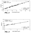
- Figure 4 shows results for samples with approximately 17 percent CaCO 3 , with the remainder of the solids being clay.
- Figure 5 shows results for samples with approximately 33 percent CaCO 3 , with the remainder being clay.
- the linear relationship of the lines through the points shown on the graphs is the basis for the sensor calibration.
- Fig. 3, shows two measurements of a high percentage CaCO 3 sample set taken nearly a month apart. The nearly perfect registration of the two set of points demonstrates excellent long term stability.
Landscapes
- Physics & Mathematics (AREA)
- General Physics & Mathematics (AREA)
- Health & Medical Sciences (AREA)
- General Health & Medical Sciences (AREA)
- Toxicology (AREA)
- Investigating Or Analysing Materials By Optical Means (AREA)
- Coating Apparatus (AREA)
- Paper (AREA)
Applications Claiming Priority (2)
| Application Number | Priority Date | Filing Date | Title |
|---|---|---|---|
| US08/867,524 US5795394A (en) | 1997-06-02 | 1997-06-02 | Coating weight measuring and control apparatus |
| US867524 | 1997-06-02 |
Publications (2)
| Publication Number | Publication Date |
|---|---|
| EP0882945A1 true EP0882945A1 (fr) | 1998-12-09 |
| EP0882945B1 EP0882945B1 (fr) | 2004-10-06 |
Family
ID=25349956
Family Applications (1)
| Application Number | Title | Priority Date | Filing Date |
|---|---|---|---|
| EP98401245A Expired - Lifetime EP0882945B1 (fr) | 1997-06-02 | 1998-05-26 | Appareil de contrôle pour mesurer le poids de revêtements |
Country Status (4)
| Country | Link |
|---|---|
| US (2) | US5795394A (fr) |
| EP (1) | EP0882945B1 (fr) |
| JP (1) | JP4008582B2 (fr) |
| DE (1) | DE69826764T2 (fr) |
Cited By (3)
| Publication number | Priority date | Publication date | Assignee | Title |
|---|---|---|---|---|
| JP2002532700A (ja) * | 1998-12-15 | 2002-10-02 | ハネウエル・メジヤレツクス コーポレーシヨン | ラテックス被覆の厚さを測定し制御する装置 |
| EP1801550A1 (fr) * | 2005-12-20 | 2007-06-27 | Voith Patent GmbH | Procédé pour déterminer le poids d'une couche sur une bande de matériau |
| US7482590B2 (en) | 2006-12-20 | 2009-01-27 | Voith Patent Gmbh | Method for determining the coating quantity on a material web |
Families Citing this family (62)
| Publication number | Priority date | Publication date | Assignee | Title |
|---|---|---|---|---|
| SE507524C2 (sv) * | 1996-10-15 | 1998-06-15 | Stora Kopparbergs Bergslags Ab | Sätt och mätmaskin för analysering av pappersbana |
| DE19803240A1 (de) * | 1998-01-28 | 1999-07-29 | Voith Sulzer Papiertech Patent | Farbvorhang-Auftragsvorrichtung |
| FI108811B (fi) * | 1998-02-12 | 2002-03-28 | Metso Paper Automation Oy | Menetelmä ja laite liikkuvalla alustalla olevan päällysteen määrän mittaamiseksi |
| DE19814490A1 (de) * | 1998-04-01 | 1999-10-07 | Voith Sulzer Papiertech Patent | Verfahren zur Vermeidung oder Beseitigung von Verstopfungen der Austrittsöffnung des Dosierspaltes eines Düsenauftragwerkes |
| FI110638B (fi) * | 1998-10-06 | 2003-02-28 | Metso Paper Automation Oy | Menetelmä ja laite liikkuvalla alustalla olevan silikonipäällysteen määrän mittaamiseksi |
| US6179918B1 (en) * | 1998-11-20 | 2001-01-30 | Honeywell International Inc. | Silicone coat weight measuring and control apparatus |
| US6834824B1 (en) | 1999-03-16 | 2004-12-28 | Black Clawson Converting Machinery, Inc. | Continuous winder and method of winding slit rolls of large diameter on small diameter cores |
| US6290816B1 (en) * | 1999-07-21 | 2001-09-18 | Voith Sulzer Paper Technology North America, Inc. | Paper machine with closed loop control system |
| FI115856B (fi) | 2000-02-10 | 2005-07-29 | Metso Automation Oy | Menetelmä ja laite päällysteen mittaamiseksi |
| WO2001061320A1 (fr) * | 2000-02-15 | 2001-08-23 | Kowalski Craig R | Analyse d'un revetement a plusieurs composants |
| US6672585B2 (en) * | 2000-06-02 | 2004-01-06 | Fuji Photo Film Co., Ltd. | Apparatus for stacking sheet members, apparatus for measuring dimensions of sheet members, and apparatus for and method of marking sheet members |
| US6903339B2 (en) * | 2002-11-26 | 2005-06-07 | The Boeing Company | Method of measuring thickness of an opaque coating using infrared absorbance |
| US6984825B2 (en) * | 2003-02-06 | 2006-01-10 | The Boeing Company | Portable coating weight reader |
| US20050041251A1 (en) * | 2003-08-18 | 2005-02-24 | Hong Cao | Method and apparatus for measuring loading of waterproofing agent in carbon substrate |
| US7075086B2 (en) * | 2003-08-28 | 2006-07-11 | The Boeing Company | Measurement of metal polish quality |
| US20050181118A1 (en) * | 2004-02-12 | 2005-08-18 | Janssen Robert A. | Method for the precision saturation of substrates in preparation for digital printing, and the substrates produced therefrom |
| US7599582B2 (en) * | 2004-11-22 | 2009-10-06 | Honeywell International Inc. | Optical fiber cable take-up mechanism for scanning sensors |
| US20060119840A1 (en) * | 2004-12-08 | 2006-06-08 | Lightwave Energy Systems Co., Inc. | Method for sensing and controlling radiation incident on substrate |
| US7321425B2 (en) * | 2004-12-20 | 2008-01-22 | Honeywell International Inc. | Sensor and methods for measuring select components in sheetmaking systems |
| US7291856B2 (en) * | 2005-04-28 | 2007-11-06 | Honeywell International Inc. | Sensor and methods for measuring select components in moving sheet products |
| JP4615400B2 (ja) * | 2005-09-02 | 2011-01-19 | パナソニック株式会社 | 電池電極板上の多孔質膜の膜測定装置およびそれを用いる塗工装置 |
| JP4955240B2 (ja) * | 2005-09-02 | 2012-06-20 | パナソニック株式会社 | 膜測定装置およびそれを用いる塗工装置 |
| US7859668B2 (en) | 2005-12-15 | 2010-12-28 | Honeywell International Inc. | Apparatus and method for illuminator-independent color measurements |
| US7494567B2 (en) * | 2005-12-15 | 2009-02-24 | Honeywell Asca Inc. | Combined paper sheet temperature and moisture sensor |
| US8017927B2 (en) * | 2005-12-16 | 2011-09-13 | Honeywell International Inc. | Apparatus, system, and method for print quality measurements using multiple adjustable sensors |
| US7573575B2 (en) | 2005-12-29 | 2009-08-11 | Honeywell International Inc. | System and method for color measurements or other spectral measurements of a material |
| US7688447B2 (en) | 2005-12-29 | 2010-03-30 | Honeywell International Inc. | Color sensor |
| US20070227447A1 (en) * | 2006-04-04 | 2007-10-04 | Honeywell International, Inc. | Control of a coating process |
| US7486976B1 (en) | 2006-07-25 | 2009-02-03 | Edward Belotserkovsky | Optical non-invasive blood monitoring system and method |
| US8326390B2 (en) * | 2006-07-25 | 2012-12-04 | Edward Belotserkovsky | Optical non-invasive blood monitoring system and method |
| US7880156B2 (en) * | 2006-12-27 | 2011-02-01 | Honeywell International Inc. | System and method for z-structure measurements using simultaneous multi-band tomography |
| US7592608B2 (en) * | 2008-01-22 | 2009-09-22 | Honeywell International Inc. | Apparatus and method for measuring and/or controlling ultraviolet-activated materials in a paper-making process |
| US8049892B2 (en) * | 2008-01-22 | 2011-11-01 | Honeywell International Inc. | Apparatus and method for camera-based color measurements |
| US8021517B2 (en) * | 2008-02-28 | 2011-09-20 | Honeywell Asca Inc. | Use of fluorescent nanoparticles to make on-line measurements of cross-web and machine-direction component and property variations in paper and continuous web products |
| US7903265B2 (en) * | 2008-04-04 | 2011-03-08 | Toyota Motor Engineering & Manufacturing North America, Inc. | Method for measuring coating uniformity |
| US7858953B2 (en) * | 2008-05-23 | 2010-12-28 | Honeywell Asca Inc. | Use of fluorescent nanoparticles to measure individual layer thicknesses or composition in multi-layer films and to calibrate secondary measurement devices |
| US7800069B2 (en) * | 2008-08-08 | 2010-09-21 | The Boeing Company | Method for performing IR spectroscopy measurements to determine coating weight/amount for metal conversion coatings |
| US7807971B2 (en) * | 2008-11-19 | 2010-10-05 | The Boeing Company | Measurement of moisture in composite materials with near-IR and mid-IR spectroscopy |
| US8394449B2 (en) * | 2008-12-19 | 2013-03-12 | Honeywell Asca Inc. | Differential coat weight measurement by means of nuclear or X-ray gauges |
| US7868296B2 (en) * | 2009-03-30 | 2011-01-11 | Honeywell Asca Inc. | Spectroscopy having correction for broadband distortion for analyzing multi-component samples |
| CN102449428B (zh) * | 2009-05-26 | 2014-07-30 | 乌多·W·布赫 | 涂料样品特征的测量方法和仪器 |
| KR101113504B1 (ko) * | 2009-11-03 | 2012-02-29 | 삼성에스디아이 주식회사 | 전극의 이종 패턴 검출 장치 |
| JP5191511B2 (ja) * | 2010-06-30 | 2013-05-08 | 大王製紙株式会社 | 薬液塗工連続シート中の薬液塗工量を搬送過程で測定する方法、ティシュペーパー製品用二次原反ロールの製造設備及び薬液が塗工されたティシュペーパー製品の製造方法 |
| US8401809B2 (en) | 2010-07-12 | 2013-03-19 | Honeywell International Inc. | System and method for adjusting an on-line appearance sensor system |
| US8314388B2 (en) | 2010-12-20 | 2012-11-20 | Honeywell Asca Inc. | Single-sided infrared sensor for thickness or weight measurement of products containing a reflective layer |
| US8618929B2 (en) | 2011-05-09 | 2013-12-31 | Honeywell International Inc. | Wireless conveyor belt condition monitoring system and related apparatus and method |
| US8975586B2 (en) | 2011-06-06 | 2015-03-10 | Honeywell Asca Inc. | Diffusing measurement window for near and mid IR multichannel sensor |
| US8985051B2 (en) | 2011-12-15 | 2015-03-24 | Honeywell Asca Inc. | Apparatus for producing a spray of changed droplets of aqueous liquid |
| US9201018B2 (en) | 2013-12-23 | 2015-12-01 | Honeywell Asca Inc. | Optimized spatial resolution for a spectroscopic sensor |
| US9927366B2 (en) | 2015-03-24 | 2018-03-27 | Honeywell Limited | Spectroscopic sensor for thickness or weight measurement of thin plastic films |
| US9891164B2 (en) * | 2015-08-27 | 2018-02-13 | Honeywell Limited | Holmium oxide glasses as calibration standards for near infrared moisture sensors |
| US10113973B2 (en) | 2017-01-20 | 2018-10-30 | Microsoft Technology Licensing, Llc | Infrared ink print testing for manufacturing |
| US10157773B1 (en) * | 2017-11-28 | 2018-12-18 | Taiwan Semiconductor Manufacturing Co., Ltd. | Semiconductor structure having layer with re-entrant profile and method of forming the same |
| US11879765B2 (en) * | 2018-09-26 | 2024-01-23 | Honeywell International Inc. | Apparatus for composite sheet weight determinations |
| CA3146533A1 (fr) | 2019-05-31 | 2020-12-03 | Argus Control Systems Ltd. | Appareil et procedes de surveillance de la sante de plante |
| US11333544B2 (en) * | 2019-06-17 | 2022-05-17 | Honeywell International Inc. | Apparatus for simultaneously determining weights of composite sheets |
| US10876882B1 (en) * | 2019-06-26 | 2020-12-29 | Honeywell International Inc. | Online grade selection for weight measurements of composite sheets |
| US11519867B2 (en) | 2019-12-09 | 2022-12-06 | Honeywell International Inc. | X-ray-based determining of weights for coated substrates |
| US11826773B2 (en) | 2021-03-29 | 2023-11-28 | Honeywell International Inc. | Correlate thermographic image data to online scanning basis weight measurement |
| US12597593B2 (en) | 2022-02-07 | 2026-04-07 | Honeywell International Inc. | Manufacturing method for traceability of battery electrodes with fiducial markers |
| US12529660B2 (en) | 2023-05-08 | 2026-01-20 | Honeywell International Inc. | Integrated quality monitoring view for battery manufacturing process |
| EP4575462A1 (fr) * | 2023-12-20 | 2025-06-25 | Flooring Technologies Ltd. | Procédé de détermination de pigment blanc dans une couche de papier |
Citations (4)
| Publication number | Priority date | Publication date | Assignee | Title |
|---|---|---|---|---|
| US4748329A (en) * | 1987-02-17 | 1988-05-31 | Canadian Patents And Development Ltd. | Method for on-line thickness monitoring of a transparent film |
| US4957770A (en) * | 1989-01-27 | 1990-09-18 | Measurex Corporation | Coating weight measuring and control apparatus and method |
| EP0413943A1 (fr) * | 1989-08-14 | 1991-02-27 | Hughes Aircraft Company | Détermination en série et sans contact de l'épaisseur d'une couche de phosphate et composition d'une surface recouverte de phosphate |
| US5338361A (en) * | 1991-11-04 | 1994-08-16 | Measurex Corporation | Multiple coat measurement and control apparatus and method |
Family Cites Families (6)
| Publication number | Priority date | Publication date | Assignee | Title |
|---|---|---|---|---|
| GB8325691D0 (en) * | 1983-09-26 | 1983-10-26 | Wiggins Teape Group Ltd | Measuring water content |
| US4732776A (en) * | 1987-02-24 | 1988-03-22 | Measurex Corporation | Apparatus and method for controlling the thickness of coatings on paper or other materials |
| US4990261A (en) * | 1987-11-19 | 1991-02-05 | Calgon Corporation | Method for monitoring and/or controlling liquid-solid separation processes |
| US5104485A (en) * | 1988-05-31 | 1992-04-14 | Hercules Incorporated | Method of measuring non-aqueous constituents in a pulp slurry of a water/cellulose matrix |
| US4921574A (en) * | 1989-01-27 | 1990-05-01 | Measurex Corporation | Process for controlling properties of travelling sheets with scan widths less than the sheet width |
| US5492601A (en) * | 1994-07-29 | 1996-02-20 | Wangner Systems Corporation | Laser apparatus and method for monitoring the de-watering of stock on papermaking machines |
-
1997
- 1997-06-02 US US08/867,524 patent/US5795394A/en not_active Expired - Lifetime
-
1998
- 1998-03-26 US US09/048,006 patent/US6074483A/en not_active Expired - Lifetime
- 1998-05-26 DE DE69826764T patent/DE69826764T2/de not_active Expired - Lifetime
- 1998-05-26 EP EP98401245A patent/EP0882945B1/fr not_active Expired - Lifetime
- 1998-06-02 JP JP19093698A patent/JP4008582B2/ja not_active Expired - Lifetime
Patent Citations (4)
| Publication number | Priority date | Publication date | Assignee | Title |
|---|---|---|---|---|
| US4748329A (en) * | 1987-02-17 | 1988-05-31 | Canadian Patents And Development Ltd. | Method for on-line thickness monitoring of a transparent film |
| US4957770A (en) * | 1989-01-27 | 1990-09-18 | Measurex Corporation | Coating weight measuring and control apparatus and method |
| EP0413943A1 (fr) * | 1989-08-14 | 1991-02-27 | Hughes Aircraft Company | Détermination en série et sans contact de l'épaisseur d'une couche de phosphate et composition d'une surface recouverte de phosphate |
| US5338361A (en) * | 1991-11-04 | 1994-08-16 | Measurex Corporation | Multiple coat measurement and control apparatus and method |
Cited By (3)
| Publication number | Priority date | Publication date | Assignee | Title |
|---|---|---|---|---|
| JP2002532700A (ja) * | 1998-12-15 | 2002-10-02 | ハネウエル・メジヤレツクス コーポレーシヨン | ラテックス被覆の厚さを測定し制御する装置 |
| EP1801550A1 (fr) * | 2005-12-20 | 2007-06-27 | Voith Patent GmbH | Procédé pour déterminer le poids d'une couche sur une bande de matériau |
| US7482590B2 (en) | 2006-12-20 | 2009-01-27 | Voith Patent Gmbh | Method for determining the coating quantity on a material web |
Also Published As
| Publication number | Publication date |
|---|---|
| JPH11230819A (ja) | 1999-08-27 |
| EP0882945B1 (fr) | 2004-10-06 |
| DE69826764D1 (de) | 2004-11-11 |
| DE69826764T2 (de) | 2005-10-27 |
| JP4008582B2 (ja) | 2007-11-14 |
| US6074483A (en) | 2000-06-13 |
| US5795394A (en) | 1998-08-18 |
Similar Documents
| Publication | Publication Date | Title |
|---|---|---|
| EP0882945B1 (fr) | Appareil de contrôle pour mesurer le poids de revêtements | |
| EP0611329B1 (fr) | Regulation et mesure de revetements multiples | |
| US4957770A (en) | Coating weight measuring and control apparatus and method | |
| CA2351866C (fr) | Dispositif de mesure et de reglage de l'epaisseur d'une couche de silicone | |
| EP1149269B1 (fr) | Appareil de controle et de mesure de l'epaisseur d'un revetement de latex | |
| US5014288A (en) | X-ray coating weight controller and sensor | |
| EP0256742B1 (fr) | Procédé pour mesurer la concentration d'un adhésif d'une couche de revêtement de surface | |
| FI108811B (fi) | Menetelmä ja laite liikkuvalla alustalla olevan päällysteen määrän mittaamiseksi | |
| US5296257A (en) | Process for two-sided coating of a web | |
| CA2279904C (fr) | Procede de determination des composants d'une couche sur un materiau de base mobile | |
| US7482590B2 (en) | Method for determining the coating quantity on a material web |
Legal Events
| Date | Code | Title | Description |
|---|---|---|---|
| PUAI | Public reference made under article 153(3) epc to a published international application that has entered the european phase |
Free format text: ORIGINAL CODE: 0009012 |
|
| AK | Designated contracting states |
Kind code of ref document: A1 Designated state(s): CH DE FI GB IT LI SE |
|
| AX | Request for extension of the european patent |
Free format text: AL;LT;LV;MK;RO;SI |
|
| 17P | Request for examination filed |
Effective date: 19990417 |
|
| AKX | Designation fees paid |
Free format text: CH DE FI GB IT LI SE |
|
| 17Q | First examination report despatched |
Effective date: 20020930 |
|
| GRAP | Despatch of communication of intention to grant a patent |
Free format text: ORIGINAL CODE: EPIDOSNIGR1 |
|
| RTI1 | Title (correction) |
Free format text: COATING WEIGHT MEASURING AND CONTROL APPARATUS |
|
| RTI1 | Title (correction) |
Free format text: COATING WEIGHT MEASURING AND CONTROL APPARATUS |
|
| GRAS | Grant fee paid |
Free format text: ORIGINAL CODE: EPIDOSNIGR3 |
|
| GRAA | (expected) grant |
Free format text: ORIGINAL CODE: 0009210 |
|
| AK | Designated contracting states |
Kind code of ref document: B1 Designated state(s): CH DE FI GB IT LI SE |
|
| PG25 | Lapsed in a contracting state [announced via postgrant information from national office to epo] |
Ref country code: LI Free format text: LAPSE BECAUSE OF FAILURE TO SUBMIT A TRANSLATION OF THE DESCRIPTION OR TO PAY THE FEE WITHIN THE PRESCRIBED TIME-LIMIT Effective date: 20041006 Ref country code: IT Free format text: LAPSE BECAUSE OF FAILURE TO SUBMIT A TRANSLATION OF THE DESCRIPTION OR TO PAY THE FEE WITHIN THE PRESCRIBED TIME-LIMIT;WARNING: LAPSES OF ITALIAN PATENTS WITH EFFECTIVE DATE BEFORE 2007 MAY HAVE OCCURRED AT ANY TIME BEFORE 2007. THE CORRECT EFFECTIVE DATE MAY BE DIFFERENT FROM THE ONE RECORDED. Effective date: 20041006 Ref country code: CH Free format text: LAPSE BECAUSE OF FAILURE TO SUBMIT A TRANSLATION OF THE DESCRIPTION OR TO PAY THE FEE WITHIN THE PRESCRIBED TIME-LIMIT Effective date: 20041006 |
|
| REG | Reference to a national code |
Ref country code: GB Ref legal event code: FG4D |
|
| REG | Reference to a national code |
Ref country code: CH Ref legal event code: EP |
|
| REF | Corresponds to: |
Ref document number: 69826764 Country of ref document: DE Date of ref document: 20041111 Kind code of ref document: P |
|
| REG | Reference to a national code |
Ref country code: SE Ref legal event code: TRGR |
|
| REG | Reference to a national code |
Ref country code: CH Ref legal event code: PL |
|
| PLBE | No opposition filed within time limit |
Free format text: ORIGINAL CODE: 0009261 |
|
| STAA | Information on the status of an ep patent application or granted ep patent |
Free format text: STATUS: NO OPPOSITION FILED WITHIN TIME LIMIT |
|
| 26N | No opposition filed |
Effective date: 20050707 |
|
| PGFP | Annual fee paid to national office [announced via postgrant information from national office to epo] |
Ref country code: SE Payment date: 20130507 Year of fee payment: 16 |
|
| PGFP | Annual fee paid to national office [announced via postgrant information from national office to epo] |
Ref country code: GB Payment date: 20140425 Year of fee payment: 17 |
|
| PGFP | Annual fee paid to national office [announced via postgrant information from national office to epo] |
Ref country code: DE Payment date: 20140602 Year of fee payment: 17 |
|
| PG25 | Lapsed in a contracting state [announced via postgrant information from national office to epo] |
Ref country code: SE Free format text: LAPSE BECAUSE OF NON-PAYMENT OF DUE FEES Effective date: 20140527 |
|
| REG | Reference to a national code |
Ref country code: SE Ref legal event code: EUG |
|
| REG | Reference to a national code |
Ref country code: DE Ref legal event code: R119 Ref document number: 69826764 Country of ref document: DE |
|
| GBPC | Gb: european patent ceased through non-payment of renewal fee |
Effective date: 20150526 |
|
| PG25 | Lapsed in a contracting state [announced via postgrant information from national office to epo] |
Ref country code: GB Free format text: LAPSE BECAUSE OF NON-PAYMENT OF DUE FEES Effective date: 20150526 Ref country code: DE Free format text: LAPSE BECAUSE OF NON-PAYMENT OF DUE FEES Effective date: 20151201 |
|
| PGFP | Annual fee paid to national office [announced via postgrant information from national office to epo] |
Ref country code: FI Payment date: 20160509 Year of fee payment: 19 |
|
| PG25 | Lapsed in a contracting state [announced via postgrant information from national office to epo] |
Ref country code: FI Free format text: LAPSE BECAUSE OF NON-PAYMENT OF DUE FEES Effective date: 20170526 |