EP0883190A2 - Strukturierte organische Schichten in einem vollfarben organischen elektrolumeszierenden Anzeigevorrichtung auf einem Dünnschichttransistoranordnungssubstrat - Google Patents
Strukturierte organische Schichten in einem vollfarben organischen elektrolumeszierenden Anzeigevorrichtung auf einem Dünnschichttransistoranordnungssubstrat Download PDFInfo
- Publication number
- EP0883190A2 EP0883190A2 EP98201741A EP98201741A EP0883190A2 EP 0883190 A2 EP0883190 A2 EP 0883190A2 EP 98201741 A EP98201741 A EP 98201741A EP 98201741 A EP98201741 A EP 98201741A EP 0883190 A2 EP0883190 A2 EP 0883190A2
- Authority
- EP
- European Patent Office
- Prior art keywords
- organic
- color
- substrate
- subpixels
- medium
- Prior art date
- Legal status (The legal status is an assumption and is not a legal conclusion. Google has not performed a legal analysis and makes no representation as to the accuracy of the status listed.)
- Withdrawn
Links
Images


Classifications
-
- C—CHEMISTRY; METALLURGY
- C23—COATING METALLIC MATERIAL; COATING MATERIAL WITH METALLIC MATERIAL; CHEMICAL SURFACE TREATMENT; DIFFUSION TREATMENT OF METALLIC MATERIAL; COATING BY VACUUM EVAPORATION, BY SPUTTERING, BY ION IMPLANTATION OR BY CHEMICAL VAPOUR DEPOSITION, IN GENERAL; INHIBITING CORROSION OF METALLIC MATERIAL OR INCRUSTATION IN GENERAL
- C23C—COATING METALLIC MATERIAL; COATING MATERIAL WITH METALLIC MATERIAL; SURFACE TREATMENT OF METALLIC MATERIAL BY DIFFUSION INTO THE SURFACE, BY CHEMICAL CONVERSION OR SUBSTITUTION; COATING BY VACUUM EVAPORATION, BY SPUTTERING, BY ION IMPLANTATION OR BY CHEMICAL VAPOUR DEPOSITION, IN GENERAL
- C23C14/00—Coating by vacuum evaporation, by sputtering or by ion implantation of the coating forming material
- C23C14/04—Coating on selected surface areas, e.g. using masks
- C23C14/048—Coating on selected surface areas, e.g. using masks using irradiation by energy or particles
-
- H—ELECTRICITY
- H10—SEMICONDUCTOR DEVICES; ELECTRIC SOLID-STATE DEVICES NOT OTHERWISE PROVIDED FOR
- H10K—ORGANIC ELECTRIC SOLID-STATE DEVICES
- H10K59/00—Integrated devices, or assemblies of multiple devices, comprising at least one organic light-emitting element covered by group H10K50/00
- H10K59/30—Devices specially adapted for multicolour light emission
- H10K59/35—Devices specially adapted for multicolour light emission comprising red-green-blue [RGB] subpixels
-
- H—ELECTRICITY
- H10—SEMICONDUCTOR DEVICES; ELECTRIC SOLID-STATE DEVICES NOT OTHERWISE PROVIDED FOR
- H10K—ORGANIC ELECTRIC SOLID-STATE DEVICES
- H10K71/00—Manufacture or treatment specially adapted for the organic devices covered by this subclass
-
- H—ELECTRICITY
- H10—SEMICONDUCTOR DEVICES; ELECTRIC SOLID-STATE DEVICES NOT OTHERWISE PROVIDED FOR
- H10K—ORGANIC ELECTRIC SOLID-STATE DEVICES
- H10K71/00—Manufacture or treatment specially adapted for the organic devices covered by this subclass
- H10K71/10—Deposition of organic active material
- H10K71/16—Deposition of organic active material using physical vapour deposition [PVD], e.g. vacuum deposition or sputtering
- H10K71/166—Deposition of organic active material using physical vapour deposition [PVD], e.g. vacuum deposition or sputtering using selective deposition, e.g. using a mask
-
- H—ELECTRICITY
- H10—SEMICONDUCTOR DEVICES; ELECTRIC SOLID-STATE DEVICES NOT OTHERWISE PROVIDED FOR
- H10K—ORGANIC ELECTRIC SOLID-STATE DEVICES
- H10K71/00—Manufacture or treatment specially adapted for the organic devices covered by this subclass
- H10K71/10—Deposition of organic active material
- H10K71/18—Deposition of organic active material using non-liquid printing techniques, e.g. thermal transfer printing from a donor sheet
Definitions
- the present invention relates to methods of forming patterned organic layers in a full-color electroluminescent (EL) organic display array on a substrate comprised of a two-dimensional thin film transistor (TFT) active matrix array of pixels and subpixels.
- EL electroluminescent
- TFT thin film transistor
- Each pixel has raised surface portions and a recessed surface portion which also reveals the transparent anode bottom electrode.
- the deposition of a single-color forming conformal EL layer over the entire surface area of each of the pixels is advantageous from the viewpoint of simplicity of manufacturing, since such a single-color forming EL layer does not have to be patterned.
- each pixel of a EL display into three color subpixels capable of generating red, green, or blue light.
- the present invention provides such methods of patterning, taking advantage of the TFTs topological surface features to form a full-color organic EL display.
- this object is achieved by a method of forming a full-color organic electroluminescent (EL) display, comprising:
- Major advantages of the method of the invention are formation of high definition organic EL layers with each of the red, green, or blue color forming layers being deposited into recessed surface portions of designated subpixels, from EL donor coatings; excellent utilization of the organic EL materials; excellent uniformity of the deposited layers over a large TFT substrate area; and precise control of the thickness of each layer formed in the designated subpixels.
- the Arm "display” or “display panel” is employed to designate a screen capable of electronically displaying video images or text.
- pixel is employed in its art recognized usage to designate an area of a display panel that can be stimulated to emit light independently of other areas.
- multicolor is employed to describe a display panel that is capable of emitting light of a different hue in different areas. In particular, it is employed to describe a display panel that is capable of displaying images of different colors. These areas are not necessarily contiguous.
- full-color is employed to describe multicolor display panels that are capable of emitting in the red, green, and blue regions of the visible spectrum and displaying images in any combination of hues.
- the red, green, and blue colors constitute the three primary colors from which all other colors can be generated by appropriately mixing these three primaries.
- the term "hue” refers to the intensity profile of light emission within the visible spectrum, with different hues exhibiting visually discernible differences in color.
- the pixel or subpixel is generally used to designate the smallest addressable unit in a display panel. For a monochrome display, there is no distinction between pixel or subpixels.
- subpixel is used in multicolor display panel and is employed to designate any portion of a pixel which can be independently addressable to emit a specific color. For example, a blue subpixel is that portion of a pixel which can be addressed to emit blue light.
- a pixel In a full-color display, a pixel generally comprises of three primary color subpixels, namely, blue, green, and red.
- the term "pitch" is used to designate the distance separating two pixels or subpixels in a display panel. Thus, a subpixel pitch means the separation between two subpixels.
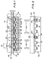
- FIG. 1 there is shown one preferred arrangement for the practice of the method in accordance with the present invention.
- a TFT active matrix array substrate 20 Arranged within a reduced pressure chamber 121 having a pump port 122 is a TFT active matrix array substrate 20 depicted schematically in cross-sectional view as representing, for example, the major raised and recessed surface portions of a TFT pixel shown in FIG. 9 of the above cited US-A-5,550,066.
- such a pixel is comprised of an insulating transparent substrate 41 and a plurality of layers deposited thereon. Among these layers are two TFTs 44 and 48, an insulating layer 52, an upper electrode 62, a transparent anode bottom electrode 72, and a passivating layer 74.
- This multilayer construction of each pixel or subpixel of the TFT active matrix array substrate 20 results in raised surface portions 92 of each subpixel (only one most highly raised portion is depicted in the drawings to provide clarity of presentation) and a recessed surface portion 94 which reveals the bottom electrode 72.
- An aperture mask 112 is positioned on, or in close proximity to, the raised surface portions 92 of the pixels or subpixels 90 on the TFT substrate 20 in an oriented relationship between the apertures 113 and the designated recessed surface portions 94 of the substrate 20.
- the oriented relationship between the apertures 113 of the aperture mask 112 and the designated recessed surface portions 94 can he more readily visualized in conjunction with FIG. 3, where orientation marks 152 (also referred to as alignment targets) are shown which are used to orient the aperture mask 112 with respect to matching orientation marks (not shown) on the TFT substrate 20.
- the aperture mask 112 is oriented with respect to the TFT substrate such that the apertures 113 are positioned in a first-color (for example, a red organic EL medium) mask position over the designated color subpixel portions 94 on the substrate.
- a first-color for example, a red organic EL medium
- the subpixels 90 are arranged in rows and orthogonal columns, and the 113 on the aperture mask 112 are similarly arranged in rows and columns, as indicated by the coordinates x and y in FIG. 3, whereby a subpixel pitch in both the x and y directions indicates the distance between subpixels.
- a ratio between a subpixel pitch in one direction and in an orthogonal second direction can have a value ranging from 1 to 3.
- the aperture mask 112 is repositioned on the rased surface portions 92 of the TFT active matrix array substrate 20 in an oriented relationship between the apertures 113 and corresponding designated recessed surface portions 94 such that in a second-color (for example, a green organic EL medium) mask position a second-color (e.g., green) organic EL layer can be deposited into designated recessed electrodes of the green subpixels.
- a second-color for example, a green organic EL medium
- a second-color (e.g., green) organic EL layer can be deposited into designated recessed electrodes of the green subpixels.
- repositioning the apes 113 into a third-color (for example, a blue organic EL medium) mask position permits deposition of a third-color (e.g., blue) organic EL layer into designated blue recessed surface portions of the TFT array subpixels.
- a third-color for example, a blue organic EL medium
- the plurality of apertures 113 are depicted in a solid outline corresponding to a first-color (e.g., red) mask position, in a dashed outline corresponding to a second-color (e.g., green) mask position, and in a dotted outline corresponding to a third-color (e.g., blue) mask position over the corresponding recessed surface portions of the subpixels 90 in accordance with a selected desired color pattern to be achieved in the full-color EL display array, shown here for illustrative purposes as a diagonal color pattern.
- a first-color e.g., red
- a second-color e.g., green
- a third-color e.g., blue
- a donor support 124 having a coating 123 on a surface facing the aperture mask 112 is spaced from the aperture mask by a distance D, which is intended to indicate a distance which ensures a position of a transferable relationship between the coating 123 on the support 124 and the aperture mask 112 with the plurality of apertures 113.
- the coating 123 is designated as donor coating containing an organic EL medium of a specific color.
- a plurality of heating elements 125 is arranged to heat the donor support 124 in a reduced pressure environment to a temperature at which the EL organic material of the donor coating 123 vaporizes as schematically indicated by the dotted vapor arrows 123v, thereby forming a deposited electroluminescent organic layer 123d over the aperture mask 112 and in the designated recessed surface portion 94 of the TFT substrate subpixels 90 through the respective plurality of apertures 113 of the aperture mask 112.
- the donor support 124 with donor coating 123 thereupon enters and leaves the chamber 121 through suitably designed ports (not shown).
- the aperture mask 112 is repositioned with resect to the substrate and translated from a first-color mask position to a second- or third-color mask position through a precise mechanical position aligner (not shown).
- the aperture mask is held in contact or close proximity to the substrate, where close proximity is a spacing of less than 250 micrometers between the aperture mask and the raised surface portions 92 of the subpixels.
- the chamber 121 Prior to actuating the heating elements 125, the chamber 121 is preferably provided with an environment of reduced pressure.
- the environment of reduced pressure is preferably at a pressure value of less than 1 Torr during the heating step so that the organic material transferred from the donor support forms a uniform layer in the designated recessed surface portions 94 of the subpixels 90 of the TFT substrate 20.
- the donor support 124 is first prepared by providing a transferable coating of an organic EL donor medium thereon by a suitable process forming the donor coating 123.
- suitable methods for coating the support include solution coating, meniscus coating, dip coating, spraying, screen printing, and vapor deposition coating in a vacuum chamber. These methods are specifically designed to produce a uniform coating of precise thickness on a donor support which may be a sheet, a rigid support such as glass, a foil, or a flexible web. Using any of these methods, a support coated with a predetermined thickness of the desired transferable EL organic donor medium can be readily prepared in large quantity.
- a preferred method for the preparation of a flexible donor support, such as for example, a donor web is the roll-to-roll vacuum coating because the coating thickness and uniformity on the support can be precisely controlled with an accuracy of better than a few percent.
- the donor support 124 can be made of any of several materials which meet at least the following requirements.
- the donor support must be capable of maintaining the structural integrity during the heat-induced transfer step. Additionally, the donor support must be capable of receiving on one surface a relatively thin coating of EL organic donor medium, and of retaining this coating without degradation during anticipated storage periods of the coated support Support materials meeting these requirements include, for example, metal foils, certain plastic foils with a high glass transition temperature such as Kapton®. While selection of suitable support materials can rely on known engineering approaches, it will be appreciated that certain aspects of a selected support material merit further consideration when configured as a donor support useful in the practice of the invention. For example, the support may require a multi-step cleaning and surface preparation process prior to precoating with a transferable EL organic medium.
- the support material is a radiation transmissive material
- the incorporation of a radiation-absorptive material on the donor support 124 may be advantageous in enhancing the heat absorption and thus the transfer of donor coating 123 from the donor support 124 to the recessed surface portions 94 of the TFT substrate 20.
- the transfer of the EL organic donor medium 123 from the donor support 124 into the recessed surface portions 94 of the TFT substrate 20 can also be caused by translating or scanning a heat source or a light source in proximity to and along the support surface to be heated. While a scanning heat source may increase the total time to form a layer in the designated recessed surface portions 94 of the subpixels 90, a scanning heat source may advantageously reduce excessive heating of the substrate surface and any attendant undesirable crystallization or aggregation of the layer 123d being formed in the subpixel recesses of the substrate.
- the aperture mask 112 is conveniently fabricated from a metallic foil or sheet by micromachining methods well known in this art. Such micromachining methods are capable of rendering the plurality of apertures 113 which can be as small as a few micrometers in dimension and, if the aperture mask 112 is to contain a plurality of closely spaced apertures, the distance between adjacent apertures can also be as small as a few micrometers.
- the orientation marks 152 (see FIG. 3) of the aperture mask 112 can be apertures through which a directed beam of a light can pass, or they can be opaque in appearance. In any event, the orientation marks 152 on the aperture mask 112 are used to position the aperture mask in an oriented relationship with the TFT substrate 20 which has spatially matching or coincident sets of orientation marks (not shown).
- Aperture masks defining a particular selected color pattern of apertures are advantageously used in the practice of the invention to form full-color organic EL layers in designated recessed surface portions of pixels in correspondence with the selected particular color pattern.
- the organic EL media used in the method of forming organic layers in accordance with this invention can take any of the forms, such as those disclosed in the following commonly assigned Tang US-A-4,356,429; VanSlyke et al US-A-4,539,507; VanSlyke et al US-A-4,720,432; Tang et al US-A-4,885,211; Tang et al US-A-4,769,292; Littman et al US-A-5,059,861; VanSlyke US-A-5,047,687; VanSlyke et al US-A-5,059,862; VanSlyke et al US-A-5,061,617; and Tang et al US-A-5,294,870; the disclosures of which are here incorporated by reference.
- an efficient EL layer is formed on the bottom electrodes 72 by sequentially depositing a hole injecting layer, a hole transporting layer, a luminescent layer, and an electron injecting layer.
- organic materials can be useful to form these organic EL layers on the recessed surface portions of the substrate in accordance with the present invention.
- Selection of particular organic EL media is influenced, among other considerations, by their ability to provide uniform transferable donor coatings on a donor support, and by their ability to maintain transferable properties during a storage interval between preparation of a coating on the donor support and its deployment in the heat transfer step.
- the light emitting properties of each of the layers are tailored to provide light emission over specific spectral regions of the visible spectrum by incorporating into the donor coating 123 and thereby into the deposited layers 123d a combination of an electroluminescent organic host material and at least one highly fluorescent organic material.
- a different transferable organic EL coating is precoated on a donor support for each of the primary colors (red, green, and blue) to be obtained in a full-color organic EL display.
- the organic EL host material is combined with a highly fluorescent organic dye tailored to emit red light when such a red light emitting subpixel of a multicolor organic EL display is actuated by at least one of the TFTs 44, 48 corresponding to that particular subpixel.
- a donor coating 123 is prepared by suitably combining an organic EL host material with a green light emitting highly fluorescent dye.
- recessed surface portions 94 of subpixels 90 are to receive a blue light emitting EL medium
- a donor coating consisting of a combination of a organic EL material and a blue light emitting highly fluorescent dye is prepared on the donor support.
- the hole injecting layer, the hole transport layer, and the electron transport layer, which together perform the charge transport functions, do not require patterning, and therefore can be deposited by a conventional vapor deposition method.
- FIG. 2 there is shown a simplified rendition of a TFT active matrix array substrate 20 identical to the substrate described with reference to FIG. 1.
- Like numeral designations denote like parts or functions.
- the method of forming patterned organic layers in a full-color EL display on the two-dimensional TFT substrate is distinct over the method previously described with reference to FIG. 1, in that the transferable coating 123 of a color forming EL donor material is precoated on one surface of an optical mask which is comprised of a pattern of absorbers 126.
- the patterned absorbers are formed on a heat transmissive or on a light transmissive optical mask support 129, through which radiation (heat, light) 130 is incident.
- the incident radiation 130 is preferentially absorbed by the patterned heat absorbers 126, thereby causing the EL medium in coating 123 to be selectively heated and thus transferred as a vapor 123v from the optical mask to the bottom electrodes 72 of the designated color EL subpixels and thus depositing the red, green, or blue color EL subpixels designated at 123d.
- the patterned absorbers 126 When the incident radiation 130 is from a heat source, the patterned absorbers 126 function as heat absorbers. When the incident radiation 130 is from a light source, the patterned absorbers 126 are light absorbers.
- the transferable coating 123 on the optical mask is held in contact or close proximity to the substrate during the vapor deposition transfer step. Close proximity is a spacing of less than 250 micrometers between the coating 123 and the raised surface portions 92 of the subpixels.
- the method of FIG. 2 of forming a full-color organic EL display on a TFT substrate is preferably practiced in an environment of reduced pressure during the pattern-selective transfer and deposition of the EL medium for each of the color EL subpixels.
- the reduced pressure chamber 121 of FIG. 1 is not shown in FIG. 2.
- the optical mask support 129 can be of any material which is transmissive to the incident radiation 130 and which provides structural integrity under the conditions of use of the optical mask. Glass, quartz, and sapphire are examples of suitable optical mask support materials.
- the pattern of absorbers 126 can, in principle, be made from any material which is capable of preferentially absorbing radiation (heat or light) with respect to the mask support 123.
- the optical mask should be reusable and, accordingly, should be readily cleanable prior to recoating with a transferable coating of a color forming EL donor material;
- the patterned absorbers should be highly adherent to the aforementioned mask support materials, and remain highly adherent under the conditions of exposure to high temperature during repeated use of the optical mask.
- examples of preferred materials for forming the pattern of absorbers include patterns of carbon, thin metal layer such as chromium, metal/semiconductor alloyed layers such as chromium/germanium multilayers, and a material known in the art as "black chrome.”
- the incident radiation can be from a pulsed light where the pulse width can range from tens of milliseconds to nanoseconds.
- focused scanning light sources can be used advantageously in the practice of the methods, including laser sources.
- the light source is focused onto a small area (e.g., 1 mm x 1 mm) and is swept across the surface of the optical mask. In the scan mode, the light source can either be continuous or pulsed.
- FIG. 4 there is shown a schematic side view of another optical mask method useful for depositing a color forming EL layer into designated subpixels of a TFT substrate
- the optical mask of FIG. 4 is distinct over the optical mask of FIG. 2 in that a heat insulating layer 128 is shown as uniformly covering the surface adjacent to the substrate 20 of a radiation transmissive optical mask support 129.
- absorbers 126 On the surface of the heat insulating layer 128 are disposed absorbers 126 which constitute a subpixel pattern for one of the color forming EL media.
- a transferable coating 123 of a color forming EL donor material is provided over the heat insulating layer 128 and over the patterned absorbers 126.
- the transferable coating 123 on the optical mask is held in contact or close proximity to the substrate during the vapor deposition transfer step, as described above with reference to FIG. 2.
- the heat insulating layer minimizes heat loss to the optical mask support 129 from the heat absorbers 126, thereby enhancing vapor deposition of the EL layers via vapor paths 123v at a given level of incident radiation (heat or light radiation) as indicated by the arrows 130.
- suitable heat insulating layers 128 include high temperature polymers, for example, polycarbonate, polyimide, and photocrosslinkable resins, low density silica gels, and, in general, any nonabsorbing material of a lower thermal capacity than that of the mask support 129.
- the heat insulating layer is subject to the same aforementioned considerations of physical integrity as are the optical mask support 129 and the absorbers 126.
- FIG. 5 there is depicted a schematic side view of another optical mask method useful for vapor depositing a color forming organic EL layer into designated subpixels of a TFT substrate.
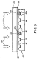
- the optical mask of FIG. 5 has, on the surface of the mask support 129 adjacent to the TFT substrate 20, not only a pattern of absorbers 126, but reflectors 127 disposed on that surface. The reflectors 127 cover the area of the mask support surface between the absorbers 126.
- a donor coating 123 of a color forming organic EL medium is formed over the absorbers 126 and over the reflectors 127.
- the transferable coating 123 on the optical mask is held in contact or close proximity to the substrate during the vapor deposition transfer step, as described above with reference to FIG. 2.
- the reflectors 127 reflect the radiation 130 incident thereon through the radiation transmissive mask support 129, thereby minimizing a temperature increase of the donor EL coating 123 in all coating regions except for the regions defined by the pattern of absorbers 126.
- the reflectors 127 are preferably made from a thin film of a reflective metal such as, for example, a thin film of reflective chromium, referred to in the art also as "bright chrome,” which is known to be highly adherent to the aforementioned optical mask support materials, and to be abrasion resistant.
- a reflective metal such as, for example, a thin film of reflective chromium, referred to in the art also as "bright chrome,” which is known to be highly adherent to the aforementioned optical mask support materials, and to be abrasion resistant.
- the optical mask method of forming a full-color organic EL display depicted in FIG. 5 is preferably practiced in an environment of reduced pressure during the deposition of the EL medium for each of the color EL subpixels.
- FIG. 6 there is shown another optical mask method of vapor depositing a color forming organic EL layer into designated subpixels of a TFT substrate.
- the optical mask has, on a surface adjacent to the TFT substrate 20 of the radiation transmissive mask support 129, in sequence, a heat insulating layer 128, a pattern of absorbers 126 with reflectors 127 therebetween, and a donor coating 123 of a color forming organic EL medium.
- providing a TFT substrate includes selecting a polysilicon TFT array on a quartz substrate, a polysilicon TFT array on a glass substrate, an amorphous silicon TFT array on a glass substrate, or a TFT array on a crystalline silicon substrate.
- the present invention anticipates providing an organic EL display array on a TFT substrate in which the top electrode 84 is a transparent conductor. Alternatively, for other applications, it is desirable to furnish the bottom electrode 72 as the transparent conductor in a TFT substrate.
Landscapes
- Engineering & Computer Science (AREA)
- Chemical & Material Sciences (AREA)
- Manufacturing & Machinery (AREA)
- Health & Medical Sciences (AREA)
- Toxicology (AREA)
- Chemical Kinetics & Catalysis (AREA)
- Materials Engineering (AREA)
- Mechanical Engineering (AREA)
- Metallurgy (AREA)
- Organic Chemistry (AREA)
- Electroluminescent Light Sources (AREA)
Applications Claiming Priority (2)
| Application Number | Priority Date | Filing Date | Title |
|---|---|---|---|
| US08/870,475 US5937272A (en) | 1997-06-06 | 1997-06-06 | Patterned organic layers in a full-color organic electroluminescent display array on a thin film transistor array substrate |
| US870475 | 1997-06-06 |
Publications (2)
| Publication Number | Publication Date |
|---|---|
| EP0883190A2 true EP0883190A2 (de) | 1998-12-09 |
| EP0883190A3 EP0883190A3 (de) | 2004-03-10 |
Family
ID=25355460
Family Applications (1)
| Application Number | Title | Priority Date | Filing Date |
|---|---|---|---|
| EP19980201741 Withdrawn EP0883190A3 (de) | 1997-06-06 | 1998-05-25 | Strukturierte organische Schichten in einem vollfarben organischen elektrolumeszierenden Anzeigevorrichtung auf einem Dünnschichttransistoranordnungssubstrat |
Country Status (3)
| Country | Link |
|---|---|
| US (1) | US5937272A (de) |
| EP (1) | EP0883190A3 (de) |
| JP (1) | JPH1154275A (de) |
Cited By (26)
| Publication number | Priority date | Publication date | Assignee | Title |
|---|---|---|---|---|
| WO2000060669A1 (en) * | 1999-04-07 | 2000-10-12 | Microemissive Displays Limited | An optoelectronic display |
| EP1321303A1 (de) * | 2001-12-12 | 2003-06-25 | Eastman Kodak Company | Vorrichtung zum Übertragen von organischem Material von einem Donor, um eine Schicht in einer OLED zu bilden |
| EP1274130A3 (de) * | 2001-07-03 | 2004-01-28 | Lg Electronics Inc. | Organische elektrolumineszente Anzeigevorrichtung und Herstellungsverfahren |
| EP1102317A3 (de) * | 1999-11-19 | 2004-03-24 | Sony Corporation | Organische EL Anzeigevorrichtung und Herstellungsverfahren |
| WO2005011015A1 (en) * | 2003-07-16 | 2005-02-03 | Eastman Kodak Company | Improving the aperture ratio of an oled |
| US6939732B2 (en) * | 2001-07-11 | 2005-09-06 | Osram Opto Semiconductors Gmbh | Organic, colored, electroluminescent display and the production thereof |
| WO2005093814A1 (en) * | 2004-03-02 | 2005-10-06 | Eastman Kodak Company | Oled donor sheet having rigid edge frame |
| EP1321988A3 (de) * | 2001-12-19 | 2005-10-12 | Eastman Kodak Company | Methode zur Übertragung von organischem Material von einem Träger auf eine organische Leuchtdiode |
| EP1107331A3 (de) * | 1999-12-09 | 2005-11-02 | Daicel Chemical Industries, Ltd. | Material für organische elektrolumineszente Vorrichtung und Herstellungsverfahren |
| EP1408564A3 (de) * | 2002-10-08 | 2006-01-11 | Eastman Kodak Company | Abstandskontrolle während des laserunterstützten Thermotransfers bei der OLED-Herstellung |
| EP1630884A1 (de) * | 2004-08-30 | 2006-03-01 | Samsung SDI Co., Ltd. | Laserinduziertes thermisches Abscheidungsverfahren und Verfahren zur Herstellung einer organischen Elektrolumineszenzanzeige |
| EP1650046A1 (de) * | 2004-10-19 | 2006-04-26 | Samsung SDI Co., Ltd. | Donorsubstrat und Prozess mit deren Verwendung zum Herstellung einer organischen elektrolumineszenten Anzeigevorrichtung |
| EP1469534A3 (de) * | 2003-04-16 | 2006-05-10 | Eastman Kodak Company | Verfahren zur Herstellung einer emittierenden Schicht mit verbesserter Stabilität in einer OLED-Vorrichtung von einem Donorelement |
| EP1246273A3 (de) * | 2001-03-27 | 2006-10-18 | SANYO ELECTRIC Co., Ltd. | Elektrolumineszente Anzeige und Herstellungsverfahren, Maske und Herstellungsverfahren |
| EP1394872A3 (de) * | 2002-08-29 | 2009-04-01 | Eastman Kodak Company | Verwendung von Justiermarken auf ein Substrat für das Übertragen mittels Laser Transfer von organischem Material von einem Donator auf das Substrat |
| US7526858B2 (en) | 2002-04-25 | 2009-05-05 | Seiko Epson Corporation | Apparatus for making electronic devices |
| EP1324404A3 (de) * | 2001-12-27 | 2009-06-10 | Eastman Kodak Company | In-situ Vakuumverfahren zur Herstellung von OLED Vorrichtungen |
| EP1387418A3 (de) * | 2002-08-02 | 2010-04-14 | Eastman Kodak Company | Thermische Laserübertragung von einem Donorelement mit Ladungslöchertransportschicht |
| EP2251906A1 (de) * | 2009-05-12 | 2010-11-17 | LG Display Co., Ltd. | Verfahren zur Herstellung einer OLED-Anzeige |
| WO2011032938A1 (de) * | 2009-09-15 | 2011-03-24 | Von Ardenne Anlagentechnik Gmbh | Verfahren und vorrichtung zur lokalen abscheidung eines materials auf einem substrat |
| US8277902B2 (en) | 2008-03-07 | 2012-10-02 | Semiconductor Energy Laboratory Co., Ltd. | Method for forming film and method for manufacturing light emitting device |
| US8313603B2 (en) | 2006-12-05 | 2012-11-20 | Semiconductor Energy Laboratory Co., Ltd. | Film formation apparatus, film formation method, manufacturing apparatus, and method for manufacturing light-emitting device |
| US8431432B2 (en) | 2007-04-27 | 2013-04-30 | Semiconductor Energy Laboratory Co., Ltd. | Manufacturing method of light-emitting device |
| US8581234B2 (en) | 2008-02-29 | 2013-11-12 | Semiconductor Energy Laboratory Co., Ltd. | Deposition method and manufacturing method of light-emitting device |
| US8653543B2 (en) | 2008-04-14 | 2014-02-18 | Semiconductor Energy Laboratory Co., Ltd. | Deposition substrate and method for manufacturing light-emitting device |
| US8821963B2 (en) | 2008-02-04 | 2014-09-02 | Semiconductor Energy Laboratory Co., Ltd. | Deposition method and method for manufacturing light-emitting device |
Families Citing this family (126)
| Publication number | Priority date | Publication date | Assignee | Title |
|---|---|---|---|---|
| US6312837B1 (en) * | 1997-01-16 | 2001-11-06 | Sony Corporation | Optical element and method of manufacturing the same |
| JPH11183882A (ja) * | 1997-12-18 | 1999-07-09 | Nikon Corp | 液晶表示素子の製造方法 |
| DE69831243T2 (de) * | 1998-10-13 | 2006-08-10 | Sony Deutschland Gmbh | Herstellungsverfahren einer Licht emittierenden Anzeigevorrichtung mit aktiver Matrix |
| US6214631B1 (en) | 1998-10-30 | 2001-04-10 | The Trustees Of Princeton University | Method for patterning light emitting devices incorporating a movable mask |
| US6277748B1 (en) * | 1998-12-23 | 2001-08-21 | Aurora Systems, Inc. | Method for manufacturing a planar reflective light valve backplane |
| US6114088A (en) | 1999-01-15 | 2000-09-05 | 3M Innovative Properties Company | Thermal transfer element for forming multilayer devices |
| WO2000041893A1 (en) | 1999-01-15 | 2000-07-20 | 3M Innovative Properties Company | Thermal transfer element and process for forming organic electroluminescent devices |
| TW556357B (en) * | 1999-06-28 | 2003-10-01 | Semiconductor Energy Lab | Method of manufacturing an electro-optical device |
| WO2001056000A2 (en) * | 2000-01-25 | 2001-08-02 | Koninklijke Philips Electronics N.V. | Electroluminescent element |
| US6639357B1 (en) * | 2000-02-28 | 2003-10-28 | The Trustees Of Princeton University | High efficiency transparent organic light emitting devices |
| JP2001284046A (ja) | 2000-03-31 | 2001-10-12 | Sanyo Electric Co Ltd | エレクトロルミネッセンス表示装置の製造方法 |
| US7517551B2 (en) * | 2000-05-12 | 2009-04-14 | Semiconductor Energy Laboratory Co., Ltd. | Method of manufacturing a light-emitting device |
| US6855384B1 (en) | 2000-09-15 | 2005-02-15 | 3M Innovative Properties Company | Selective thermal transfer of light emitting polymer blends |
| US6358664B1 (en) | 2000-09-15 | 2002-03-19 | 3M Innovative Properties Company | Electronically active primer layers for thermal patterning of materials for electronic devices |
| JP2002175878A (ja) * | 2000-09-28 | 2002-06-21 | Sanyo Electric Co Ltd | 層の形成方法及びカラー発光装置の製造方法 |
| GB0107236D0 (en) * | 2001-03-22 | 2001-05-16 | Microemissive Displays Ltd | Method of creating an electroluminescent device |
| JP4595232B2 (ja) * | 2001-04-05 | 2010-12-08 | ソニー株式会社 | 薄膜パターンの形成方法および有機電界発光表示装置の製造方法 |
| US6836260B2 (en) * | 2001-07-31 | 2004-12-28 | Eastman Kodak Company | Light emitting flat-panel display |
| US6501230B1 (en) | 2001-08-27 | 2002-12-31 | Eastman Kodak Company | Display with aging correction circuit |
| JP4345278B2 (ja) * | 2001-09-14 | 2009-10-14 | セイコーエプソン株式会社 | パターニング方法、膜形成方法、パターニング装置、有機エレクトロルミネッセンス素子の製造方法、カラーフィルタの製造方法、電気光学装置の製造方法、及び電子装置の製造方法 |
| JP3983037B2 (ja) * | 2001-11-22 | 2007-09-26 | 株式会社半導体エネルギー研究所 | 発光装置およびその作製方法 |
| JP2003257654A (ja) * | 2001-12-25 | 2003-09-12 | Hitachi Ltd | 画像表示装置およびその製造方法 |
| US6582875B1 (en) | 2002-01-23 | 2003-06-24 | Eastman Kodak Company | Using a multichannel linear laser light beam in making OLED devices by thermal transfer |
| JP4053302B2 (ja) * | 2002-02-01 | 2008-02-27 | パイオニア株式会社 | 有機エレクトロルミネッセンス表示パネルの製造装置及び製造方法 |
| US7006202B2 (en) * | 2002-02-21 | 2006-02-28 | Lg.Philips Lcd Co., Ltd. | Mask holder for irradiating UV-rays |
| US6703179B2 (en) * | 2002-03-13 | 2004-03-09 | Eastman Kodak Company | Transfer of organic material from a donor to form a layer in an OLED device |
| KR100473283B1 (ko) | 2002-04-04 | 2005-03-08 | 삼성오엘이디 주식회사 | 유기 전자발광소자 |
| KR100435054B1 (ko) * | 2002-05-03 | 2004-06-07 | 엘지.필립스 엘시디 주식회사 | 유기전계 발광소자와 그 제조방법 |
| US6566032B1 (en) * | 2002-05-08 | 2003-05-20 | Eastman Kodak Company | In-situ method for making OLED devices that are moisture or oxygen-sensitive |
| KR100813832B1 (ko) * | 2002-05-31 | 2008-03-17 | 삼성에스디아이 주식회사 | 증착용 마스크 프레임 조립체와 이의 제조방법 |
| US20030230238A1 (en) * | 2002-06-03 | 2003-12-18 | Fotios Papadimitrakopoulos | Single-pass growth of multilayer patterned electronic and photonic devices using a scanning localized evaporation methodology (SLEM) |
| US20030221620A1 (en) * | 2002-06-03 | 2003-12-04 | Semiconductor Energy Laboratory Co., Ltd. | Vapor deposition device |
| US6682863B2 (en) * | 2002-06-27 | 2004-01-27 | Eastman Kodak Company | Depositing an emissive layer for use in an organic light-emitting display device (OLED) |
| JP2004071554A (ja) * | 2002-07-25 | 2004-03-04 | Sanyo Electric Co Ltd | 有機elパネルおよびその製造方法 |
| US6939660B2 (en) * | 2002-08-02 | 2005-09-06 | Eastman Kodak Company | Laser thermal transfer donor including a separate dopant layer |
| US7086917B2 (en) * | 2002-08-12 | 2006-08-08 | National Research Council Of Canada | Photoresist mask/smoothing layer ensuring the field homogeneity and better step-coverage in OLED displays |
| US6695030B1 (en) | 2002-08-20 | 2004-02-24 | Eastman Kodak Company | Apparatus for permitting transfer of organic material from a donor web to form a layer in an OLED device |
| US20040086639A1 (en) * | 2002-09-24 | 2004-05-06 | Grantham Daniel Harrison | Patterned thin-film deposition using collimating heated mask asembly |
| DE10246425A1 (de) * | 2002-10-04 | 2004-04-15 | Technische Universität Braunschweig | Verfahren zur Mikrostrukturierung mittels ortsselektiver Sublimation |
| US20040250769A1 (en) * | 2002-10-28 | 2004-12-16 | Finisar Corporation | Pulsed laser deposition for mass production |
| KR100515827B1 (ko) * | 2002-10-28 | 2005-09-21 | 삼성에스디아이 주식회사 | 유기 전계 발광소자 |
| US20040191564A1 (en) * | 2002-12-17 | 2004-09-30 | Samsung Sdi Co., Ltd. | Donor film for low molecular weight full color organic electroluminescent device using laser induced thermal imaging method and method for fabricating low molecular weight full color organic electroluminescent device using the film |
| US7052351B2 (en) * | 2002-12-31 | 2006-05-30 | Eastman Kodak Company | Using hole- or electron-blocking layers in color OLEDS |
| US6824950B2 (en) * | 2003-02-14 | 2004-11-30 | Eastman Kodak Company | Forming an oled device with a performance-inhancing layer |
| US6781149B1 (en) | 2003-02-14 | 2004-08-24 | Eastman Kodak Company | OLED device with a performance-enhancing layer |
| KR100543000B1 (ko) * | 2003-08-18 | 2006-01-20 | 삼성에스디아이 주식회사 | 풀칼라 유기 전계 발광 소자용 도너 필름, 도너 필름의제조 방법 및 이 도너 필름을 사용한 풀칼라 유기 전계발광 소자 |
| US7048602B2 (en) * | 2003-08-25 | 2006-05-23 | Eastman Kodak Company | Correcting potential defects in an OLED device |
| US6929048B2 (en) * | 2003-09-05 | 2005-08-16 | Eastman Kodak Company | Laser transfer of organic material from a donor to form a layer in an OLED device |
| KR100543003B1 (ko) | 2003-09-15 | 2006-01-20 | 삼성에스디아이 주식회사 | 풀칼라 유기 전계 발광 소자 및 그의 제조 방법 |
| KR20050050487A (ko) * | 2003-11-25 | 2005-05-31 | 삼성에스디아이 주식회사 | 풀칼라 유기 전계 발광 소자 |
| KR100611145B1 (ko) * | 2003-11-25 | 2006-08-09 | 삼성에스디아이 주식회사 | 풀칼라 유기 전계 발광 소자용 도너 필름, 도너 필름의제조 방법 및 이 도너 필름을 사용한 풀칼라 유기 전계발광 소자 |
| KR100659530B1 (ko) * | 2003-11-26 | 2006-12-19 | 삼성에스디아이 주식회사 | 풀칼라 유기전계발광소자 |
| KR100611156B1 (ko) * | 2003-11-29 | 2006-08-09 | 삼성에스디아이 주식회사 | 레이저 전사용 도너 기판 및 그 기판을 사용하여 제조되는유기 전계 발광 소자 |
| KR100667062B1 (ko) * | 2003-11-29 | 2007-01-10 | 삼성에스디아이 주식회사 | 레이저 전사용 도너 기판 및 그 기판을 사용하여 제조되는유기 전계 발광 소자 |
| KR100579174B1 (ko) * | 2003-12-22 | 2006-05-11 | 삼성에스디아이 주식회사 | 레이저 전사용 도너 필름 및 그 필름을 사용하여 제조되는유기 전계 발광 소자 |
| US7030554B2 (en) * | 2004-02-06 | 2006-04-18 | Eastman Kodak Company | Full-color organic display having improved blue emission |
| KR100570978B1 (ko) * | 2004-02-20 | 2006-04-13 | 삼성에스디아이 주식회사 | 표면이 개질된 유기막층을 사용하는 유기 전계 발광디스플레이 디바이스 및 이의 제조 방법 |
| US7032285B2 (en) * | 2004-03-02 | 2006-04-25 | Eastman Kodak Company | Mounting an OLED donor sheet to frames |
| US7316874B2 (en) * | 2004-03-23 | 2008-01-08 | E. I. Du Pont De Nemours And Company | Process and donor elements for transferring thermally sensitive materials to substrates by thermal imaging |
| US7485337B2 (en) * | 2004-05-27 | 2009-02-03 | Eastman Kodak Company | Depositing an organic layer for use in OLEDs |
| KR100667067B1 (ko) * | 2004-09-08 | 2007-01-10 | 삼성에스디아이 주식회사 | 레이저 전사용 도너 기판 및 그 기판을 사용하여 제조되는유기 전계 발광 소자 |
| KR100793355B1 (ko) * | 2004-10-05 | 2008-01-11 | 삼성에스디아이 주식회사 | 도너 기판의 제조방법 및 유기전계발광표시장치의 제조방법 |
| US20060088656A1 (en) * | 2004-10-25 | 2006-04-27 | Eastman Kodak Company | Manufacturing donor substrates for making OLED displays |
| KR20060089839A (ko) * | 2005-02-04 | 2006-08-09 | 삼성에스디아이 주식회사 | 패터닝된 유기전계발광소자의 제조 방법 |
| US20060216408A1 (en) * | 2005-03-28 | 2006-09-28 | Eastman Kodak Company | Performance of radiation transfered electronic devices |
| JP2006286493A (ja) * | 2005-04-04 | 2006-10-19 | Sony Corp | 表示素子、表示装置および表示素子の製造方法 |
| JP2006309995A (ja) * | 2005-04-27 | 2006-11-09 | Sony Corp | 転写用基板および表示装置の製造方法ならびに表示装置 |
| JP4699098B2 (ja) * | 2005-06-09 | 2011-06-08 | ローム株式会社 | 有機el素子、およびこれを用いた有機el表示装置 |
| US7532181B2 (en) * | 2005-07-20 | 2009-05-12 | Eastman Kodak Company | Visible and invisible image display |
| CN101277822B (zh) * | 2005-08-01 | 2012-01-25 | 日本先锋公司 | 有机膜热转印于其上的转印体的制造方法、有机膜热转印于其上的转印体 |
| US8613989B2 (en) | 2005-08-30 | 2013-12-24 | Samsung Display Co., Ltd. | Film donor device for laser induced thermal imaging |
| US7817175B2 (en) | 2005-08-30 | 2010-10-19 | Samsung Mobile Display Co., Ltd. | Laser induced thermal imaging apparatus and fabricating method of organic light emitting diode using the same |
| JP2007062354A (ja) * | 2005-08-30 | 2007-03-15 | Samsung Sdi Co Ltd | レーザ熱転写ドナーフィルム、レーザ熱転写装置、レーザ熱転写法及び有機発光素子の製造方法 |
| JP4637776B2 (ja) * | 2005-08-30 | 2011-02-23 | 三星モバイルディスプレイ株式會社 | レーザ熱転写方法及びドナーフィルムを利用した有機電界発光素子の製造方法 |
| KR100711878B1 (ko) | 2005-08-30 | 2007-04-25 | 삼성에스디아이 주식회사 | 레이저 열 전사 장치 및 레이저 열 전사 방법 |
| JP2007128844A (ja) * | 2005-11-04 | 2007-05-24 | Samsung Sdi Co Ltd | レーザ熱転写装置及びレーザ熱転写方法そしてこれを利用した有機発光表示素子 |
| JP2007128845A (ja) * | 2005-11-04 | 2007-05-24 | Samsung Sdi Co Ltd | レーザ熱転写装置及びレーザ熱転写方法 |
| KR100700836B1 (ko) * | 2005-11-16 | 2007-03-28 | 삼성에스디아이 주식회사 | 레이저 열 전사 장치 및 레이저 열 전사법 그리고 이를이용한 유기 발광소자의 제조방법 |
| JP5013048B2 (ja) | 2006-04-06 | 2012-08-29 | ソニー株式会社 | 赤色有機発光素子およびこれを備えた表示装置 |
| US7744717B2 (en) | 2006-07-17 | 2010-06-29 | E. I. Du Pont De Nemours And Company | Process for enhancing the resolution of a thermally transferred pattern |
| US20080024059A1 (en) * | 2006-07-27 | 2008-01-31 | Tpo Displays Corp. | System for displaying images incluidng electroluminescent device and method for fabricating the same |
| US7521270B2 (en) * | 2007-02-19 | 2009-04-21 | Eastman Kodak Company | OLED patterning method |
| CN101271869B (zh) * | 2007-03-22 | 2015-11-25 | 株式会社半导体能源研究所 | 发光器件的制造方法 |
| JP2008241784A (ja) * | 2007-03-26 | 2008-10-09 | Sony Corp | 表示装置及びその製造方法 |
| JP4881774B2 (ja) * | 2007-03-26 | 2012-02-22 | 国立大学法人神戸大学 | 薄膜形成装置、薄膜形成方法、分極反転可能化方法、強誘電特性測定方法 |
| US8367152B2 (en) * | 2007-04-27 | 2013-02-05 | Semiconductor Energy Laboratory Co., Ltd. | Manufacturing method of light-emitting device |
| KR100858824B1 (ko) * | 2007-05-31 | 2008-09-17 | 삼성에스디아이 주식회사 | 유기 발광 소자 및 이의 제조 방법 |
| KR101563237B1 (ko) * | 2007-06-01 | 2015-10-26 | 가부시키가이샤 한도오따이 에네루기 켄큐쇼 | 제조장치 및 발광장치 제작방법 |
| JP5325471B2 (ja) * | 2007-07-06 | 2013-10-23 | 株式会社半導体エネルギー研究所 | 発光装置の作製方法 |
| KR20090041316A (ko) * | 2007-10-23 | 2009-04-28 | 가부시키가이샤 한도오따이 에네루기 켄큐쇼 | 성막 방법 및 발광 장치의 제작 방법 |
| US8153201B2 (en) | 2007-10-23 | 2012-04-10 | Semiconductor Energy Laboratory Co., Ltd. | Method of manufacturing light-emitting device, and evaporation donor substrate |
| KR20090041314A (ko) * | 2007-10-23 | 2009-04-28 | 가부시키가이샤 한도오따이 에네루기 켄큐쇼 | 증착용 기판 및 발광장치의 제조방법 |
| US8425974B2 (en) * | 2007-11-29 | 2013-04-23 | Semiconductor Energy Laboratory Co., Ltd. | Evaporation donor substrate and method for manufacturing light-emitting device |
| KR101689519B1 (ko) * | 2007-12-26 | 2016-12-26 | 가부시키가이샤 한도오따이 에네루기 켄큐쇼 | 증착용 기판, 증착용 기판의 제조방법, 및 발광장치의 제조방법 |
| US8080811B2 (en) | 2007-12-28 | 2011-12-20 | Semiconductor Energy Laboratory Co., Ltd. | Method for manufacturing evaporation donor substrate and light-emitting device |
| JP5416987B2 (ja) | 2008-02-29 | 2014-02-12 | 株式会社半導体エネルギー研究所 | 成膜方法及び発光装置の作製方法 |
| JP2009231277A (ja) * | 2008-02-29 | 2009-10-08 | Semiconductor Energy Lab Co Ltd | 製造装置 |
| JP5238544B2 (ja) * | 2008-03-07 | 2013-07-17 | 株式会社半導体エネルギー研究所 | 成膜方法及び発光装置の作製方法 |
| US8182863B2 (en) * | 2008-03-17 | 2012-05-22 | Semiconductor Energy Laboratory Co., Ltd. | Deposition method and manufacturing method of light-emitting device |
| US7993945B2 (en) * | 2008-04-11 | 2011-08-09 | Semiconductor Energy Laboratory Co., Ltd. | Method for manufacturing light-emitting device |
| US8409672B2 (en) * | 2008-04-24 | 2013-04-02 | Semiconductor Energy Laboratory Co., Ltd. | Method of manufacturing evaporation donor substrate and method of manufacturing light-emitting device |
| JP5159689B2 (ja) * | 2008-04-25 | 2013-03-06 | 株式会社半導体エネルギー研究所 | 発光装置の作製方法 |
| US7919340B2 (en) * | 2008-06-04 | 2011-04-05 | Semiconductor Energy Laboratory Co., Ltd. | Method for manufacturing light-emitting device |
| US8574709B2 (en) * | 2008-07-21 | 2013-11-05 | Semiconductor Energy Laboratory Co., Ltd. | Deposition donor substrate and method for manufacturing light-emitting device |
| JP5469950B2 (ja) * | 2008-08-08 | 2014-04-16 | 株式会社半導体エネルギー研究所 | 発光装置の作製方法 |
| JP5292032B2 (ja) * | 2008-09-16 | 2013-09-18 | 東京エレクトロン株式会社 | 重合膜の成膜方法および成膜装置 |
| US8486736B2 (en) * | 2008-10-20 | 2013-07-16 | Semiconductor Energy Laboratory Co., Ltd. | Method for manufacturing light-emitting device |
| JP5291607B2 (ja) * | 2008-12-15 | 2013-09-18 | 株式会社半導体エネルギー研究所 | 発光装置の作製方法 |
| JP2010267396A (ja) * | 2009-05-12 | 2010-11-25 | Canon Inc | 有機発光装置の製造方法 |
| US8535108B2 (en) | 2009-07-03 | 2013-09-17 | Sharp Kabushiki Kaisha | Formation method of an organic layer, manufacturing method of an organic electroluminescent element, organic electroluminescent element, and organic electroluminescent display device |
| KR101193185B1 (ko) * | 2009-12-29 | 2012-10-19 | 삼성디스플레이 주식회사 | 패턴 형성 방법 및 유기 발광 소자의 제조방법 |
| JPWO2012099019A1 (ja) * | 2011-01-19 | 2014-06-09 | シャープ株式会社 | 有機el表示装置および蒸着方法 |
| JP5093392B2 (ja) * | 2011-09-08 | 2012-12-12 | ソニー株式会社 | ドナー基板およびこれを用いた転写方法、表示装置の製造方法、並びに表示装置の製造システム |
| TWI456080B (zh) * | 2012-07-17 | 2014-10-11 | 勝華科技股份有限公司 | 遮罩組件及使用其之有機氣相沉積裝置與熱蒸鍍裝置 |
| TWI496330B (zh) * | 2012-08-08 | 2015-08-11 | Univ Nat Chiao Tung | 製造有機電子元件的裝置及其方法 |
| KR20140140189A (ko) * | 2013-05-28 | 2014-12-09 | 삼성디스플레이 주식회사 | 도너기판 및 이를 이용한 전사패턴 형성방법 |
| US9494792B2 (en) | 2013-07-30 | 2016-11-15 | Global Oled Technology Llc | Local seal for encapsulation of electro-optical element on a flexible substrate |
| US9385342B2 (en) | 2013-07-30 | 2016-07-05 | Global Oled Technology Llc | Local seal for encapsulation of electro-optical element on a flexible substrate |
| US9287522B2 (en) * | 2013-07-30 | 2016-03-15 | Global Oled Technology Llc | Local seal for encapsulation of electro-optical element on a flexible substrate |
| CN103647028B (zh) * | 2013-12-19 | 2016-11-09 | 京东方科技集团股份有限公司 | 阵列基板及其制作方法、显示装置 |
| US20160325497A1 (en) | 2015-05-04 | 2016-11-10 | Global Oled Technology Llc | Entwined manifolds for vapor deposition and fluid mixing |
| KR20180007387A (ko) | 2016-07-12 | 2018-01-23 | 삼성디스플레이 주식회사 | 박막 증착 장치 |
| KR101929409B1 (ko) * | 2016-12-22 | 2018-12-14 | 주식회사 다원시스 | 유기 발광 장치용 유기물 증착 방법 및 유기 발광 장치 |
| JP6543000B1 (ja) * | 2018-03-05 | 2019-07-10 | 堺ディスプレイプロダクト株式会社 | 蒸着マスク、その製造方法及び有機el表示装置の製造方法 |
| US12550959B2 (en) | 2019-08-12 | 2026-02-17 | Nike, Inc. | Apparel with adaptive fit |
| US12167761B2 (en) | 2019-08-12 | 2024-12-17 | Nike, Inc. | Apparel with dynamic vent structure |
Family Cites Families (23)
| Publication number | Priority date | Publication date | Assignee | Title |
|---|---|---|---|---|
| JPS54154289A (en) * | 1978-05-26 | 1979-12-05 | Matsushita Electric Ind Co Ltd | Manufacture of thin-film transistor array |
| US4356429A (en) * | 1980-07-17 | 1982-10-26 | Eastman Kodak Company | Organic electroluminescent cell |
| US4539507A (en) * | 1983-03-25 | 1985-09-03 | Eastman Kodak Company | Organic electroluminescent devices having improved power conversion efficiencies |
| US4720432A (en) * | 1987-02-11 | 1988-01-19 | Eastman Kodak Company | Electroluminescent device with organic luminescent medium |
| US4885211A (en) * | 1987-02-11 | 1989-12-05 | Eastman Kodak Company | Electroluminescent device with improved cathode |
| US4769292A (en) * | 1987-03-02 | 1988-09-06 | Eastman Kodak Company | Electroluminescent device with modified thin film luminescent zone |
| US5047687A (en) * | 1990-07-26 | 1991-09-10 | Eastman Kodak Company | Organic electroluminescent device with stabilized cathode |
| US5061569A (en) * | 1990-07-26 | 1991-10-29 | Eastman Kodak Company | Electroluminescent device with organic electroluminescent medium |
| US5059862A (en) * | 1990-07-26 | 1991-10-22 | Eastman Kodak Company | Electroluminescent device with improved cathode |
| US5206749A (en) * | 1990-12-31 | 1993-04-27 | Kopin Corporation | Liquid crystal display having essentially single crystal transistors pixels and driving circuits |
| US5110748A (en) * | 1991-03-28 | 1992-05-05 | Honeywell Inc. | Method for fabricating high mobility thin film transistors as integrated drivers for active matrix display |
| US5308779A (en) * | 1991-03-28 | 1994-05-03 | Honeywell Inc. | Method of making high mobility integrated drivers for active matrix displays |
| US5328885A (en) * | 1991-10-31 | 1994-07-12 | Toppan Printing Co., Ltd. | Transfer recording medium |
| US5294870A (en) * | 1991-12-30 | 1994-03-15 | Eastman Kodak Company | Organic electroluminescent multicolor image display device |
| GB9201112D0 (en) * | 1992-01-18 | 1992-03-11 | Plumettaz Sa | Motion transmitting device |
| JP2912506B2 (ja) * | 1992-10-21 | 1999-06-28 | シャープ株式会社 | 透明導電膜の形成方法 |
| KR0124958B1 (ko) * | 1993-11-29 | 1997-12-11 | 김광호 | 액정용 박막트랜지스터 및 그 제조방법 |
| TW279275B (de) * | 1993-12-27 | 1996-06-21 | Sharp Kk | |
| US5550066A (en) * | 1994-12-14 | 1996-08-27 | Eastman Kodak Company | Method of fabricating a TFT-EL pixel |
| JPH08184853A (ja) * | 1994-12-27 | 1996-07-16 | Sharp Corp | アクティブマトリクス基板の製造方法およびアクティブマトリクス基板 |
| JP3401356B2 (ja) * | 1995-02-21 | 2003-04-28 | パイオニア株式会社 | 有機エレクトロルミネッセンスディスプレイパネルとその製造方法 |
| US5640067A (en) * | 1995-03-24 | 1997-06-17 | Tdk Corporation | Thin film transistor, organic electroluminescence display device and manufacturing method of the same |
| US5688551A (en) * | 1995-11-13 | 1997-11-18 | Eastman Kodak Company | Method of forming an organic electroluminescent display panel |
-
1997
- 1997-06-06 US US08/870,475 patent/US5937272A/en not_active Expired - Lifetime
-
1998
- 1998-05-25 EP EP19980201741 patent/EP0883190A3/de not_active Withdrawn
- 1998-05-29 JP JP14905598A patent/JPH1154275A/ja active Pending
Cited By (38)
| Publication number | Priority date | Publication date | Assignee | Title |
|---|---|---|---|---|
| WO2000060669A1 (en) * | 1999-04-07 | 2000-10-12 | Microemissive Displays Limited | An optoelectronic display |
| US6949879B1 (en) | 1999-04-07 | 2005-09-27 | Microemissive Displays Limited | Optoelectronic display |
| KR100802564B1 (ko) * | 1999-11-19 | 2008-02-13 | 소니 가부시끼 가이샤 | 표시장치 및 그 제조방법 |
| EP1102317A3 (de) * | 1999-11-19 | 2004-03-24 | Sony Corporation | Organische EL Anzeigevorrichtung und Herstellungsverfahren |
| US6969291B2 (en) | 1999-11-19 | 2005-11-29 | Sony Corporation | Display apparatus using organic electroluminescent element and manufacturing method thereof |
| EP1107331A3 (de) * | 1999-12-09 | 2005-11-02 | Daicel Chemical Industries, Ltd. | Material für organische elektrolumineszente Vorrichtung und Herstellungsverfahren |
| EP1246273A3 (de) * | 2001-03-27 | 2006-10-18 | SANYO ELECTRIC Co., Ltd. | Elektrolumineszente Anzeige und Herstellungsverfahren, Maske und Herstellungsverfahren |
| EP1274130A3 (de) * | 2001-07-03 | 2004-01-28 | Lg Electronics Inc. | Organische elektrolumineszente Anzeigevorrichtung und Herstellungsverfahren |
| US6884139B2 (en) | 2001-07-03 | 2005-04-26 | Lg Electronics Inc. | Organic EL display device and method for fabricating the same using shadow mask |
| US7694648B2 (en) | 2001-07-03 | 2010-04-13 | Lg Display Co., Ltd. | Organic EL display device and method for fabricating the same |
| US6939732B2 (en) * | 2001-07-11 | 2005-09-06 | Osram Opto Semiconductors Gmbh | Organic, colored, electroluminescent display and the production thereof |
| EP1321303A1 (de) * | 2001-12-12 | 2003-06-25 | Eastman Kodak Company | Vorrichtung zum Übertragen von organischem Material von einem Donor, um eine Schicht in einer OLED zu bilden |
| EP1321988A3 (de) * | 2001-12-19 | 2005-10-12 | Eastman Kodak Company | Methode zur Übertragung von organischem Material von einem Träger auf eine organische Leuchtdiode |
| EP1324404A3 (de) * | 2001-12-27 | 2009-06-10 | Eastman Kodak Company | In-situ Vakuumverfahren zur Herstellung von OLED Vorrichtungen |
| US7526858B2 (en) | 2002-04-25 | 2009-05-05 | Seiko Epson Corporation | Apparatus for making electronic devices |
| EP1387418A3 (de) * | 2002-08-02 | 2010-04-14 | Eastman Kodak Company | Thermische Laserübertragung von einem Donorelement mit Ladungslöchertransportschicht |
| EP1394872A3 (de) * | 2002-08-29 | 2009-04-01 | Eastman Kodak Company | Verwendung von Justiermarken auf ein Substrat für das Übertragen mittels Laser Transfer von organischem Material von einem Donator auf das Substrat |
| EP1408564A3 (de) * | 2002-10-08 | 2006-01-11 | Eastman Kodak Company | Abstandskontrolle während des laserunterstützten Thermotransfers bei der OLED-Herstellung |
| EP1469534A3 (de) * | 2003-04-16 | 2006-05-10 | Eastman Kodak Company | Verfahren zur Herstellung einer emittierenden Schicht mit verbesserter Stabilität in einer OLED-Vorrichtung von einem Donorelement |
| US7033711B2 (en) | 2003-07-16 | 2006-04-25 | Eastman Kodak Company | Aperture ratio or resolution of an OLED device by limiting the edge taper region |
| WO2005011015A1 (en) * | 2003-07-16 | 2005-02-03 | Eastman Kodak Company | Improving the aperture ratio of an oled |
| US7238252B2 (en) | 2004-03-02 | 2007-07-03 | Eastman Kodak Company | Method of forming a OLED donor sheet having rigid edge frame |
| WO2005093814A1 (en) * | 2004-03-02 | 2005-10-06 | Eastman Kodak Company | Oled donor sheet having rigid edge frame |
| US8809084B2 (en) | 2004-08-30 | 2014-08-19 | Samsung Display Co., Ltd. | Laser induced thermal imaging method and a method of fabricating organic light emitting display |
| EP1630884A1 (de) * | 2004-08-30 | 2006-03-01 | Samsung SDI Co., Ltd. | Laserinduziertes thermisches Abscheidungsverfahren und Verfahren zur Herstellung einer organischen Elektrolumineszenzanzeige |
| EP1787822A3 (de) * | 2004-10-19 | 2007-05-30 | Samsung SDI Co., Ltd. | Donorsubstrat |
| US7674749B2 (en) | 2004-10-19 | 2010-03-09 | Samsung Mobile Display Co., Ltd. | Donor substrate and fabrication method of organic light emitting display using the same |
| EP1650046A1 (de) * | 2004-10-19 | 2006-04-26 | Samsung SDI Co., Ltd. | Donorsubstrat und Prozess mit deren Verwendung zum Herstellung einer organischen elektrolumineszenten Anzeigevorrichtung |
| US8313603B2 (en) | 2006-12-05 | 2012-11-20 | Semiconductor Energy Laboratory Co., Ltd. | Film formation apparatus, film formation method, manufacturing apparatus, and method for manufacturing light-emitting device |
| US8920562B2 (en) | 2006-12-05 | 2014-12-30 | Semiconductor Energy Laboratory Co., Ltd. | Film formation apparatus, film formation method, manufacturing apparatus, and method for manufacturing light-emitting device |
| US8431432B2 (en) | 2007-04-27 | 2013-04-30 | Semiconductor Energy Laboratory Co., Ltd. | Manufacturing method of light-emitting device |
| US8821963B2 (en) | 2008-02-04 | 2014-09-02 | Semiconductor Energy Laboratory Co., Ltd. | Deposition method and method for manufacturing light-emitting device |
| US8581234B2 (en) | 2008-02-29 | 2013-11-12 | Semiconductor Energy Laboratory Co., Ltd. | Deposition method and manufacturing method of light-emitting device |
| US8277902B2 (en) | 2008-03-07 | 2012-10-02 | Semiconductor Energy Laboratory Co., Ltd. | Method for forming film and method for manufacturing light emitting device |
| US8653543B2 (en) | 2008-04-14 | 2014-02-18 | Semiconductor Energy Laboratory Co., Ltd. | Deposition substrate and method for manufacturing light-emitting device |
| EP2251906A1 (de) * | 2009-05-12 | 2010-11-17 | LG Display Co., Ltd. | Verfahren zur Herstellung einer OLED-Anzeige |
| US8354306B2 (en) | 2009-05-12 | 2013-01-15 | Lg Display Co., Ltd. | Method of fabricating organic light emitting diode display |
| WO2011032938A1 (de) * | 2009-09-15 | 2011-03-24 | Von Ardenne Anlagentechnik Gmbh | Verfahren und vorrichtung zur lokalen abscheidung eines materials auf einem substrat |
Also Published As
| Publication number | Publication date |
|---|---|
| JPH1154275A (ja) | 1999-02-26 |
| EP0883190A3 (de) | 2004-03-10 |
| US5937272A (en) | 1999-08-10 |
Similar Documents
| Publication | Publication Date | Title |
|---|---|---|
| US5937272A (en) | Patterned organic layers in a full-color organic electroluminescent display array on a thin film transistor array substrate | |
| US5688551A (en) | Method of forming an organic electroluminescent display panel | |
| KR100518709B1 (ko) | 마스크를 사용해서 층 재료를 부착시켜 기판 상에 사전설정된 패턴의 층을 형성하는 방법 | |
| KR100729089B1 (ko) | 유기 발광표시장치 및 그 제조방법 | |
| US5851709A (en) | Method for selective transfer of a color organic layer | |
| US5742129A (en) | Organic electroluminescent display panel with projecting ramparts and method for manufacturing the same | |
| US6066357A (en) | Methods of making a full-color organic light-emitting display | |
| US8669701B2 (en) | Organic EL element array | |
| US20080118743A1 (en) | Deposition mask, method of manufacturing the same, and method of manufacturing electroluminescent display device having the same | |
| US6284307B1 (en) | Color organic EL display and fabrication method thereof | |
| KR20000047779A (ko) | 컬러 el 표시 장치 | |
| JP2000227771A (ja) | カラーel表示装置 | |
| CN110137384B (zh) | 显示面板及显示装置 | |
| US6037190A (en) | Method for fabricating an organic electro-luminescent device | |
| US5792561A (en) | Color display device using electroluminescent polymer and method for fabricating the same | |
| WO2019008705A1 (ja) | 有機el表示装置および有機el表示装置の製造方法 | |
| KR20150056112A (ko) | 막 형성용 마스크, 이를 이용한 막 형성 방법 및 유기 발광 표시 장치의 제조 방법 | |
| EP1742514A1 (de) | Passivmatrix-lichtemissionsbauelement | |
| DE102018127237B4 (de) | Vorrichtung zum Ablagern eines ultrafeinen Musters, Verfahren zum Ablagern eines ultrafeinen Musters, das diese verwendet, und lichtemittierende Anzeigevorrichtung, die durch das Verfahren zum Ablagern eines ultrafeinen Musters hergestellt ist | |
| US20030148021A1 (en) | Manufacturing apparatus and method for manufacturing an organic electroluminescence panel | |
| US7633094B2 (en) | Electroluminescence display panel, image display, and method for manufacturing them | |
| US6617785B2 (en) | Electroluminescence display unit and method of fabricating the same | |
| KR101818255B1 (ko) | 유기전계 발광 표시장치 및 그 제조방법 | |
| US20030146969A1 (en) | Exposure apparatus | |
| JP2007103058A (ja) | 有機el装置の製造方法 |
Legal Events
| Date | Code | Title | Description |
|---|---|---|---|
| PUAI | Public reference made under article 153(3) epc to a published international application that has entered the european phase |
Free format text: ORIGINAL CODE: 0009012 |
|
| AK | Designated contracting states |
Kind code of ref document: A2 Designated state(s): AT BE CH CY DE DK ES FI FR GB GR IE IT LI LU MC NL PT SE |
|
| AX | Request for extension of the european patent |
Free format text: AL;LT;LV;MK;RO;SI |
|
| PUAL | Search report despatched |
Free format text: ORIGINAL CODE: 0009013 |
|
| AK | Designated contracting states |
Kind code of ref document: A3 Designated state(s): AT BE CH CY DE DK ES FI FR GB GR IE IT LI LU MC NL PT SE |
|
| AX | Request for extension of the european patent |
Extension state: AL LT LV MK RO SI |
|
| 17P | Request for examination filed |
Effective date: 20040806 |
|
| AKX | Designation fees paid |
Designated state(s): DE FR GB |
|
| 17Q | First examination report despatched |
Effective date: 20041210 |
|
| STAA | Information on the status of an ep patent application or granted ep patent |
Free format text: STATUS: THE APPLICATION IS DEEMED TO BE WITHDRAWN |
|
| 18D | Application deemed to be withdrawn |
Effective date: 20050906 |