EP0883213A2 - Verbinder - Google Patents
Verbinder Download PDFInfo
- Publication number
- EP0883213A2 EP0883213A2 EP98110028A EP98110028A EP0883213A2 EP 0883213 A2 EP0883213 A2 EP 0883213A2 EP 98110028 A EP98110028 A EP 98110028A EP 98110028 A EP98110028 A EP 98110028A EP 0883213 A2 EP0883213 A2 EP 0883213A2
- Authority
- EP
- European Patent Office
- Prior art keywords
- elastic
- lock groove
- panel
- mount hole
- edge
- Prior art date
- Legal status (The legal status is an assumption and is not a legal conclusion. Google has not performed a legal analysis and makes no representation as to the accuracy of the status listed.)
- Withdrawn
Links
Images



Classifications
-
- H—ELECTRICITY
- H01—ELECTRIC ELEMENTS
- H01R—ELECTRICALLY-CONDUCTIVE CONNECTIONS; STRUCTURAL ASSOCIATIONS OF A PLURALITY OF MUTUALLY-INSULATED ELECTRICAL CONNECTING ELEMENTS; COUPLING DEVICES; CURRENT COLLECTORS
- H01R13/00—Details of coupling devices of the kinds covered by groups H01R12/70 or H01R24/00 - H01R33/00
- H01R13/73—Means for mounting coupling parts to apparatus or structures, e.g. to a wall
- H01R13/74—Means for mounting coupling parts in openings of a panel
- H01R13/741—Means for mounting coupling parts in openings of a panel using snap fastening means
- H01R13/743—Means for mounting coupling parts in openings of a panel using snap fastening means integral with the housing
Definitions
- the present invention relates to a connector to be mounted on a panel.
- This type of connector is used to be mounted on a panel of, for example, an automotive vehicle.
- a connector disclosed in Japanese Unexamined Utility Model Publication No. 5-94969 is known as such a connector.
- This connector is constructed such that a receptacle fittable into a mount hole formed in a panel is formed at one end of a connector housing, the receptacle is formed in one surface thereof with a first lock groove engageable with the edge of the mount hole at one side, and on the opposite surface thereof with an elastic portion in which a second groove engageable with the edge of the mount hole on the opposite side is formed.
- the housing After the first lock groove is engaged with the edge of the mount hole with the housing held obliquely with respect to the panel, the housing is rotated to a straight position and the second lock groove is engaged with the edge of the mount hole at the opposite side by elastically deforming the elastic portion. In this way, the connector can easily and quickly be mounted on the panel.
- the thickness of the panels on which the connector is to be mounted differs depending on the type of the vehicle (for example, 0.65 to 1.40 mm). There are some cases where the use of common connectors is required. In such a case, the width of the lock grooves needs to conform to the thickness of the thickest panel. Accordingly, in the case that the connector is mounted on a thinner panel, it shakes, is mounted while being inclined and, in an extreme case, comes out of the mount hole.
- the present invention was developed in view of the above problem, and an object thereof is to securely mount a connector so as not to shake or rattle regardless of the thickness of a panel on which the connector is mounted.
- a connector comprising a housing formed on at least one outer surface thereof with a first lock groove engageable with the edge of a mount hole formed in a panel and on another, preferably the substantially opposite outer surface thereof with an elastic portion in which a second lock groove engageable with the edge of the mount hole is formed, wherein at least either one of the lock grooves is provided with at least one elastic pushing portion bulging at least partially into the corresponding lock groove.
- the elastic pushing portion elastically holds or can hold the edge of the mount hole in cooperation with the side wall of the lock groove by changing a degree of elastic deformation according to the thickness of the panel. Accordingly, the connector can be mounted in a proper position without any shake regardless of the thickness of the panel.
- the second lock groove is engageable with the edge of the mount hole at the other, preferably substantially opposite side while the elastic portion is elastically deformed.
- the at least one elastic pushing portion is bulging in the substantially widthwise direction of the corresponding lock groove and/or in an insertion direction of the connector into the panel.
- a connector comprising a housing formed on one outer surface thereof with a first lock groove engageable with the edge of a mount hole formed in a panel and on the opposite outer surface thereof with an elastic portion in which a second lock groove engageable with the edge of the mount hole is formed, the connector being mountable on the panel by, after the first lock groove is engaged with the edge of the mount hole, engaging the second lock groove with the edge of the mount hole at the opposite side while the elastic portion is elastically deformed, wherein at least either one of the lock grooves is provided with an elastic pushing portion bulging or projecting in the widthwise direction of the lock groove.
- the at least one elastic pushing portion is formed by bending one side surface of the lock groove.
- the elastic pushing portion formed by bending one side wall of the lock groove elastically holds or can elastically hold the edge of the mount hole in cooperation with the side wall of the lock groove at the opposite side while being elastically deformed.
- At least one escape groove or hole is formed corresponding to the at least one elastic pushing portion, and wherein the at least one elastic pushing portion is bent from or formed at the front edge of the ceiling surface of the corresponding escape groove or hole to project substantially obliquely into the corresponding lock groove.
- the elastic pushing portion is only provided at the second lock groove of the elastic portion.
- the connector In the case that the connector is disengaged from the panel, it is more likely caused by the disengagement of the second lock groove of the elastic portion from the mount hole upon being subjected to an external force. Accordingly, if the elastic pushing force is provided on only one of the lock grooves, it is provided on the second lock groove which is more likely to be disengaged. Therefore, the disengagement of the connector can effectively be prevented.
- the elastic portion is substantially formed by slits formed in the housing substantially along the longitudinal direction thereof.
- the width of the at least one lock groove is set to be greater than the thickness of the edge of the mount hole formed in the panel and wherein a distance between the at least one elastic pushing portion and the corresponding substantially opposite side wall of the lock groove is set to be shorter or smaller than the thickness of the edge of the mount hole.
- the elastic pushing portion changes or varies a degree of (its) elastic deformation according to the thickness of the edge of a mount hole.
- the second lock groove is integrally or unitary formed on the outer surface of the elastic portion.
- a male connector M is illustrated in this embodiment.
- This connector M includes a connector housing 1 integrally or unitarily made e.g. of a synthetic resin material.
- the connector housing 1 is constructed such that a substantially rectangular receptacle 3 is formed at a front end of a main body 2 preferably in the form of a substantially rectangular parallelepipedic block.
- Unillustrated male terminal fittings are inserted or insertable into terminal cavities formed in the main body 2 preferably from the rear surface to be accommodated therein while tabs thereof project into the receptacle 3.
- An unillustrated mating female connector housing is fitted or fittable into the receptacle to engageably connect the corresponding male and female terminal fittings.
- the receptacle 3 of the housing 1 is fittably mounted or mountable into a mount hole 5 formed in a panel P as shown in FIG. 3. Accordingly, the mount hole 5 of the panel P has a corresponding, preferably substantially rectangular shape.
- a jaw portion 7 On the outer surface of the receptacle 3 is formed a jaw portion 7 which extends substantially over the entire circumference in a position a specified distance away or spaced from the front edge of the receptacle 3.
- a pair of left and right projections 8 On one outer surface along the shorter side of the receptacle 3 are formed a pair of left and right projections 8 as shown in FIG. 2. Specifically, the projections 8 are formed in positions a specified distance before or in front of the jaw portion 7. A clearance between the projections 8 and the jaw portion 7 corresponds to the width of a first lock groove 10 and the width of this groove 10 is set preferably slightly larger than the thickness of a thicker panel P1 (see FIG. 4).
- an elastic portion 12 is formed on one surface of the receptacle 3 substantially opposite from the one where the projections 8 are formed. Specifically, as shown in FIG. 1, a notch 13 is formed in the jaw portion 7. The elastic portion 12 extending forward (or towards the opening of the receptacle 3) is formed e.g. by making a slit 14 between the opposite ends of the notch 13. This elastic portion 12 is such that its leading end is deformable inward. A projected portion 15 is formed on the outer surface of the leading end of the elastic portion 12. The rear surface of the projected portion 15 is a substantially vertical surface 15A and the front surface thereof is a guide surface 15B which is inclined downward (or towards the receptacle 3) to the front.
- a clearance between the vertical surface 15A of the projected portion 15 of the elastic portion 12 and the jaw portion 7 corresponds to the width of a second lock groove 16, and the width thereof is set substantially equal to that of the first lock groove 10.
- a first elastic pushing portion 18 is provided substantially in a middle portion of the jaw portion 7 along the widthwise direction thereof as shown in FIG. 2.
- an escape hole 19 is formed inside the jaw portion 7, and the first elastic pushing portion 18 is bent from or formed at the front edge of the ceiling surface of the escape hole 19 to project obliquely forward or in a direction toward the projections 8 along the longitudinal direction of the connector housing 1 or the widthwise direction of the first lock groove 10 or an insertion direction of the connector into the panel or in a direction arranged at an angle different from 0° or 180° with respect to the panel, when the connector is mounted therein.
- a distance between the first elastic pushing portion 18 and the projections 8 is so set as to be slightly shorter than the thickness of a thinner panel P2 (see FIG. 5).
- the first elastic pushing portion 18 is deformable toward the escape hole 19.
- a pair of left and right second elastic pushing portions 20 are provided as shown in FIG. 1.
- escape grooves 21 are formed inside end portions of the jaw portion 7 at or adjacent to the notch 13 (see FIG. 5).
- the second elastic pushing portions 20 are preferably bent or curved or formed at the front ends of the ceiling surfaces of the respective escape grooves 21 so as to extend obliquely forward.
- a distance between the leading ends of the respective elastic pushing portions 20 and the vertical surface 15A of the projected portion 15 of the elastic portion 12 is preferably set slightly smaller than the thickness of a thinner panel P2 (FIG. 5).
- the second elastic pushing portions 20 are deformable toward the escape grooves 21 or in a direction towards and/or away from the projected portion 15.
- the projected portion 15 may be formed in a bridge-like shape (not shown) and/or the jaw portion 7 may be formed in a bridge-like shape in a position corresponding to the projected portion 15 (dashed lines in FIG. 1).
- the connector housing 1 is mounted on the panel P in the following procedure. First, as shown in FIG. 3(A), the receptacle 3 is inserted into the mount hole 5 of the panel P with the housing 1 obliquely held, and the first lock groove 10 at the fixed side is engaged with the upper side edge of the mount hole 5. Subsequently, the receptacle 3 is further inserted while the housing 1 is rotated to a horizontal position or a position at an angle different from 0° or 180°, preferably substantially normal to the panel P. Then, since the guide surface 15B of the elastic portion 12 comes substantially into contact with the lower side edge of the mount hole 5, the receptacle 3 is inserted while the elastic portion 12 is elastically deformed inward.
- the guide surface 15B passes the lower side edge of the mount hole 5. Accordingly, as shown in FIG. 3(B), the second lock groove 16 is engaged with the lower side edge of the mount hole 5 while the elastic portion 12 is restoring substantially to its original position.
- the first and second elastic pushing portions 18, 20 are also elastically deformed.
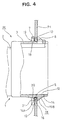
- the first and second elastic pushing portions 18, 20 are elastically deformed toward the escape grooves 19, 21 to a large degree as shown in FIG. 4.
- the first elastic pushing portion 18 elastically holds the upper side edge of the mount hole 5 in cooperation with the projections 8 due to its elastic restoring force.
- the preferably pair of second elastic pushing portions 20 elastically hold or position the lower side edge of the mount hole 5 in cooperation with the vertical surface 15A of the projected portion 15 of the elastic portion 12 due to their elastic restoring forces.
- the first and second elastic pushing portions 18, 20 are elastically deformed to a smaller degree as shown in FIG. 5, but display their elastic restoring forces. Similar to the other case, the first elastic pushing portion 18 elastically holds or positions the upper side edge of the mount hole 5 in cooperation with the projections 8 and the pair of the second elastic pushing portions 20 substantially elastically hold or position the lower side edge of the mount hole 5 in cooperation with the vertical surface 15A of the projected portion 15 of the elastic portion 12.
- the first and second elastic pushing portions 18, 20 elastically hold the upper and lower side edges of the mount hole 5 in cooperation with the projections 8 and/or the projected portion 15 of the elastic portion 12 which act as the side walls of the lock grooves 10, 16 while the degree of deformation thereof is substantially changed according to the thickness of the panel P.
- the connector M can be mounted in a proper position without any shake.
Landscapes
- Connector Housings Or Holding Contact Members (AREA)
- Details Of Connecting Devices For Male And Female Coupling (AREA)
- Casings For Electric Apparatus (AREA)
Applications Claiming Priority (3)
| Application Number | Priority Date | Filing Date | Title |
|---|---|---|---|
| JP9143844A JPH10335007A (ja) | 1997-06-02 | 1997-06-02 | コネクタ |
| JP143844/97 | 1997-06-02 | ||
| JP14384497 | 1997-06-02 |
Publications (2)
| Publication Number | Publication Date |
|---|---|
| EP0883213A2 true EP0883213A2 (de) | 1998-12-09 |
| EP0883213A3 EP0883213A3 (de) | 2000-03-29 |
Family
ID=15348271
Family Applications (1)
| Application Number | Title | Priority Date | Filing Date |
|---|---|---|---|
| EP98110028A Withdrawn EP0883213A3 (de) | 1997-06-02 | 1998-06-02 | Verbinder |
Country Status (4)
| Country | Link |
|---|---|
| US (1) | US6089909A (de) |
| EP (1) | EP0883213A3 (de) |
| JP (1) | JPH10335007A (de) |
| CN (1) | CN1201281A (de) |
Cited By (1)
| Publication number | Priority date | Publication date | Assignee | Title |
|---|---|---|---|---|
| EP3018767A1 (de) * | 2014-11-10 | 2016-05-11 | Tyco Electronics Corporation | Plattenmontierte kopfteilverbinder |
Families Citing this family (24)
| Publication number | Priority date | Publication date | Assignee | Title |
|---|---|---|---|---|
| US6568959B1 (en) * | 1998-01-15 | 2003-05-27 | The Siemon Company | Identification icon |
| US6334792B1 (en) | 1999-01-15 | 2002-01-01 | Adc Telecommunications, Inc. | Connector including reduced crosstalk spring insert |
| CN1320708C (zh) * | 1999-01-15 | 2007-06-06 | Adc电信股份公司 | 电信插座组件 |
| JP2000286022A (ja) * | 1999-03-31 | 2000-10-13 | Sharp Corp | 電子機器用端子コネクタ及び電子機器 |
| US6582132B1 (en) * | 2000-05-09 | 2003-06-24 | Molex Incorporated | Connector panel mount system |
| US6257925B1 (en) * | 2000-07-05 | 2001-07-10 | Hon Hai Precision Ind. Co., Ltd. | Pair of connectors clamping a printed circuit board |
| USD454113S1 (en) | 2000-11-28 | 2002-03-05 | Hirpse Electric Co., Ltd. | Electrical connector |
| US6767246B2 (en) | 2001-02-01 | 2004-07-27 | Amphenol Corporation | Snap-in relay socket system |
| US6623170B2 (en) * | 2001-06-20 | 2003-09-23 | Fci Americas Technology, Inc. | Angular mounted optical connector adaptor frame |
| US6814624B2 (en) * | 2002-11-22 | 2004-11-09 | Adc Telecommunications, Inc. | Telecommunications jack assembly |
| JP4093570B2 (ja) * | 2003-06-23 | 2008-06-04 | 住友電装株式会社 | コネクタ |
| CN2862418Y (zh) * | 2005-12-06 | 2007-01-24 | 富士康(昆山)电脑接插件有限公司 | 线缆连接器组件 |
| JP4508126B2 (ja) * | 2006-02-16 | 2010-07-21 | 住友電装株式会社 | コネクタ |
| US7708589B2 (en) * | 2007-06-22 | 2010-05-04 | Fci Americas Technology, Inc. | Panel-mount connectors with latching features |
| US8684443B2 (en) * | 2010-06-08 | 2014-04-01 | Suzuki Motor Corporation | Vehicular bezel mounting structure |
| CN103187670A (zh) * | 2011-12-30 | 2013-07-03 | 鸿富锦精密工业(武汉)有限公司 | 连接器固定装置 |
| JP2016012535A (ja) * | 2014-06-30 | 2016-01-21 | 住友電装株式会社 | コネクタの取付け構造 |
| USD847094S1 (en) | 2017-11-06 | 2019-04-30 | The Raymond Corporation | Connector |
| KR102695394B1 (ko) * | 2019-06-25 | 2024-08-14 | 한국단자공업 주식회사 | 패널장착형 커넥터 |
| US10985492B2 (en) * | 2019-07-19 | 2021-04-20 | Aptiv Technologies Limited | Connector shroud configuration |
| US20220285864A1 (en) * | 2019-07-29 | 2022-09-08 | Signify Holding B.V. | Electrical connector assembly |
| JP7230753B2 (ja) * | 2019-09-26 | 2023-03-01 | 住友電装株式会社 | コネクタ |
| JP7825131B2 (ja) * | 2022-05-24 | 2026-03-06 | 住友電装株式会社 | コネクタ |
| JP2025135093A (ja) * | 2024-03-05 | 2025-09-18 | 住友電装株式会社 | コネクタユニット |
Family Cites Families (16)
| Publication number | Priority date | Publication date | Assignee | Title |
|---|---|---|---|---|
| NL106553C (de) * | 1957-04-22 | |||
| US3366729A (en) * | 1967-03-31 | 1968-01-30 | Amp Inc | Electrical connector housing |
| BE715385A (de) * | 1967-06-15 | 1968-10-16 | ||
| US3523269A (en) * | 1968-03-08 | 1970-08-04 | Essex International Inc | Panel locking terminal connector block |
| US3790923A (en) * | 1972-04-04 | 1974-02-05 | Bunker Ramo | Electrical connector having improved panel mounting means and an improved releasable contact construction |
| US4840584A (en) * | 1988-02-05 | 1989-06-20 | Michael Cox | Mounting plate for attachment of electrical controls and accessories to walls and the like |
| US5002497A (en) * | 1990-01-26 | 1991-03-26 | Molex Incorporated | Floatable panel mountable electrical connector assembly |
| JP2520076B2 (ja) * | 1991-10-10 | 1996-07-31 | モレックス インコーポレーテッド | 電気コネクタ |
| JP2727869B2 (ja) * | 1992-05-29 | 1998-03-18 | 住友電装株式会社 | ボディ固定用コネクタ |
| JP2566190Y2 (ja) * | 1992-05-29 | 1998-03-25 | 住友電装株式会社 | ボディ固定用コネクタ |
| JP2973866B2 (ja) * | 1995-04-24 | 1999-11-08 | 住友電装株式会社 | 待ち受けコネクタ |
| JP3140336B2 (ja) * | 1995-08-01 | 2001-03-05 | 矢崎総業株式会社 | 可動コネクタ取付け構造 |
| JP3322788B2 (ja) * | 1996-01-29 | 2002-09-09 | 住友電装株式会社 | コネクタハウジング |
| JP3181021B2 (ja) * | 1996-04-17 | 2001-07-03 | 矢崎総業株式会社 | コネクタ保持構造 |
| US5752856A (en) * | 1996-07-30 | 1998-05-19 | The Whitaker Corporation | Sealed fuse connector |
| JP3189945B2 (ja) * | 1996-09-30 | 2001-07-16 | 矢崎総業株式会社 | 可動コネクタ |
-
1997
- 1997-06-02 JP JP9143844A patent/JPH10335007A/ja not_active Abandoned
-
1998
- 1998-05-28 US US09/086,137 patent/US6089909A/en not_active Expired - Fee Related
- 1998-06-02 CN CN98115068A patent/CN1201281A/zh active Pending
- 1998-06-02 EP EP98110028A patent/EP0883213A3/de not_active Withdrawn
Cited By (2)
| Publication number | Priority date | Publication date | Assignee | Title |
|---|---|---|---|---|
| EP3018767A1 (de) * | 2014-11-10 | 2016-05-11 | Tyco Electronics Corporation | Plattenmontierte kopfteilverbinder |
| US9766415B2 (en) | 2014-11-10 | 2017-09-19 | Te Connectivity Corporation | Panel mount header connector |
Also Published As
| Publication number | Publication date |
|---|---|
| US6089909A (en) | 2000-07-18 |
| JPH10335007A (ja) | 1998-12-18 |
| CN1201281A (zh) | 1998-12-09 |
| EP0883213A3 (de) | 2000-03-29 |
Similar Documents
| Publication | Publication Date | Title |
|---|---|---|
| US6089909A (en) | Connector | |
| US5252096A (en) | Connector | |
| EP1923962B1 (de) | Stecker und Vormontageverfahren dafür | |
| US6579113B2 (en) | Inertial locking connector | |
| EP0676828A2 (de) | Steckverbinder | |
| US6733346B2 (en) | Terminal fitting, a connector provided therewith and a method for forming a terminal fitting | |
| EP1104051B1 (de) | Verbinder | |
| US6386916B1 (en) | Connector | |
| EP1107380B1 (de) | Steckverbinder | |
| US7632138B2 (en) | Connector and a connector assembly | |
| US6497591B2 (en) | Connector | |
| EP1821372B1 (de) | Steckverbinder und Methode der Montage | |
| US6482035B2 (en) | Press-connecting connector | |
| JPH0584056U (ja) | 廻り止めコネクタ | |
| US7611370B2 (en) | Connector | |
| JPH10112355A (ja) | 電気コネクタのガタ防止構造 | |
| EP0940883B1 (de) | Halterungsaufbau für einen Steckverbinder | |
| JPH11126642A (ja) | ホルダ付コネクタ | |
| EP1391970B1 (de) | Verbinder | |
| US20030054690A1 (en) | Terminal fitting, a connector and a method for forming a terminal fitting | |
| US7033217B2 (en) | Connector | |
| EP1150388B1 (de) | Vorrichtung zur Verhinderung von Wackelbewegungen bei einem Anschlusskontakt sowie Verbinder | |
| US6238248B1 (en) | Connector for thin cartridge | |
| US7165993B2 (en) | Connector and method of molding a connector | |
| US7001224B2 (en) | Connector with retainer for locking terminal fitings |
Legal Events
| Date | Code | Title | Description |
|---|---|---|---|
| PUAI | Public reference made under article 153(3) epc to a published international application that has entered the european phase |
Free format text: ORIGINAL CODE: 0009012 |
|
| 17P | Request for examination filed |
Effective date: 19980626 |
|
| AK | Designated contracting states |
Kind code of ref document: A2 Designated state(s): DE FR GB IT |
|
| AX | Request for extension of the european patent |
Free format text: AL;LT;LV;MK;RO;SI |
|
| PUAL | Search report despatched |
Free format text: ORIGINAL CODE: 0009013 |
|
| AK | Designated contracting states |
Kind code of ref document: A3 Designated state(s): AT BE CH CY DE DK ES FI FR GB GR IE IT LI LU MC NL PT SE |
|
| AX | Request for extension of the european patent |
Free format text: AL;LT;LV;MK;RO;SI |
|
| AKX | Designation fees paid |
Free format text: DE FR GB IT |
|
| STAA | Information on the status of an ep patent application or granted ep patent |
Free format text: STATUS: THE APPLICATION HAS BEEN WITHDRAWN |
|
| 18W | Application withdrawn |
Withdrawal date: 20011221 |