EP0883259A2 - CDMA Empfänger für ein optisches Nachrichtenübertragungssystem und Verfahren zu dessen Betrieb - Google Patents
CDMA Empfänger für ein optisches Nachrichtenübertragungssystem und Verfahren zu dessen Betrieb Download PDFInfo
- Publication number
- EP0883259A2 EP0883259A2 EP98440106A EP98440106A EP0883259A2 EP 0883259 A2 EP0883259 A2 EP 0883259A2 EP 98440106 A EP98440106 A EP 98440106A EP 98440106 A EP98440106 A EP 98440106A EP 0883259 A2 EP0883259 A2 EP 0883259A2
- Authority
- EP
- European Patent Office
- Prior art keywords
- signal
- optical
- receiver
- output
- filter
- Prior art date
- Legal status (The legal status is an assumption and is not a legal conclusion. Google has not performed a legal analysis and makes no representation as to the accuracy of the status listed.)
- Withdrawn
Links
- 230000003287 optical effect Effects 0.000 title claims abstract description 54
- 230000005540 biological transmission Effects 0.000 title claims description 17
- 238000000034 method Methods 0.000 title claims description 13
- 230000000737 periodic effect Effects 0.000 claims abstract description 14
- 230000000295 complement effect Effects 0.000 claims description 10
- 238000004891 communication Methods 0.000 description 6
- 230000003595 spectral effect Effects 0.000 description 6
- 239000011521 glass Substances 0.000 description 4
- 239000011248 coating agent Substances 0.000 description 3
- 238000000576 coating method Methods 0.000 description 3
- 238000001914 filtration Methods 0.000 description 3
- 238000005259 measurement Methods 0.000 description 3
- 239000013307 optical fiber Substances 0.000 description 3
- 101100042610 Arabidopsis thaliana SIGB gene Proteins 0.000 description 2
- 229910013641 LiNbO 3 Inorganic materials 0.000 description 2
- 238000010586 diagram Methods 0.000 description 2
- 230000010354 integration Effects 0.000 description 2
- GQYHUHYESMUTHG-UHFFFAOYSA-N lithium niobate Chemical compound [Li+].[O-][Nb](=O)=O GQYHUHYESMUTHG-UHFFFAOYSA-N 0.000 description 2
- 238000001228 spectrum Methods 0.000 description 2
- 101100421503 Arabidopsis thaliana SIGA gene Proteins 0.000 description 1
- 101100420776 Arabidopsis thaliana SYN1 gene Proteins 0.000 description 1
- VUDQSRFCCHQIIU-UHFFFAOYSA-N DIF1 Natural products CCCCCC(=O)C1=C(O)C(Cl)=C(OC)C(Cl)=C1O VUDQSRFCCHQIIU-UHFFFAOYSA-N 0.000 description 1
- 101150001108 DIF1 gene Proteins 0.000 description 1
- 102100038546 Fibronectin type III and SPRY domain-containing protein 1 Human genes 0.000 description 1
- 101001030521 Homo sapiens Fibronectin type III and SPRY domain-containing protein 1 Proteins 0.000 description 1
- 101100396286 Homo sapiens IER3 gene Proteins 0.000 description 1
- 101100077149 Human herpesvirus 8 type P (isolate GK18) K5 gene Proteins 0.000 description 1
- 102100036900 Radiation-inducible immediate-early gene IEX-1 Human genes 0.000 description 1
- 101100294408 Saccharomyces cerevisiae (strain ATCC 204508 / S288c) MOT2 gene Proteins 0.000 description 1
- 230000007423 decrease Effects 0.000 description 1
- 230000001419 dependent effect Effects 0.000 description 1
- 230000000694 effects Effects 0.000 description 1
- 239000000835 fiber Substances 0.000 description 1
- 239000005357 flat glass Substances 0.000 description 1
- 239000000463 material Substances 0.000 description 1
- 108091084679 miR-3 stem-loop Proteins 0.000 description 1
- 108091033354 miR-3-1 stem-loop Proteins 0.000 description 1
- 108091058771 miR-3-2 stem-loop Proteins 0.000 description 1
- 230000010363 phase shift Effects 0.000 description 1
- 230000010287 polarization Effects 0.000 description 1
- 230000001105 regulatory effect Effects 0.000 description 1
- 101150117326 sigA gene Proteins 0.000 description 1
- 230000008054 signal transmission Effects 0.000 description 1
- 125000006850 spacer group Chemical group 0.000 description 1
Images



Classifications
-
- H—ELECTRICITY
- H04—ELECTRIC COMMUNICATION TECHNIQUE
- H04J—MULTIPLEX COMMUNICATION
- H04J14/00—Optical multiplex systems
- H04J14/005—Optical Code Multiplex
Definitions
- the invention relates to an optical receiver for an optical Message transmission system according to the preamble of claim 1 and a method for operating this messaging system according to the preamble of claim 3.
- a disadvantage of this method is that the periodicity of the filter functions of the transmitter and receiver must match very precisely (order of magnitude of 10 -5 relative). This requirement leads to an elaborate, regulated filter arrangement in order to compensate drifts in the filter function of the receiver, for example by temperature changes.
- Both alternative embodiments of the invention are common
- the basic idea is to provide means so that when the Receiver filter against a target filter function, a lower drop in Receiving power is achieved than before, in such a way that the Receiving power in the event of inadvertent detuning of the filter function the target filter function does not match the previous tuning curve with numerous sharp ones Runs through minima and maxima, but only their envelopes.
- An advantage of the invention is that the filter is stable to only about 1% needs and the requirement for the stability of the filter by at least is two orders of magnitude smaller than before.
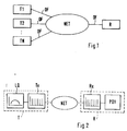
- FIG. 1 An optical message transmission system is shown in FIG. 1. It exists of N optical transmitters T1, ..., TN and an optical receiver R, the with each other via an optical communication network NET and optical fibers OF are connected.
- the messaging system can also contain other optical receivers.
- Optical message signals are used in the message transmission system coded transmission.
- the coding is done by filtering with the transmitting message modulated light signals in the transmitter.
- a periodic filter for example a Fabry-Perot interferometer or a Mach-Zehnder interferometer used.
- the decoding in the receiver is done by filtering the received message signals with a similar filter.
- the periodicities of the filter functions of Sender filter and receiver filter match, because only then will Receive a signal at the output of the receiver filter. It is advantageous here if the filters of the transmitter and receiver work independently of polarization.
- CDMA code division multiple access
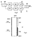
- the transmitter T contains a directly modulated, broadband signal light source LQ, for example a multi-mode laser with a wavelength spectrum from 1520 to 1580 nm or a light-emitting diode (LED), and a filter Tx.
- LQ directly modulated, broadband signal light source
- the receiver also has a filter Rx, to the output of which an optical receiving unit PD1, for example a photodetector or a photodiode, is connected.
- an optical receiving unit PD1 for example a photodetector or a photodiode
- a receiver R according to the invention is shown in a first exemplary embodiment in FIG.
- the message signal is split into two signal components at the IN input by a splitter KOP.
- the splitter KOP is connected to two optical filters Rx1, Rx2 in such a way that each optical filter Rx1, Rx2 receives one of the two signal components.
- the optical filters Rx1, Rx2 are detuned from one another in such a way that the round trip time ⁇ Rx2 of the second filter Rx2 differs from the round trip time ⁇ Rx1 of the first filter Rx1 by about a quarter of the mean light wave period of the received message signal.
- the filter Rx can be a Fabry-Perot interferometer, which consists of plane-parallel, partially mirrored glass plates. Another possibility is to use a Mach-Zehnder interferometer, for example based on lithium niobate (LiNbO 3 ).
- a Michelson interferometer, an arrayed waveguide grating or a Lyot filter can also be used.
- the round trip time is a characteristic of the filter.
- the path difference of a light wave between the two mirror surfaces of the interferometer i.e. the difference between the transit times between the mirror surfaces reflected light wave and a directly transmitted light wave.
- the Mach-Zehnder interferometer is the orbital period the difference in transit time a light wave between the two interferometer branches.
- the Message transmission a certain spectral range, for example 1520 up to 1580 nm, there is no exact detuning the round trip time of the second filter against the first.
- wavelength range would be a difference in the orbital times of 1.28fs (corresponds to a quarter light wave period at 1550nm) optimal.
- a difference in the tolerance range of 1.3fs ⁇ 10% is sufficient and with reasonable losses in insensitivity to the detuning of the Filter function also from 1.3fs ⁇ 20%.
- (1500nm corresponds to one Light wave period of 5fs, 1600nm of 5.33fs)
- this difference in round trip times as shown in Figure 4. It becomes the only Fabry-Perot interferometer FP used which as a first and a second filter area FB1, FB2 has first and second filters Rx1, Rx2. It consists of a glass plate GLASS coated on both sides with a partially permeable coating MIR1, MIR2 is mirrored. In the second filter area FB2 there is one on one side third coating MIR3 made of material with the same refractive index applied, the layer thickness of the third coating just like that is chosen to cause a difference in runtime of, for example, 1.3fs becomes.
- This Fabry-Perot interferometer FP is so in the receiver R in the Beam path adjusts that the two come from the KOP splitter Signal components SIG1, SIG2 each on one of the two filter areas FB1, FB2 to meet.
- the two filters Fx1, Fx2 in FIG. 3 each have a receiving unit PD1, PD2, for example a photodiode, which connects the optical Convert signals to electrical.
- a receiving unit PD1, PD2 At the exit of the two Receiving units PD1, PD2 are each a squaring device Q1, Q2 connected, which squares the amplitude of the two output signals.
- the two squared Output signals of the two squarers Q1, Q2 added.
- the result is a output signal OUT modulated with the transmitted message, which is extremely robust against changes in the filter function of both filters. It is sufficient if the filters are stable to an accuracy of 1%, only the difference in the round trip times of the two filters must be in the above specified limits remain.
- Rx1 and second Rx2 filter each filter with two outputs P11, P12, P21, P22 used, each deliver complementary output signals. With Complementarily it is indicated that the sum of both output signals is Input signal of the respective filter results.
- the two output signals are each in two separate receiving units PD1, PD3 and PD2, PD4 converted into electrical signals.
- the two electrical signals coming from the mutually complementary output signals of one of the filters Rx1, Rx2 are then generated in a differential amplifier DIF1, DIF2 of subtracted from each other.
- This has the advantage of being crosstalk from others Channels is reduced.
- an adjustable attenuator dB which between the second output of each filter and the respective one Receiving unit is arranged, crosstalk can be particularly effective be compensated.
- the two are complementary output signals of the transmitted and the reflected portion of the input signal received from the splitter KOP.
- the reflected part can by means of another splitter, not shown, from the at the entrance IN coupled optical fiber.
- a Mach-Zehnder interferometer that has two Output branches, are the two complementary output signals the signal components of the received message signal from the two Output branches.
- FIG. 6 An alternative device according to the invention, the same Basic principle acts, is shown in Figure 6 in a third embodiment.
- the filter function only consumes about 1% Accuracy to be stabilized.
- the front of the receiving unit PD1 switched filter Rx connected to a modulation device MOD the modulates the filter function of the filter Rx with a frequency f that is greater, than the bit repetition rate of received message signals.
- the Receiving unit PD1 delivers at its output one with the transmitted one Message modulated electrical signal.
- the filter Rx can be a Fabry-Perot interferometer, which consists of plane-parallel, partially mirrored glass plates, between which a piezo element is attached as a spacer. By applying a modulation voltage with a sinusoidal shape to the piezo element, the distance between the glass plates is varied and the filter function of the filter is thereby modulated.
- a Mach-Zehnder interferometer for example based on lithium niobate (LiNbO 3 ), in which the optical path length in one of the interferometer branches can be changed by applying a modulation voltage. In this embodiment, too, the filter function is modulated.
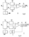
- FIG 5 A further development based on the first exemplary embodiment is shown in a second embodiment.
- a filter Rx with two outputs P1, P2 used the complementary output signals deliver.
- Complementary means that the sum of the two Output signals gives the input signal.
- the two output signals are converted into electrical signals in two separate receiving units PD1, PD2 converted, then in a differential amplifier DIF from each other subtracted from. This has the advantage of being crosstalk from others Channels is reduced.
- the two are complementary output signals of the transmitted and the reflected portion that received from the communications network Message signals.
- the reflected portion can be split decoupled from the optical fiber connected to the IN input will. It is then advantageous between the output for the reflected Signal portion and the differential amplifier an adjustable attenuator to provide.
- these are two complementary output signals the signal components of the received Message signals from the two output branches of the interferometer.
- the sixth embodiment shown in FIG. 9 represents a special one simple implementation of the rectifier from the third embodiment
- the rectifier contains a multiplication device M and one Integrator INT.
- the bipolar output signal of the differential amplifier DIF is in the multiplier M with the frequency signal of the modulation device multiplied.
- the frequency signal is the same Frequency signal with which the filter Rx is modulated.
- Multiplication of this frequency signal by the output signal of the Differential amplifier DIF and subsequent integration with one downstream integrator INT will rectify the Output signals reached.
- the integrator INT integrates the output signal of the multiplication device M over a period of a period of the bit repetition rate of received message signal corresponds.
- the operation of the invention is that if the Receiver filter against a target filter function, a lower drop in Receiving power is achieved than before, in such a way that the Receiving power in the event of inadvertent detuning of the filter function the target filter function does not match the previous tuning curve with numerous sharp ones Runs through minima and maxima, but only their envelopes.
- the filter function T (f), ie the pass function, which indicates which portion of the signal is passed through the filter as a function of the frequency f of a incoming signal, is given by: (with ⁇ as the round trip time of the filter) T (f) ⁇ 1 + cos (2 ⁇ f ⁇ )
- T Tx (f) is the filter function of the transmission filter
- T Rx (f) is the filter function of the receiver filter
- S (f) is the spectral distribution of the signal light source in the transmitter.
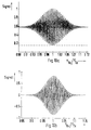
- This tuning curve is shown in FIG. 10a for a Gaussian spectral distribution of the signal light source.
- the relative detuning of the receiver filter from the transmitter filter expressed as the quotient of the round trip times of the filters ⁇ Rx / ⁇ Tx, is plotted as the abscissa.
- the received power normalized to the total power of the light source is plotted as the ordinate.
- the tuning curve has clearly recognizable sharp maxima and minima, while the envelope of the tuning curve only slowly strives towards an average value that can be subtracted as a constant offset.
- Figure 10b is the tuning curve for the case of a bipolar Output signal using the shown in Figure 5 and Figure 7-9 Differential amplifier shown to reduce crosstalk.
- the basic idea of the invention is to provide measures by which, if the receiver filter is out of tune, is not that in FIGS 10b shown tuning curve, but the envelope is traversed. This will cause signal dips if the receiver filter is detuned avoided by the sharp minima of the tuning curve.
- a second filter is used for this.
- the signal portion passed by this runs through a second tuning curve when detuned.
- the function under the envelope of the tuning curve is a cosine function.
- the second filter is detuned from the first so that the tuning curve of the second is shifted from the tuning curve of the first filter by a quarter period of this cosine function.
- This corresponds to a phase shift of the cosine function of ⁇ / 4, which is known to result in a sine function from the cosine function. From the general relationship The reason is based on the fact that the envelope of the tuning curves is obtained by squaring and then adding the signal components obtained from the two filters
- FIG. 11 A measurement curve is shown in FIG. 11 which illustrates this. Like FIGS. 10a and 10b, it shows the received power (signal) normalized to the total power of the light source plotted against the relative detuning ( ⁇ Rx / ⁇ Tx ) of the receiver filter against the transmitter filter.
- the measurement curve was recorded with the structure of the second exemplary embodiment (FIG. 5) and represents the envelope of the tuning curve from FIG. 10b.
- first of all modulated light signals for example by means of a directly modulated, broadband light source are generated with a periodic transmitter filter encoded.
- the coded light signals are transmitted via a Message transmission network transmitted and in a receiver after a the types described in the exemplary embodiments again by means of Receiver filter decoded and into electrical by means of the receiving unit Signals converted.
- This transmission method has the particular advantage that also complex control of the transmitter filter can be dispensed with in the transmitter can, since it also applies to the transmitter filter that its filter function only to about 1% accuracy needs to be stable.
- Improvement in the receiver will therefore simplify the transmitter achieved, which ultimately leads to the transmitter with less effort and can be produced at a lower cost than before.
Landscapes
- Engineering & Computer Science (AREA)
- Computer Networks & Wireless Communication (AREA)
- Signal Processing (AREA)
- Optical Communication System (AREA)
- Mechanical Light Control Or Optical Switches (AREA)
- Small-Scale Networks (AREA)
Abstract
Description
- Fig.1
- Ein optisches Nachrichtenübertragungssystem mit Sendern und einem Empfänger,
- Fig.2
- ein optisches Nachrichtenübertragungssystem mit einem Sender und einem Empfänger,
- Fig.3
- ein Blockdiagramm eines erfindungsgemäßen Empfängers,
- Fig.4
- die Filteranordnung des Empfängers aus Fig.3,
- Fig.5
- eine Weiterbildung des Empfängers aus Figur 3,
- Fig.6
- ein Blockdiagramm eines anderen erfindungsgemäßen Empfängers,
- Fig.7
- eine Weiterbildung des Empfängers aus Figur 6,
- Fig.8
- eine Weiterbildung des Empfängers aus Figur 7,
- Fig.9
- eine Weiterbildung des Empfängers aus Figur 8,
- Fig.10a
- eine erste Meßkurve der Empfangsleistung bei Verstimmung des Empfängerfilters,
- Fig.10b
- eine zweite Meßkurve der Empfangsleistung bei Verstimmung des Empfängerfilters und
- Fig.11
- eine dritte Meßkurve der Empfangsleistung bei Verstimmung des Empfängerfilters.


Claims (10)
- Empfänger (R) für ein optisches Nachrichtenübertragungssystem zur Übertragung kodierter optischer Nachrichtensignale, mit einer ersten optischen Empfangseinheit (PD1), der eine erste periodische optische Filtervorrichtung (Rx1) vorgeschaltet ist,
gekennzeichnet durch,eine zweite periodische optische Filtervorrichtung (Rx2), deren Umlaufzeit gegenüber der Umlaufzeit der ersten Filtervorrichtung um etwa ein Viertel der mittleren Lichtwellenperiode des empfangenen Nachrichtensignales verstimmt ist,einen optischen Splitter (KOP), über den die Eingänge der ersten und der zweiten Filtervorrichtung (Rx1, Rx2) mit dem Eingang (IN) des Empfängers (R) verbunden sind,eine zweite der zweiten Filtervorrichtung (Rx2) nachgeschaltete optische Empfangseinheit (PD2),zwei Quadriereinrichtungen (Q1, Q2), die jeweils einer der beiden optischen Empfangseinheit (PD1, PD2) nachgeschaltet sind, um die Amplitude des ihr jeweils zugeführten Signales zu quadrieren undeine Addiervorrichtung (AD) um die Ausgangssignale der beiden Quadriereinrichtungen (Q1, Q2) zu addieren. - Empfänger (R) nach Anspruch 1,bei dem zumindest die erste Filtervorrichtung (Rx1) neben dem ersten Ausgang (P11), der mit der ersten optischen Empfangseinheit (PD1) verbunden ist, einen zweiten Ausgang (P12) umfaßt, dessen Ausgangssignal komplementär zu dem Ausgangssignal des ersten Ausganges (P11) ist und der mit einer dritten optischen Empfangseinheit (PD3) verbunden ist, undder einen Differenzverstärker (DIF) aufweist, der das Ausgangssignal der dritten optischen Empfangseinheit (PD3) von dem Ausgangssignal der ersten optischen Empfangseinheit (PD1) subtrahiert.
- Verfahren zum Übertragen von kodierten optischen Nachrichtensignalen in einem optischen Nachrichtenübertragungssystem, wobei das Nachrichtensignal in einem Sender (T) mittels eines Senderfilters (Tx) kodiert wird und in einem Empfänger (R) mittels einer ersten periodischen optischen Filtervorrichtung (Rxl) dekodiert und mittels einer ersten Empfangseinheit (PD1) in ein erstes elektrisches Signal umgewandelt wird,
dadurch gekennzeichnet, daßdas kodierte optische Nachrichtensignal vor dem Dekodieren mittels eines optischen Splitters (KOP) aufgeteilt wird und der ersten (Rx1) und einer zweiten Filtervorrichtung (Rx2) zugeleitet wird, deren Umlaufzeit gegenüber der Umlaufzeit der ersten Filtervorrichtung (Rx1) um etwa ein Viertel der mittleren Lichtwellenperiode des empfangenen Nachrichtensignales verstimmt ist,der in der zweiten Filtervorrichtung (Rx2) gefilterte Signalanteil mittels einer zweiten Empfangseinheit (PD2) in ein zweites elektrisches Signal umgewandelt wird,die Amplitude des ersten elektrischen Signales mittels einer ersten Quadriereinrichtung (Q1) und die Amplitude des zweiten elektrischen Signales mittels einer zweiten Quadriereinrichtung (Q2) quadriert werden und daßdie beiden quadrierten elektrischen Signale mittels einer Addiervorrichtung (AD) addiert werden. - Empfänger (R) für ein optisches Nachrichtenübertragungssystem zur Übertragung kodierter optischer Nachrichtensignale, mit einer optischen Empfangseinheit (PD1), der eine periodische optische Filtervorrichtung (Rx) vorgeschaltet ist,
gekennzeichnet durch,
eine Modulationseinrichtung (MOD) zur Modulation der Filterfunktion der Filtervorrichtung (Rx) mit einer Frequenz, die größer ist, als die Bitwiederholrate der empfangenen Nachrichtensignale. - Empfänger (R) nach Anspruch 4,bei dem die Filtervorrichtung (Rx) neben dem ersten Ausgang (P1), der mit der ersten optischen Empfangseinheit (PD1) verbunden ist, einen zweiten Ausgang (P2) umfaßt, dessen Ausgangssignal komplementär zu dem Ausgangssignal des ersten Ausganges (P1) ist und der mit einer zweiten optischen Empfangseinheit (PD2) verbunden ist, undder einen Differenzverstärker (DIF) aufweist, der das Ausgangssignal der zweiten optischen Empfangseinheit (PD2) von dem Ausgangssignal der ersten optischen Empfangseinheit (PD1) subtrahiert.
- Empfänger nach Anspruch 5, bei dem dem Differenzverstärker (DIF) ein Gleichrichter (GL) nachgeschaltet ist.
- Emfpänger nach Anspruch 6, bei dem der Gleichrichter (GL) eine Multiplikationsvorrichtung (M), welche das Ausgangssignal des Differenzverstärkers (DIF) mit dem Ausgangssignal der Modulationsvorrichtung (MOD) multipliziert, und einen der Multiplikationsvorrichtung (M) nachgeschalteten Integrator (INT) enthält, der über eine Periode der Bitwiderholrate des empfangenen Nachrichtensignales integriert.
- Verfahren zum Übertragen von kodierten optischen Nachrichtensignalen in einem optischen Nachrichtenübertragungssystem, wobei das Nachrichtensignal in einem Sender (T) mittels eines Senderfilters (Tx) kodiert wird und in einem Empfänger (R) mittels einer periodischen optischen Filtervorrichtung (Rx1) dekodiert und mittels einer Empfangseinheit (PD1) in ein elektrisches Signal umgewandelt wird,
dadurch gekennzeichnet, daß
die Filterfunktion der Filtervorrichtung (Rx) mit einer Frequenz, die größer ist als die Bitwiederholrate der empfangenen Nachrichtensignale mittels einer Modulationseinrichtung (MOD) moduliert wird. - Empfänger nach einem der Ansprüche 2 oder 5, bei dem die Filtervorrichtung (Rx1, Rx) ein Fabry-Perot-lnterferometer ist und bei dem das Ausgangssignal des ersten Ausgangs (P11, P1) der transmittierte Signalanteil des empfangenen Nachrichtensignales ist und das Ausgangssignal des zweiten Ausgangs (P12, P2) der reflektierte Signalanteil des empfangenen Nachrichtensignales ist.
- Empfänger nach einem der Ansprüche 2 oder 5, bei dem die Filtervorrichtung (Rx, Rx1) ein Mach-Zehnder-Interferometer mit zwei Ausgangszweigen ist und bei dem die beiden Ausgangssignale die beiden Signalanteile des empfangenen Nachrichtensignales aus den beiden Ausgangszweigen des Mach-Zehnder-lnterferometers sind.
Applications Claiming Priority (3)
| Application Number | Priority Date | Filing Date | Title |
|---|---|---|---|
| DE19722370 | 1997-05-28 | ||
| DE19722370A DE19722370A1 (de) | 1997-05-28 | 1997-05-28 | Empfänger für ein optisches Nachrichtenübertragungssystem und Verfahren zu dessen Betrieb |
| US09/085,517 US6404528B1 (en) | 1997-05-28 | 1998-05-27 | Receiver for an optical communications system and method for operating such a system |
Publications (2)
| Publication Number | Publication Date |
|---|---|
| EP0883259A2 true EP0883259A2 (de) | 1998-12-09 |
| EP0883259A3 EP0883259A3 (de) | 2004-03-31 |
Family
ID=26036931
Family Applications (1)
| Application Number | Title | Priority Date | Filing Date |
|---|---|---|---|
| EP98440106A Withdrawn EP0883259A3 (de) | 1997-05-28 | 1998-05-25 | CDMA Empfänger für ein optisches Nachrichtenübertragungssystem und Verfahren zu dessen Betrieb |
Country Status (5)
| Country | Link |
|---|---|
| US (1) | US6404528B1 (de) |
| EP (1) | EP0883259A3 (de) |
| JP (1) | JPH118594A (de) |
| CA (1) | CA2235834A1 (de) |
| DE (1) | DE19722370A1 (de) |
Cited By (3)
| Publication number | Priority date | Publication date | Assignee | Title |
|---|---|---|---|---|
| WO2000070804A1 (en) * | 1999-05-17 | 2000-11-23 | Codestream Technologies Corporation | Photonic integrated circuit for optical cdma |
| WO2000076102A1 (en) * | 1999-05-17 | 2000-12-14 | Codestream Technologies Corporation | Optical cdma using a cascaded mask structure |
| EP1274184A3 (de) * | 2001-07-03 | 2004-05-19 | Alcatel | Empfänger zum Empfang von optischen Signalen |
Families Citing this family (19)
| Publication number | Priority date | Publication date | Assignee | Title |
|---|---|---|---|---|
| EP1222762B1 (de) * | 1999-10-21 | 2006-03-01 | Nokia Corporation | Optisches telekommunikations-zugangsnetz |
| US6594055B2 (en) | 2001-01-17 | 2003-07-15 | Oyster Optics, Inc. | Secure fiber optic telecommunications system and method |
| US6469816B1 (en) | 2001-05-24 | 2002-10-22 | Oyster Optics, Inc. | Phase-modulated fiber optic telecommunications system |
| US6476952B1 (en) | 2001-01-17 | 2002-11-05 | Oyster Optics, Inc. | Phase-modulated fiber optic telecommunications system |
| US20020131106A1 (en) * | 2001-03-16 | 2002-09-19 | Peter Snawerdt | Secure wave-division multiplexing telecommunications system and method |
| EP1405444B1 (de) * | 2001-07-09 | 2013-01-23 | TQ Gamma, LLC | Faseroptische telekommunikationskarte mit sicherheitserkennung |
| FR2827971B1 (fr) * | 2001-07-27 | 2003-10-10 | Thales Sa | Reseau de communications optiques, multi-utilisateurs, reconfigurable a faible temps de latence |
| JP3690321B2 (ja) * | 2001-10-01 | 2005-08-31 | 住友電気工業株式会社 | 波長検出装置、マルチモード半導体レーザモジュール、波長安定化装置およびラマン増幅器 |
| US20030174423A1 (en) * | 2002-03-15 | 2003-09-18 | Hart Brian T. | Monolithic filter array |
| US20030174424A1 (en) * | 2002-03-15 | 2003-09-18 | Hart Brian T. | Monolithic filter array |
| US7260330B2 (en) * | 2002-11-04 | 2007-08-21 | The Boeing Company | Optical communication system using correlation receiver |
| JP4592588B2 (ja) * | 2003-02-07 | 2010-12-01 | パナソニック株式会社 | 光伝送システム |
| EP1458070A1 (de) * | 2003-03-12 | 2004-09-15 | Agilent Technologies Inc. a Delaware Corporation | Optische Wellenlängen Überprüfungsanlage |
| US20050015546A1 (en) * | 2003-07-15 | 2005-01-20 | Ofir Zohar | Data storage system |
| JPWO2006018952A1 (ja) | 2004-08-20 | 2008-05-08 | 松下電器産業株式会社 | 多モード光伝送装置 |
| TWI375846B (en) * | 2005-09-23 | 2012-11-01 | Hon Hai Prec Ind Co Ltd | Opto-electronic frequency multiplier |
| EP1850170A1 (de) * | 2006-08-01 | 2007-10-31 | Alcatel Lucent | Feineinstellung eines integrierten Wellenlängenmonitors |
| US7672938B2 (en) * | 2007-10-05 | 2010-03-02 | Microsoft Corporation | Creating search enabled web pages |
| US8032036B2 (en) * | 2007-12-10 | 2011-10-04 | Verizon Patent And Licensing Inc. | DQPSK/DPSK optical receiver with tunable optical fibers |
Family Cites Families (8)
| Publication number | Priority date | Publication date | Assignee | Title |
|---|---|---|---|---|
| US4703474A (en) | 1986-02-28 | 1987-10-27 | American Telephone And Telegraph Company, At&T Bell Laboratories | Spread spectrum code-division-multiple-access (SS-CDMA) lightwave communication system |
| CA1279414C (en) | 1987-06-26 | 1991-01-22 | Makoto Nishio | Apparatus for discriminating an optical signal from others and an apparatus for tuning an optical wavelength filter used in the same |
| DE3907497A1 (de) | 1989-03-08 | 1990-09-13 | Standard Elektrik Lorenz Ag | Optisches nachrichtenuebertragungssystem fuer den teilnehmeranschlussbereich |
| FR2681953B1 (fr) | 1991-10-01 | 1993-11-05 | Thomson Csf | Correlateur de frequences. |
| JPH06224882A (ja) * | 1992-10-03 | 1994-08-12 | Canon Inc | 光fsk受信器及びそれを用いた光fdm−fsk伝送システム |
| JPH06237242A (ja) | 1993-02-09 | 1994-08-23 | Fujitsu Ltd | 光フィルタとその透過波長制御方法及びこれを用いた 光受信器 |
| US5459461A (en) * | 1993-07-29 | 1995-10-17 | Crowley; Robert J. | Inflatable keyboard |
| US5903393A (en) * | 1997-12-04 | 1999-05-11 | Kalibjian; Ralph | Optical-hybrid etalons for simultaneous phase- and polarization-diversity operations |
-
1997
- 1997-05-28 DE DE19722370A patent/DE19722370A1/de not_active Withdrawn
-
1998
- 1998-05-25 CA CA002235834A patent/CA2235834A1/en not_active Abandoned
- 1998-05-25 EP EP98440106A patent/EP0883259A3/de not_active Withdrawn
- 1998-05-27 JP JP10145766A patent/JPH118594A/ja active Pending
- 1998-05-27 US US09/085,517 patent/US6404528B1/en not_active Expired - Fee Related
Non-Patent Citations (2)
| Title |
|---|
| KAVEHRAD M ET AL: "OPTICAL CODE-DIVISION-MULTIPLEXED SYSTEMS BASED ON SPECTRAL ENCODING OF NONCOHERENT SOURCES" JOURNAL OF LIGHTWAVE TECHNOLOGY, IEEE. NEW YORK, US, Bd. 13, Nr. 3, 1. M{rz 1995 (1995-03-01), Seiten 534-545, XP000509320 ISSN: 0733-8724 * |
| MOELLER L: "AN OPTICAL CDMA METHOD BASED ON PERIODIC SPECTRUM ENCODING" PROCEEDINGS OF THE ANNUAL CONFERENCE ON EUROPEAN FIBRE OPTIC COMMUNICATIONS AND NETWORKS (EFOC), XX, XX, 27. Juni 1995 (1995-06-27), Seiten 178-181, XP000672568 * |
Cited By (3)
| Publication number | Priority date | Publication date | Assignee | Title |
|---|---|---|---|---|
| WO2000070804A1 (en) * | 1999-05-17 | 2000-11-23 | Codestream Technologies Corporation | Photonic integrated circuit for optical cdma |
| WO2000076102A1 (en) * | 1999-05-17 | 2000-12-14 | Codestream Technologies Corporation | Optical cdma using a cascaded mask structure |
| EP1274184A3 (de) * | 2001-07-03 | 2004-05-19 | Alcatel | Empfänger zum Empfang von optischen Signalen |
Also Published As
| Publication number | Publication date |
|---|---|
| CA2235834A1 (en) | 1998-11-28 |
| EP0883259A3 (de) | 2004-03-31 |
| DE19722370A1 (de) | 1998-12-03 |
| JPH118594A (ja) | 1999-01-12 |
| US6404528B1 (en) | 2002-06-11 |
Similar Documents
| Publication | Publication Date | Title |
|---|---|---|
| EP0883259A2 (de) | CDMA Empfänger für ein optisches Nachrichtenübertragungssystem und Verfahren zu dessen Betrieb | |
| EP0554736B1 (de) | Digitales optisches Nachrichtenübertragungssystem mit einem bei der Betriebswellenlänge dispersionsbehafteten Lichtwellenleiter | |
| DE69013662T2 (de) | Schmalbandige Laserquelle. | |
| DE69410187T2 (de) | Vorrichtung zum Auskoppeln und Wiedereinkoppeln eines optischen Trägersignals in optische Kommunikationsnetzwerke | |
| DE69524872T2 (de) | Wellenlängenmultiplexierter optischer modulator | |
| DE69603141T2 (de) | Dispersionskompensation | |
| DE69320101T2 (de) | Unterdrücken von Rauschen und Verzerrungen in einem Lichtwellenleitersystem | |
| DE68926195T2 (de) | Stabilisierungsverfahren für eine Frequenztrennung in einer optischen heterodynen oder homodynen Übertragung | |
| DE69233151T2 (de) | Polarisationsmultiplexierung mit solitons | |
| DE3782556T2 (de) | Lichtuebertragungssystem. | |
| DE69626578T2 (de) | Anordnung zur Reduzierung von durch Vierwellenmischung verursachtem optischen Rauschen | |
| DE69210506T2 (de) | Frequenzmoduliertes kohärentes optisches Übertragungssystem mit kontinuierlicher Polarisationsverwürflung | |
| DE69833913T2 (de) | Unterdrückung des kohärenten Rayleighrauschens in bidirektionalen Übertragungssystemen | |
| DE69019811T2 (de) | Netzwerk mit Vielfachzugriff durch Frequenzmultiplexierung. | |
| EP0480231B1 (de) | Optisches Sende- und Empfangsmodul | |
| DE3637809A1 (de) | Sender fuer kohaerente lichtwellen | |
| DE60126479T2 (de) | Vorrichtung zur mehrwertigen Modulation | |
| EP1026849A2 (de) | Optisches Übertragungssystem sowie Sender und Empfänger | |
| EP0261479B1 (de) | Optischer Überlagerungsempfänger | |
| DE60218546T2 (de) | Optisches kommunikationssystem | |
| EP0288418B1 (de) | Verfahren zur optischen Nachrichtenübertragung mit Heterodynempfang | |
| EP0657765B1 (de) | Optischer Phasenregelkreis | |
| EP1271811B1 (de) | Verfahren und Vorrichtung zur Verstärkung von WDM Signalen mittels des stimulierten Brillouin-Streuprozess | |
| EP0881789B1 (de) | Empfänger für ein optisches Nachrichtenübertragungssystem, Filtervorrichtung und Verfahren zu dessen Betrieb | |
| DE69214531T2 (de) | Kohärentes faseroptisches Übertragungssystem mit Polarisationsmodulation |
Legal Events
| Date | Code | Title | Description |
|---|---|---|---|
| PUAI | Public reference made under article 153(3) epc to a published international application that has entered the european phase |
Free format text: ORIGINAL CODE: 0009012 |
|
| AK | Designated contracting states |
Kind code of ref document: A2 Designated state(s): AT BE CH CY DE DK ES FI FR GB GR IE IT LI LU MC NL PT SE |
|
| AX | Request for extension of the european patent |
Free format text: AL;LT;LV;MK;RO;SI |
|
| RAP3 | Party data changed (applicant data changed or rights of an application transferred) |
Owner name: ALCATEL |
|
| PUAL | Search report despatched |
Free format text: ORIGINAL CODE: 0009013 |
|
| AK | Designated contracting states |
Kind code of ref document: A3 Designated state(s): AT BE CH CY DE DK ES FI FR GB GR IE IT LI LU MC NL PT SE |
|
| AX | Request for extension of the european patent |
Extension state: AL LT LV MK RO SI |
|
| RIC1 | Information provided on ipc code assigned before grant |
Ipc: 7H 04J 14/00 A |
|
| AKX | Designation fees paid |
Designated state(s): DE FI FR GB IT SE |
|
| STAA | Information on the status of an ep patent application or granted ep patent |
Free format text: STATUS: THE APPLICATION IS DEEMED TO BE WITHDRAWN |
|
| 18D | Application deemed to be withdrawn |
Effective date: 20041201 |