EP0883509B1 - Systeme de commande d'embrayage - Google Patents
Systeme de commande d'embrayage Download PDFInfo
- Publication number
- EP0883509B1 EP0883509B1 EP97950287A EP97950287A EP0883509B1 EP 0883509 B1 EP0883509 B1 EP 0883509B1 EP 97950287 A EP97950287 A EP 97950287A EP 97950287 A EP97950287 A EP 97950287A EP 0883509 B1 EP0883509 B1 EP 0883509B1
- Authority
- EP
- European Patent Office
- Prior art keywords
- clutch
- kiss
- point
- engine
- speed
- Prior art date
- Legal status (The legal status is an assumption and is not a legal conclusion. Google has not performed a legal analysis and makes no representation as to the accuracy of the status listed.)
- Expired - Lifetime
Links
- 238000000034 method Methods 0.000 claims abstract description 29
- 238000005259 measurement Methods 0.000 claims abstract description 23
- 230000005540 biological transmission Effects 0.000 claims abstract description 22
- 230000002035 prolonged effect Effects 0.000 claims description 3
- 230000001052 transient effect Effects 0.000 claims description 2
- 230000007306 turnover Effects 0.000 description 6
- 239000003795 chemical substances by application Substances 0.000 description 3
- 238000010586 diagram Methods 0.000 description 2
- 230000000694 effects Effects 0.000 description 2
- 239000000446 fuel Substances 0.000 description 2
- 239000007858 starting material Substances 0.000 description 2
- 230000007423 decrease Effects 0.000 description 1
- 230000000994 depressogenic effect Effects 0.000 description 1
- 238000001914 filtration Methods 0.000 description 1
- 238000013178 mathematical model Methods 0.000 description 1
Images

Classifications
-
- B—PERFORMING OPERATIONS; TRANSPORTING
- B60—VEHICLES IN GENERAL
- B60W—CONJOINT CONTROL OF VEHICLE SUB-UNITS OF DIFFERENT TYPE OR DIFFERENT FUNCTION; CONTROL SYSTEMS SPECIALLY ADAPTED FOR HYBRID VEHICLES; ROAD VEHICLE DRIVE CONTROL SYSTEMS FOR PURPOSES NOT RELATED TO THE CONTROL OF A PARTICULAR SUB-UNIT
- B60W30/00—Purposes of road vehicle drive control systems not related to the control of a particular sub-unit, e.g. of systems using conjoint control of vehicle sub-units
- B60W30/18—Propelling the vehicle
-
- B—PERFORMING OPERATIONS; TRANSPORTING
- B60—VEHICLES IN GENERAL
- B60W—CONJOINT CONTROL OF VEHICLE SUB-UNITS OF DIFFERENT TYPE OR DIFFERENT FUNCTION; CONTROL SYSTEMS SPECIALLY ADAPTED FOR HYBRID VEHICLES; ROAD VEHICLE DRIVE CONTROL SYSTEMS FOR PURPOSES NOT RELATED TO THE CONTROL OF A PARTICULAR SUB-UNIT
- B60W10/00—Conjoint control of vehicle sub-units of different type or different function
- B60W10/02—Conjoint control of vehicle sub-units of different type or different function including control of driveline clutches
-
- B—PERFORMING OPERATIONS; TRANSPORTING
- B60—VEHICLES IN GENERAL
- B60W—CONJOINT CONTROL OF VEHICLE SUB-UNITS OF DIFFERENT TYPE OR DIFFERENT FUNCTION; CONTROL SYSTEMS SPECIALLY ADAPTED FOR HYBRID VEHICLES; ROAD VEHICLE DRIVE CONTROL SYSTEMS FOR PURPOSES NOT RELATED TO THE CONTROL OF A PARTICULAR SUB-UNIT
- B60W10/00—Conjoint control of vehicle sub-units of different type or different function
- B60W10/10—Conjoint control of vehicle sub-units of different type or different function including control of change-speed gearings
-
- B—PERFORMING OPERATIONS; TRANSPORTING
- B60—VEHICLES IN GENERAL
- B60W—CONJOINT CONTROL OF VEHICLE SUB-UNITS OF DIFFERENT TYPE OR DIFFERENT FUNCTION; CONTROL SYSTEMS SPECIALLY ADAPTED FOR HYBRID VEHICLES; ROAD VEHICLE DRIVE CONTROL SYSTEMS FOR PURPOSES NOT RELATED TO THE CONTROL OF A PARTICULAR SUB-UNIT
- B60W10/00—Conjoint control of vehicle sub-units of different type or different function
- B60W10/10—Conjoint control of vehicle sub-units of different type or different function including control of change-speed gearings
- B60W10/11—Stepped gearings
-
- B—PERFORMING OPERATIONS; TRANSPORTING
- B60—VEHICLES IN GENERAL
- B60W—CONJOINT CONTROL OF VEHICLE SUB-UNITS OF DIFFERENT TYPE OR DIFFERENT FUNCTION; CONTROL SYSTEMS SPECIALLY ADAPTED FOR HYBRID VEHICLES; ROAD VEHICLE DRIVE CONTROL SYSTEMS FOR PURPOSES NOT RELATED TO THE CONTROL OF A PARTICULAR SUB-UNIT
- B60W30/00—Purposes of road vehicle drive control systems not related to the control of a particular sub-unit, e.g. of systems using conjoint control of vehicle sub-units
- B60W30/18—Propelling the vehicle
- B60W30/1819—Propulsion control with control means using analogue circuits, relays or mechanical links
-
- F—MECHANICAL ENGINEERING; LIGHTING; HEATING; WEAPONS; BLASTING
- F16—ENGINEERING ELEMENTS AND UNITS; GENERAL MEASURES FOR PRODUCING AND MAINTAINING EFFECTIVE FUNCTIONING OF MACHINES OR INSTALLATIONS; THERMAL INSULATION IN GENERAL
- F16D—COUPLINGS FOR TRANSMITTING ROTATION; CLUTCHES; BRAKES
- F16D48/00—External control of clutches
- F16D48/06—Control by electric or electronic means, e.g. of fluid pressure
- F16D48/066—Control of fluid pressure, e.g. using an accumulator
-
- B—PERFORMING OPERATIONS; TRANSPORTING
- B60—VEHICLES IN GENERAL
- B60W—CONJOINT CONTROL OF VEHICLE SUB-UNITS OF DIFFERENT TYPE OR DIFFERENT FUNCTION; CONTROL SYSTEMS SPECIALLY ADAPTED FOR HYBRID VEHICLES; ROAD VEHICLE DRIVE CONTROL SYSTEMS FOR PURPOSES NOT RELATED TO THE CONTROL OF A PARTICULAR SUB-UNIT
- B60W2510/00—Input parameters relating to a particular sub-units
- B60W2510/02—Clutches
- B60W2510/0208—Clutch engagement state, e.g. engaged or disengaged
- B60W2510/0225—Clutch actuator position
-
- B—PERFORMING OPERATIONS; TRANSPORTING
- B60—VEHICLES IN GENERAL
- B60W—CONJOINT CONTROL OF VEHICLE SUB-UNITS OF DIFFERENT TYPE OR DIFFERENT FUNCTION; CONTROL SYSTEMS SPECIALLY ADAPTED FOR HYBRID VEHICLES; ROAD VEHICLE DRIVE CONTROL SYSTEMS FOR PURPOSES NOT RELATED TO THE CONTROL OF A PARTICULAR SUB-UNIT
- B60W2510/00—Input parameters relating to a particular sub-units
- B60W2510/02—Clutches
- B60W2510/0291—Clutch temperature
-
- B—PERFORMING OPERATIONS; TRANSPORTING
- B60—VEHICLES IN GENERAL
- B60W—CONJOINT CONTROL OF VEHICLE SUB-UNITS OF DIFFERENT TYPE OR DIFFERENT FUNCTION; CONTROL SYSTEMS SPECIALLY ADAPTED FOR HYBRID VEHICLES; ROAD VEHICLE DRIVE CONTROL SYSTEMS FOR PURPOSES NOT RELATED TO THE CONTROL OF A PARTICULAR SUB-UNIT
- B60W2510/00—Input parameters relating to a particular sub-units
- B60W2510/06—Combustion engines, Gas turbines
- B60W2510/0604—Throttle position
-
- B—PERFORMING OPERATIONS; TRANSPORTING
- B60—VEHICLES IN GENERAL
- B60W—CONJOINT CONTROL OF VEHICLE SUB-UNITS OF DIFFERENT TYPE OR DIFFERENT FUNCTION; CONTROL SYSTEMS SPECIALLY ADAPTED FOR HYBRID VEHICLES; ROAD VEHICLE DRIVE CONTROL SYSTEMS FOR PURPOSES NOT RELATED TO THE CONTROL OF A PARTICULAR SUB-UNIT
- B60W2510/00—Input parameters relating to a particular sub-units
- B60W2510/06—Combustion engines, Gas turbines
- B60W2510/0638—Engine speed
-
- B—PERFORMING OPERATIONS; TRANSPORTING
- B60—VEHICLES IN GENERAL
- B60W—CONJOINT CONTROL OF VEHICLE SUB-UNITS OF DIFFERENT TYPE OR DIFFERENT FUNCTION; CONTROL SYSTEMS SPECIALLY ADAPTED FOR HYBRID VEHICLES; ROAD VEHICLE DRIVE CONTROL SYSTEMS FOR PURPOSES NOT RELATED TO THE CONTROL OF A PARTICULAR SUB-UNIT
- B60W2710/00—Output or target parameters relating to a particular sub-units
- B60W2710/06—Combustion engines, Gas turbines
- B60W2710/0644—Engine speed
-
- F—MECHANICAL ENGINEERING; LIGHTING; HEATING; WEAPONS; BLASTING
- F16—ENGINEERING ELEMENTS AND UNITS; GENERAL MEASURES FOR PRODUCING AND MAINTAINING EFFECTIVE FUNCTIONING OF MACHINES OR INSTALLATIONS; THERMAL INSULATION IN GENERAL
- F16D—COUPLINGS FOR TRANSMITTING ROTATION; CLUTCHES; BRAKES
- F16D2500/00—External control of clutches by electric or electronic means
- F16D2500/10—System to be controlled
- F16D2500/104—Clutch
- F16D2500/10406—Clutch position
- F16D2500/10412—Transmission line of a vehicle
-
- F—MECHANICAL ENGINEERING; LIGHTING; HEATING; WEAPONS; BLASTING
- F16—ENGINEERING ELEMENTS AND UNITS; GENERAL MEASURES FOR PRODUCING AND MAINTAINING EFFECTIVE FUNCTIONING OF MACHINES OR INSTALLATIONS; THERMAL INSULATION IN GENERAL
- F16D—COUPLINGS FOR TRANSMITTING ROTATION; CLUTCHES; BRAKES
- F16D2500/00—External control of clutches by electric or electronic means
- F16D2500/30—Signal inputs
- F16D2500/302—Signal inputs from the actuator
- F16D2500/3026—Stroke
-
- F—MECHANICAL ENGINEERING; LIGHTING; HEATING; WEAPONS; BLASTING
- F16—ENGINEERING ELEMENTS AND UNITS; GENERAL MEASURES FOR PRODUCING AND MAINTAINING EFFECTIVE FUNCTIONING OF MACHINES OR INSTALLATIONS; THERMAL INSULATION IN GENERAL
- F16D—COUPLINGS FOR TRANSMITTING ROTATION; CLUTCHES; BRAKES
- F16D2500/00—External control of clutches by electric or electronic means
- F16D2500/30—Signal inputs
- F16D2500/304—Signal inputs from the clutch
- F16D2500/30404—Clutch temperature
-
- F—MECHANICAL ENGINEERING; LIGHTING; HEATING; WEAPONS; BLASTING
- F16—ENGINEERING ELEMENTS AND UNITS; GENERAL MEASURES FOR PRODUCING AND MAINTAINING EFFECTIVE FUNCTIONING OF MACHINES OR INSTALLATIONS; THERMAL INSULATION IN GENERAL
- F16D—COUPLINGS FOR TRANSMITTING ROTATION; CLUTCHES; BRAKES
- F16D2500/00—External control of clutches by electric or electronic means
- F16D2500/30—Signal inputs
- F16D2500/304—Signal inputs from the clutch
- F16D2500/3042—Signal inputs from the clutch from the output shaft
- F16D2500/30426—Speed of the output shaft
-
- F—MECHANICAL ENGINEERING; LIGHTING; HEATING; WEAPONS; BLASTING
- F16—ENGINEERING ELEMENTS AND UNITS; GENERAL MEASURES FOR PRODUCING AND MAINTAINING EFFECTIVE FUNCTIONING OF MACHINES OR INSTALLATIONS; THERMAL INSULATION IN GENERAL
- F16D—COUPLINGS FOR TRANSMITTING ROTATION; CLUTCHES; BRAKES
- F16D2500/00—External control of clutches by electric or electronic means
- F16D2500/30—Signal inputs
- F16D2500/306—Signal inputs from the engine
- F16D2500/3067—Speed of the engine
-
- F—MECHANICAL ENGINEERING; LIGHTING; HEATING; WEAPONS; BLASTING
- F16—ENGINEERING ELEMENTS AND UNITS; GENERAL MEASURES FOR PRODUCING AND MAINTAINING EFFECTIVE FUNCTIONING OF MACHINES OR INSTALLATIONS; THERMAL INSULATION IN GENERAL
- F16D—COUPLINGS FOR TRANSMITTING ROTATION; CLUTCHES; BRAKES
- F16D2500/00—External control of clutches by electric or electronic means
- F16D2500/50—Problem to be solved by the control system
- F16D2500/502—Relating the clutch
- F16D2500/50236—Adaptations of the clutch characteristics, e.g. curve clutch capacity torque - clutch actuator displacement
-
- F—MECHANICAL ENGINEERING; LIGHTING; HEATING; WEAPONS; BLASTING
- F16—ENGINEERING ELEMENTS AND UNITS; GENERAL MEASURES FOR PRODUCING AND MAINTAINING EFFECTIVE FUNCTIONING OF MACHINES OR INSTALLATIONS; THERMAL INSULATION IN GENERAL
- F16D—COUPLINGS FOR TRANSMITTING ROTATION; CLUTCHES; BRAKES
- F16D2500/00—External control of clutches by electric or electronic means
- F16D2500/50—Problem to be solved by the control system
- F16D2500/502—Relating the clutch
- F16D2500/50245—Calibration or recalibration of the clutch touch-point
-
- F—MECHANICAL ENGINEERING; LIGHTING; HEATING; WEAPONS; BLASTING
- F16—ENGINEERING ELEMENTS AND UNITS; GENERAL MEASURES FOR PRODUCING AND MAINTAINING EFFECTIVE FUNCTIONING OF MACHINES OR INSTALLATIONS; THERMAL INSULATION IN GENERAL
- F16D—COUPLINGS FOR TRANSMITTING ROTATION; CLUTCHES; BRAKES
- F16D2500/00—External control of clutches by electric or electronic means
- F16D2500/50—Problem to be solved by the control system
- F16D2500/502—Relating the clutch
- F16D2500/50245—Calibration or recalibration of the clutch touch-point
- F16D2500/50251—During operation
-
- F—MECHANICAL ENGINEERING; LIGHTING; HEATING; WEAPONS; BLASTING
- F16—ENGINEERING ELEMENTS AND UNITS; GENERAL MEASURES FOR PRODUCING AND MAINTAINING EFFECTIVE FUNCTIONING OF MACHINES OR INSTALLATIONS; THERMAL INSULATION IN GENERAL
- F16D—COUPLINGS FOR TRANSMITTING ROTATION; CLUTCHES; BRAKES
- F16D2500/00—External control of clutches by electric or electronic means
- F16D2500/70—Details about the implementation of the control system
- F16D2500/704—Output parameters from the control unit; Target parameters to be controlled
- F16D2500/70402—Actuator parameters
- F16D2500/7041—Position
-
- F—MECHANICAL ENGINEERING; LIGHTING; HEATING; WEAPONS; BLASTING
- F16—ENGINEERING ELEMENTS AND UNITS; GENERAL MEASURES FOR PRODUCING AND MAINTAINING EFFECTIVE FUNCTIONING OF MACHINES OR INSTALLATIONS; THERMAL INSULATION IN GENERAL
- F16D—COUPLINGS FOR TRANSMITTING ROTATION; CLUTCHES; BRAKES
- F16D2500/00—External control of clutches by electric or electronic means
- F16D2500/70—Details about the implementation of the control system
- F16D2500/706—Strategy of control
- F16D2500/70605—Adaptive correction; Modifying control system parameters, e.g. gains, constants, look-up tables
-
- F—MECHANICAL ENGINEERING; LIGHTING; HEATING; WEAPONS; BLASTING
- F16—ENGINEERING ELEMENTS AND UNITS; GENERAL MEASURES FOR PRODUCING AND MAINTAINING EFFECTIVE FUNCTIONING OF MACHINES OR INSTALLATIONS; THERMAL INSULATION IN GENERAL
- F16H—GEARING
- F16H63/00—Control outputs from the control unit to change-speed- or reversing-gearings for conveying rotary motion or to other devices than the final output mechanism
- F16H63/40—Control outputs from the control unit to change-speed- or reversing-gearings for conveying rotary motion or to other devices than the final output mechanism comprising signals other than signals for actuating the final output mechanisms
- F16H63/46—Signals to a clutch outside the gearbox
Definitions
- This invention relates to clutch calibration and in particular to the determination of the so-called "Kiss-point" of a clutch when the clutch just begins to make frictional contact during its engagement.
- a method of determining, during a clutch re-engagement process, the kiss-point of a vehicle clutch having a driven plate which drives a vehicle from an engine via a multi-ratio transmission, operation of the clutch being via a clutch actuating mechanism under the control of an electronic control means comprising the steps of:-
- the present invention also provides a method of determining the kiss-point of a vehicle clutch which drives a vehicle from an engine via a multi-ratio transmission, operation of the clutch being via a clutch actuating mechanism under the control of an electronic control means, said method comprising the steps of:-
- the electronic control means senses the engine speed and the speed of the driven plate of the clutch prior to re-engagement and then re-engages the clutch to drive the engine at a speed in a predetermined relationship to said sensed speeds.
- the vehicle engine may conveniently be driven by the clutch at a speed halfway between the sensed engine and driven plate speeds.
- a series of clutch actuating mechanism position measurements may be made and this series of measurements may be compared for consistency and if sufficiently consistent, indicating a steady state clutch engagement condition, are utilised for a kiss-point determination.
- the electronic control means may set a time limit for making the position measurements of the clutch actuating mechanism to prevent prolonged clutch slippage.
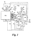
- this shows an engine 10 with a starter and an associated starter circuit 10a which is coupled through a friction clutch 14 with a multi-ratio transmission 12 via a transmission input shaft 15.
- fuel is supplied to the engine by a throttle 16 which includes a throttle valve 18 operated by an accelerator pedal 19.
- the invention is equally applicable to electronic or mechanical fuel injected petrol or diesel engines.
- the clutch 14 is actuated by a release fork 20 which is operated by a slave cylinder 22.
- the transmission is controlled by a ratio selector member in the form of a lever 24 which is connected with the transmission via a selector linkage 25 and which includes a load-sensing switch means 33 which detects forces applied to the lever 24 by the driver and produces a signal Vs indicating an intention to change the operative ratio of the transmission.
- An electronic control unit 36 controls the actuation of the clutch 14 via an hydraulic control 38 which controls the operation of slave cylinder 22.
- Control unit 36 receives signals Vs from selector lever 24 and signals Ve proportional to engine speed from engine speed sensor 26. Signals Vt from throttle valve position sensor 30 proportional to the current throttle opening and accelerator pedal position signals Va from an accelerator position sensor 19a are also fed to control unit 36.
- Control unit 36 also receives a ratio signal Vg from ratio position sensor 32 which corresponds to the transmission ratio currently engaged, signals Vc from slave cylinder position sensor 34, which varying with the position of the slave cylinder, and signals Vdp proportional to clutch driven plate speed from speed sensor 42 which actually senses the speed of the transmission input shaft 15 (which is equal to that of a driven plate 40 of the clutch 14).
- the driven plate speed sensor 42 acts in effect as a vehicle speed sensor and vice versa. Thus in some applications no drive plate speed sensor 42 is provided and this speed is calculated from the transmission ratio and the vehicle speed which is given by a separate sensor.
- a throttle control 37 is operated by the control unit 36 so that the throttle can be opened and closed independently of the accelerator pedal 19.
- a buzzer 50 is connected with control unit 36 to warn/indicate to the vehicle operator when certain vehicle operating conditions occur. In addition to or in place of buzzer 50 a flashing warning light (not shown) may be used.
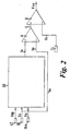
- Control unit 36 includes a reference signal generator 60 (see figure 2) which generates a reference signal Vr representative of a desired engine speed, This reference signal is compared in comparator A with the actual engine speed signal Ve from sensor 26 to produce an error signal E which is compared in comparator B with the clutch actuator position signal Vc from sensor 34 to provide a clutch engagement control signal Vce which control unit 36 outputs to hydraulic control 38. Operation of a control unit in this manner is described in more detail, for example, in the earlier European Patents 0038113 and 0043660 to which the reader should refer if further details are required.
- Co-pending UK Patent Application GB-A-2292591 includes a detailed description of the main reference signal generator 60 which detailed description is hereby incorporated in the present description.
- control unit 36 In addition to controlling the engagement and disengagement of clutch 14 the control unit 36 also controls the throttle setting via control 37 when its control logic indicates that an override of the throttle opening set by the driver's operation of the accelerator 19 is desirable. In some applications the throttle control 37 may be omitted.
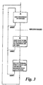
- the electronic control unit 36 includes a routine for determining the kiss-point of clutch 14 which is diagramatically illustrated in figure 3.
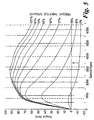
- the method is based on the realisation that, with the engine in the throttle closed overrun condition, the torque required to turn over a petrol engine remains relatively constant over a relatively wide range of engine speeds.
- Figure 5 shows a typical engine torque map where, for example, line X indicates that the negative torque remains substantially constant over a relatively wide speed range of say 2000 rpm to 6000 rpm. This negative torque is around 20% of the maximum torque developed by the engine. [It is believed that similar characteristics also apply to diesel engines].
- the clutch is engaged to a level of slippage sufficient for the vehicle to increase the speed of the engine to a substantially constant level the negative torque transmitted by the clutch also remains relatively constant at the above referred to engine turn-over level. If a measurement of the position of the clutch actuating mechanism is made when this negative torque is being transmitted it is then possible knowing the clutch engagement/torque characteristic to compute the kiss-point of the clutch from this measured position.
- FIG. 4 shows typical clutch engagement/torque characteristics where, clutch slip torque is plotted against clutch release bearing position.
- Curves T1, T2 and T3 show the characteristics of the same clutch at different times in its operating life and are therefore of the same curve form.
- Curve T1 shows the characteristic of a new unworn clutch
- T2 shows the characteristic of a half worn clutch
- T3 shows the characteristic of a fully worn clutch.
- Line Y in Figure 4 the so-called coast line, represents the steady state negative turn-over torque which is transmitted by the clutch during a kiss-point determination and is the line along which the clutch position measurements are taken during each kiss-point determination giving clutch release bearing position values (so-called coast points) B, E and G on curves T1, T3 and T2 respectively.
- Points D, F and H define the clutch release bearing positions at which the kiss-point occurs on curves T1, T3 and T2 respectively.
- the kiss-point determination method described below is implemented on 4th to 3rd downshifts in a five speed box as this is a shift where the torque reversed is less evident to the operator and passengers than shifts between lower gears and shifts from 4th to 3rd are more numerous than 5th to 4th shifts.
- the routine for kiss-point calibration is carried out during down changes from 4th to 3rd.
- the electronic control unit 36 checks that the throttle remains closed during the calibration routine and that the engine has been running for sufficient time since start-up for it and the clutch to have reached its normal operating temperature.
- the electronic control unit also estimates on a continual basis [using, for example, the mathematical model that the energy input into the pressure plate is equal to the integral of the product of clutch slip speed and clutch slip torque and also using standard conduction and convection heat transfer theory] the surface temperature of the clutch plate and only performs the calibration when the clutch surface temperature is within specified limits. If any of these conditions is exceeded, or if clutch slip speed does not remain above a lower limit, the calibration is aborted.
- the clutch is disengaged by the control unit 36 and the old gear is disengaged.
- the new gear is then engaged (see Block A) and engine speed and driven plate speeds are measured and a reference speed is set typically halfway between these measured speeds.
- Engagement of the clutch is then commenced by cylinder 22 until engagement just begins (see Block B) from where engagement continues under the control of unit 36 to raise the engine speed, for example, exponentially to the reference speed and then to hold the engine speed constant at the reference speed.
- clutch engagement is completed by raising the reference speed so that the engine speed is raised to the driven plate speed exponentially.
- Time limits are imposed on the periods during which the clutch is slipping to prevent prolonged clutch slippage.
- the amount by which (or rate at which) the kiss-point can change at each determination or the rate at which the kiss-point can be changed is preferably limited to eliminate transient effects. This can be achieved by filtering the individual kiss-point measurements and may be applied as a rate limit to the change.
- kiss-point determination method of the present invention has been described above as being performed during a downshift in the associated transmission it could be implemented in any circumstance in which the engine is operating in an overrun condition.
- the electronic control immediately prior to the electronic control means being de-activated at the end of a vehicle journey the electronic control stores a value of kiss-point position for use at the start of the next vehicle journey.
- This stored figure is related to the final actual kiss-point position computed prior to de-activation of the electronic control means and typically is the average of all the kiss-point positions computed during that journey.
- a 3-dimensional map of clamp load in relation to the release travel and wear could be stored as a sequence of data points. Measurement of the coast point as the wear progresses would enable the clamp load curve for a particular state of wear to be derived from the map and the corresponding kiss-point to be determined by interpolation.
Landscapes
- Engineering & Computer Science (AREA)
- Mechanical Engineering (AREA)
- Transportation (AREA)
- Chemical & Material Sciences (AREA)
- Combustion & Propulsion (AREA)
- Automation & Control Theory (AREA)
- Physics & Mathematics (AREA)
- Fluid Mechanics (AREA)
- General Engineering & Computer Science (AREA)
- Hydraulic Clutches, Magnetic Clutches, Fluid Clutches, And Fluid Joints (AREA)
Abstract
Claims (12)
- Procédé pour déterminer, pendant un processus de réenclenchement d'un embrayage, le point d'activation d'un embrayage (14) d'un véhicule comportant un disque d'embrayage (40) qui entraíne un véhicule à partir d'un moteur (10) par l'intermédiaire d'une transmission à rapports multiples (12), l'actionnement de l'embrayage (14) s'effectuant par l'intermédiaire d'un mécanisme (20, 22) d'actionnement de l'embrayage, sous la commande de moyens de commande électroniques (36), caractérisé en ce que le procédé comprend les étapes consistant à :vérifier que le papillon d'étranglement (18) du moteur (10) est fermé et que le véhicule est dans un état de décélération du moteur ;

- Procédé pour déterminer le point d'activation d'un embrayage (14) d'un véhicule comportant un disque d'embrayage (40) qui entraíne un véhicule à partir d'un moteur (10) par l'intermédiaire d'une transmission à rapports multiples (12), l'actionnement de l'embrayage (14) s'effectuant par l'intermédiaire d'un mécanisme (20, 22) d'actionnement de l'embrayage, sous la commande de moyens de commande électroniques (36), caractérisé en ce que ledit procédé comprend les étapes consistant à :
- Procédé selon la revendication 1 ou 2, caractérisé en ce que les moyens de commande électroniques (36) détectent la vitesse du moteur et la vitesse du disque entraíné (40) de l'embrayage (14) avant le réenclenchement, puis réenclenchent l'embrayage (14) pour entraíner le moteur (10) à une vitesse qui se trouve dans une relation prédéterminée par rapport auxdites vitesses détectées.
- Procédé selon les revendications 1 à 3, caractérisé en ce que le moteur (10) est entraíné à une vitesse se situant à mi-chemin entre la vitesse détectée du moteur et les vitesses détectées du disque entraíné.
- Procédé selon l'une quelconque des revendications 1 à 4, caractérisé en ce que pendant une détermination donnée du point d'activation, une série de mesures de la position du mécanisme d'actionnement de l'embrayage sont effectuées et ladite série de mesures sont comparées pour savoir si elles sont compatibles, et si elles sont suffisamment compatibles, ce qui indique un état stationnaire d'enclenchement de l'embrayage, elles sont utilisées pour une détermination du point d'activation.
- Procédé selon la revendication 5, caractérisé en ce qu'une limite de temps est réglée par les moyens de commande électroniques (36) pour effectuer les mesures de positions du mécanisme (20, 22) d'actionnement de l'embrayage de manière à empêcher un glissement prolongé de l'embrayage.
- Procédé selon l'une quelconque des revendications 1 à 6, caractérisé en ce qu'une détermination donnée du point d'activation est interrompue si le papillon des gaz (18) ne reste pas fermé ou si la vitesse du disque mené ne reste pas supérieure à une limite inférieure ou si la température de l'embrayage (14) ou une estimation de la température de l'embrayage (14) dépasse un niveau prédéterminé.
- Procédé selon l'une quelconque des revendications 1 à 7, caractérisé en ce qu'une étape préliminaire de contrôle du fait que le moteur (10) a fonctionné pendant un intervalle de temps suffisant pour garantir que la température normale de fonctionnement de l'embrayage a été atteinte, est incluse.
- Procédé selon l'une quelconque des revendications 1 à 8, caractérisé en ce que la quantité, dont la position mesurée du point d'activation peut être modifiée lors de chaque détermination, ou la vitesse avec laquelle le point d'activation peut être modifié, est limitée, afin de limiter des effets transitoires.
- Procédé selon l'une quelconque des revendications 1 à 9, caractérisé en ce que juste avant chaque désactivation des moyens de commande électroniques (36) à la fin de chaque déplacement du véhicule, les moyens de commande (36) mémorisent une valeur de la position du point d'activation associée à la position finale réelle du point d'activation calculée pendant ce déplacement spécifique.
- Procédé selon la revendication 10, caractérisé en ce que la valeur de la position du point d'activation mémorisée à la fin de chaque déplacement du véhicule est égale à la moyenne de l'ensemble des positions du point d'activation calculées pendant ce déplacement spécifique.
- Système de commande d'embrayage, qui inclut des moyens de commande électroniques, caractérisé en ce que les moyens de commande électroniques exécutent un programme pour déterminer le point d'activation de l'embrayage associé conformément au procédé selon l'une quelconque des revendications 1 à 11.
Applications Claiming Priority (3)
| Application Number | Priority Date | Filing Date | Title |
|---|---|---|---|
| GBGB9626527.7A GB9626527D0 (en) | 1996-12-20 | 1996-12-20 | Clutches |
| GB9626527 | 1996-12-20 | ||
| PCT/GB1997/003497 WO1998028162A1 (fr) | 1996-12-20 | 1997-12-19 | Systeme de commande d'embrayage |
Publications (2)
| Publication Number | Publication Date |
|---|---|
| EP0883509A1 EP0883509A1 (fr) | 1998-12-16 |
| EP0883509B1 true EP0883509B1 (fr) | 2002-03-20 |
Family
ID=10804778
Family Applications (1)
| Application Number | Title | Priority Date | Filing Date |
|---|---|---|---|
| EP97950287A Expired - Lifetime EP0883509B1 (fr) | 1996-12-20 | 1997-12-19 | Systeme de commande d'embrayage |
Country Status (8)
| Country | Link |
|---|---|
| US (1) | US6086514A (fr) |
| EP (1) | EP0883509B1 (fr) |
| JP (1) | JP2001501289A (fr) |
| KR (1) | KR100572261B1 (fr) |
| AU (1) | AU5329898A (fr) |
| DE (1) | DE69711170T2 (fr) |
| GB (2) | GB9626527D0 (fr) |
| WO (1) | WO1998028162A1 (fr) |
Cited By (1)
| Publication number | Priority date | Publication date | Assignee | Title |
|---|---|---|---|---|
| DE102005021711A1 (de) * | 2005-05-11 | 2007-02-08 | Zf Friedrichshafen Ag | Verfahren zum Bestimmen des Anlegepunktes einer automatisch betätigten Reibungskupplung |
Families Citing this family (41)
| Publication number | Priority date | Publication date | Assignee | Title |
|---|---|---|---|---|
| JP3598847B2 (ja) * | 1998-10-28 | 2004-12-08 | いすゞ自動車株式会社 | クラッチ断接装置 |
| DE10080639B4 (de) * | 1999-03-15 | 2017-03-02 | Schaeffler Technologies AG & Co. KG | Kupplungssteuervorrichtung zur automatischen Betätigung einer Kupplung während des Anfahrens |
| DE19951527C1 (de) * | 1999-10-26 | 2001-06-13 | Siemens Ag | Steuerung für eine automatisch betätigte Kupplung eines Kraftfahrzeugs und Verfahren zum Steuern einer automatisch betätigten Kupplung |
| FR2819564B1 (fr) | 2001-01-17 | 2003-03-14 | Renault | Procede d'etablissement de la courbe d'embrayage d'un organe d'embrayage monte entre un moteur a combustion interne et une boite de vitesses d'un vehicule automobile propluse par ce moteur |
| WO2002084136A1 (fr) * | 2001-04-11 | 2002-10-24 | Luk Lamellen Und Kupplungsbau Beteiligungs Kg | Procede et dispositif pour detecter le point de contact d'un embrayage |
| US6494810B1 (en) | 2001-05-30 | 2002-12-17 | Eaton Corporation | Clutch calibration and control |
| FR2828450B1 (fr) | 2001-08-07 | 2003-10-03 | Renault | Dispositif d'assistance au demarrage en cote pour vehicule automobile |
| JP3712193B2 (ja) * | 2001-12-10 | 2005-11-02 | 本田技研工業株式会社 | 動力伝達装置における摩擦係合要素の係合制御方法 |
| FR2833667B1 (fr) | 2001-12-17 | 2004-04-09 | Renault | Systeme de diagnostic de l'usure de l'embrayage d'un vehicule automobile |
| JP4542307B2 (ja) * | 2002-10-18 | 2010-09-15 | アイシン精機株式会社 | クラッチ制御装置 |
| EP1491787B1 (fr) * | 2003-06-23 | 2006-09-27 | LuK Lamellen und Kupplungsbau Beteiligungs KG | Procédé et dispositif pour contrôler un embrayage |
| DE102004007160A1 (de) * | 2004-02-12 | 2005-08-25 | Volkswagen Ag | Verfahren zur Verhinderung von Lastwechselschlägen bei einem Kraftfahrzeug |
| US7912613B2 (en) * | 2004-07-01 | 2011-03-22 | Yamaha Hatsudoki Kabushiki Kaisha | Riding type vehicle |
| CN100451372C (zh) * | 2006-01-05 | 2009-01-14 | 财团法人工业技术研究院 | 定义离合器接触点及扭力特性曲线的方法 |
| ATE491098T1 (de) | 2006-03-30 | 2010-12-15 | Ind Tech Res Inst | Verfahren um einen kupplungspunkt und eine diesbezügliche momentenkennlinie zu definieren |
| DE102007002343A1 (de) * | 2007-01-16 | 2008-07-17 | Zf Friedrichshafen Ag | Verfahren zur dynamischen Ermittlung eines Kupplungs-Ruhepunktes |
| DE602007005240D1 (de) * | 2007-07-05 | 2010-04-22 | Magneti Marelli Spa | Verfahren zur Steuerung eines mit einer mechanischen Servogetriebe ausgerüsteten Fahrzeugs |
| DE102007057081B4 (de) * | 2007-11-21 | 2009-12-24 | Bayerische Motoren Werke Aktiengesellschaft | Verfahren zum Einstellen eines Einrückpunktes einer Reibkupplung |
| DE102008000770A1 (de) * | 2008-03-19 | 2009-09-24 | Robert Bosch Gmbh | Verfahren und Vorrichtung zum Schließen einer Kupplung |
| US8577570B2 (en) * | 2009-04-17 | 2013-11-05 | Honda Motor Co., Ltd. | Touch point calibration method for a motor vehicle |
| DE102010024941A1 (de) * | 2009-07-16 | 2011-01-20 | Luk Lamellen Und Kupplungsbau Beteiligungs Kg | Kupplungstastpunkte |
| FR2950303B1 (fr) | 2009-09-24 | 2011-10-28 | Peugeot Citroen Automobiles Sa | Procede d'apprentisage du point de lechage d'un embrayage par la courbe caracteristique de l'embrayage pour un vehicule hybride |
| DE102009053885B4 (de) * | 2009-11-20 | 2015-10-29 | Getrag Getriebe- Und Zahnradfabrik Hermann Hagenmeyer Gmbh & Cie Kg | Verfahren zur Kisspointadaption |
| DE102010039172B4 (de) * | 2010-08-11 | 2023-12-07 | Zf Friedrichshafen Ag | Verfahren zur Ermittlung eines Anlegebetätigungsdruckwertes eines reibschlüssigen Schaltelements |
| EP2458249B1 (fr) * | 2010-11-25 | 2017-01-04 | Transmisiones y Equipos Mecánicos, S.A. de C.V. | Procédé de contrôle d'un double embrayage dans une transmission de véhicule, et système de commande d'embrayage pour contrôler un double embrayage |
| SE535679C2 (sv) * | 2011-03-14 | 2012-11-06 | Scania Cv Ab | Förfarande och system vid bestämning av en kontaktpunkt för en koppling |
| JP2014035069A (ja) * | 2012-08-10 | 2014-02-24 | Yamaha Motor Co Ltd | 車両 |
| DE102013220324A1 (de) * | 2012-10-31 | 2014-04-30 | Schaeffler Technologies Gmbh & Co. Kg | Verfahren zur Betätigung einer Reibungskupplung |
| KR101355620B1 (ko) * | 2012-11-09 | 2014-01-27 | 기아자동차주식회사 | 클러치의 터치포인트 탐색 방법 |
| KR101406625B1 (ko) | 2012-11-09 | 2014-06-11 | 기아자동차주식회사 | 클러치의 터치포인트 탐색 방법 |
| US9127729B2 (en) | 2013-08-16 | 2015-09-08 | GM Global Technology Operations LLC | Method of learning a clutch kiss point for a clutch of a dual clutch transmission |
| KR101470209B1 (ko) * | 2013-09-17 | 2014-12-05 | 현대자동차주식회사 | 하이브리드 차량용 클러치 제어방법 및 장치 |
| US10087998B2 (en) * | 2014-11-19 | 2018-10-02 | Dana Automotive Systems Group, Llc | Method to control clutch force in a clutch pack |
| CN107110238B (zh) * | 2014-12-11 | 2019-12-24 | Pt技术有限公司 | 单式封装的柴油发动机离合器组合件 |
| KR101755851B1 (ko) | 2015-10-01 | 2017-07-10 | 현대자동차주식회사 | 차량용 클러치의 터치포인트 학습방법 |
| KR101916545B1 (ko) | 2016-12-15 | 2018-11-07 | 현대자동차주식회사 | 클러치의 터치 포인트 학습 장치 및 방법 |
| KR102461506B1 (ko) * | 2017-09-25 | 2022-11-02 | 현대자동차주식회사 | Amt차량의 클러치 제어방법 |
| CN111433478B (zh) * | 2017-12-13 | 2021-10-19 | Gkn汽车有限公司 | 操作离合器装置的方法 |
| DE102020104153A1 (de) | 2020-02-18 | 2021-08-19 | Bayerische Motoren Werke Aktiengesellschaft | Verfahren zum Nachführen eines Arbeitspunktes einer Kupplung sowie Kraftwagen mit einer Kupplung |
| CN114215861B (zh) * | 2021-12-13 | 2023-09-22 | 义乌吉利自动变速器有限公司 | 离合器智能调整方法、装置、设备与存储介质 |
| US11685258B1 (en) * | 2022-06-27 | 2023-06-27 | Ford Global Technologies, Llc | System and method to reduce transfer clutch overheating |
Family Cites Families (23)
| Publication number | Priority date | Publication date | Assignee | Title |
|---|---|---|---|---|
| AU548876B2 (en) | 1980-02-18 | 1986-01-09 | Automotive Products Ltd. | Standing-start clutch control |
| DE3174453D1 (en) | 1980-07-08 | 1986-05-28 | Automotive Prod Plc | Clutch control system |
| AU552105B2 (en) * | 1981-02-24 | 1986-05-22 | Automotive Products Ltd. | Clutch control system |
| AU1725283A (en) | 1982-08-11 | 1984-02-16 | Automotive Products Plc | Clutch control system |
| US4646891A (en) * | 1985-01-31 | 1987-03-03 | Eaton Corporation | Automatic clutch control |
| JPH06104427B2 (ja) * | 1985-07-05 | 1994-12-21 | 富士通株式会社 | 自動変速機付車両のインチング制御方法 |
| US4711141A (en) * | 1986-04-30 | 1987-12-08 | Eaton Corporation | Method for controlling AMT system including after transmission gear change clutch and fuel control |
| JP2636283B2 (ja) * | 1987-12-11 | 1997-07-30 | いすゞ自動車株式会社 | 自動クラッチ制御装置 |
| US4899858A (en) * | 1989-03-02 | 1990-02-13 | Eaton Corporation | Method and control system for updating of control parameter value indicative of master clutch point of incipient engagement |
| US5184301A (en) * | 1990-11-27 | 1993-02-02 | Navistar International Transportation Corp. | Automotive vehicle microprocessor control having clutch priority engine speed control |
| GB9101164D0 (en) | 1991-01-18 | 1991-02-27 | Automotive Prod Plc | Clutch control system |
| DE4134669C2 (de) * | 1991-10-19 | 1998-07-02 | Mannesmann Sachs Ag | Anordnung zur Erfassung der Stellung beginnender Drehmomentübertragung einer Kraftfahrzeugkupplung |
| US5337868A (en) * | 1992-01-02 | 1994-08-16 | Eaton Corporation | Touch point identification for automatic clutch controller |
| US5332074A (en) * | 1992-01-06 | 1994-07-26 | Eaton Corporation | Incipient clutch control system |
| US5314050A (en) * | 1992-12-09 | 1994-05-24 | Eaton Corporation | Clutch mode control logic |
| US5337874A (en) * | 1993-03-19 | 1994-08-16 | Eaton Corporation | Method/system for determining clutch touch point |
| US5383823A (en) * | 1993-06-10 | 1995-01-24 | Eaton Corporation | Clutch control |
| US5411124A (en) * | 1993-08-26 | 1995-05-02 | Eaton Corporation | Method and apparatus for determining clutch touch point |
| GB9402730D0 (en) | 1994-02-12 | 1994-04-06 | Automotive Products Plc | Clutch control system |
| US5439428A (en) * | 1994-02-22 | 1995-08-08 | Eaton Corporation | Method and apparatus for robust automatic clutch control with pid regulation |
| US5634867A (en) * | 1994-09-19 | 1997-06-03 | Eaton Corporation | Main clutch reengagement control for a double clutch downshift |
| GB9504681D0 (en) * | 1995-03-08 | 1995-04-26 | Eaton Corp | Improvements in vehicle control |
| NO314174B1 (no) * | 1995-12-18 | 2003-02-10 | Luk Getriebe Systeme Gmbh | Motorkjöretöy |
-
1996
- 1996-12-20 GB GBGB9626527.7A patent/GB9626527D0/en active Pending
-
1997
- 1997-12-19 DE DE69711170T patent/DE69711170T2/de not_active Expired - Lifetime
- 1997-12-19 US US09/117,855 patent/US6086514A/en not_active Expired - Fee Related
- 1997-12-19 GB GB9816927A patent/GB2324584B/en not_active Revoked
- 1997-12-19 EP EP97950287A patent/EP0883509B1/fr not_active Expired - Lifetime
- 1997-12-19 WO PCT/GB1997/003497 patent/WO1998028162A1/fr not_active Ceased
- 1997-12-19 JP JP10528534A patent/JP2001501289A/ja active Pending
- 1997-12-19 AU AU53298/98A patent/AU5329898A/en not_active Abandoned
-
1998
- 1998-08-19 KR KR1019980706448A patent/KR100572261B1/ko not_active Expired - Fee Related
Cited By (1)
| Publication number | Priority date | Publication date | Assignee | Title |
|---|---|---|---|---|
| DE102005021711A1 (de) * | 2005-05-11 | 2007-02-08 | Zf Friedrichshafen Ag | Verfahren zum Bestimmen des Anlegepunktes einer automatisch betätigten Reibungskupplung |
Also Published As
| Publication number | Publication date |
|---|---|
| KR100572261B1 (ko) | 2007-03-02 |
| WO1998028162A1 (fr) | 1998-07-02 |
| AU5329898A (en) | 1998-07-17 |
| DE69711170D1 (de) | 2002-04-25 |
| GB9816927D0 (en) | 1998-09-30 |
| DE69711170T2 (de) | 2002-11-14 |
| GB2324584A (en) | 1998-10-28 |
| KR19990087062A (ko) | 1999-12-15 |
| EP0883509A1 (fr) | 1998-12-16 |
| US6086514A (en) | 2000-07-11 |
| GB2324584B (en) | 2000-09-06 |
| JP2001501289A (ja) | 2001-01-30 |
| GB9626527D0 (en) | 1997-02-05 |
Similar Documents
| Publication | Publication Date | Title |
|---|---|---|
| EP0883509B1 (fr) | Systeme de commande d'embrayage | |
| EP0616142B1 (fr) | Système pour détection du point du contact d'un embrayage | |
| AU672307B2 (en) | Touch point identification algorithm for automatic clutch controller | |
| US4873637A (en) | Control for vehicle start from stop operation | |
| US6482123B2 (en) | Method of controlling heat buildup in a clutch | |
| EP0385629B1 (fr) | Méthode et système d'actualisation de la valeur de commande indiquant le point de commencement d'engagement de l'embrayage principal | |
| JP2873348B2 (ja) | 自動クラッチ式変速機の制御装置 | |
| EP0328299B1 (fr) | Commande du démarrage dans un système de transmission mécanique automatique, à partir de l'arrêt | |
| US4646891A (en) | Automatic clutch control | |
| US6602161B2 (en) | Arrangement for operating the clutch in the power train of a motor vehicle | |
| CN1083355C (zh) | 车辆传动装置 | |
| AU663036B2 (en) | Clutch mode control logic | |
| EP0696341B1 (fr) | Systeme de commande d'embrayage | |
| KR100376593B1 (ko) | 클러치제어시스템 | |
| AU689681B2 (en) | Integrated engine and transmission control system | |
| GB2097074A (en) | Transmission control system in a vehicle | |
| JPH1071875A (ja) | 自動車並びに該自動車の適用のための方法 | |
| EP0244131B1 (fr) | Procédé pour commander une transmission mécanique automatique, y compris la commande pour l'embrayage et le carburant suivant un changement de vitesse | |
| US6440039B1 (en) | Torque-transmitting system | |
| JPH0620842B2 (ja) | 車両の発進制御装置 |
Legal Events
| Date | Code | Title | Description |
|---|---|---|---|
| PUAI | Public reference made under article 153(3) epc to a published international application that has entered the european phase |
Free format text: ORIGINAL CODE: 0009012 |
|
| AK | Designated contracting states |
Kind code of ref document: A1 Designated state(s): DE ES FR GB IT |
|
| 17P | Request for examination filed |
Effective date: 19981216 |
|
| RAP1 | Party data changed (applicant data changed or rights of an application transferred) |
Owner name: LUK LEAMINGTON LIMITED |
|
| 17Q | First examination report despatched |
Effective date: 20000724 |
|
| GRAG | Despatch of communication of intention to grant |
Free format text: ORIGINAL CODE: EPIDOS AGRA |
|
| GRAG | Despatch of communication of intention to grant |
Free format text: ORIGINAL CODE: EPIDOS AGRA |
|
| GRAG | Despatch of communication of intention to grant |
Free format text: ORIGINAL CODE: EPIDOS AGRA |
|
| GRAH | Despatch of communication of intention to grant a patent |
Free format text: ORIGINAL CODE: EPIDOS IGRA |
|
| GRAH | Despatch of communication of intention to grant a patent |
Free format text: ORIGINAL CODE: EPIDOS IGRA |
|
| REG | Reference to a national code |
Ref country code: GB Ref legal event code: IF02 |
|
| GRAA | (expected) grant |
Free format text: ORIGINAL CODE: 0009210 |
|
| AK | Designated contracting states |
Kind code of ref document: B1 Designated state(s): DE ES FR GB IT |
|
| REF | Corresponds to: |
Ref document number: 69711170 Country of ref document: DE Date of ref document: 20020425 |
|
| ET | Fr: translation filed | ||
| PG25 | Lapsed in a contracting state [announced via postgrant information from national office to epo] |
Ref country code: ES Free format text: LAPSE BECAUSE OF FAILURE TO SUBMIT A TRANSLATION OF THE DESCRIPTION OR TO PAY THE FEE WITHIN THE PRESCRIBED TIME-LIMIT Effective date: 20020925 |
|
| PLBE | No opposition filed within time limit |
Free format text: ORIGINAL CODE: 0009261 |
|
| STAA | Information on the status of an ep patent application or granted ep patent |
Free format text: STATUS: NO OPPOSITION FILED WITHIN TIME LIMIT |
|
| 26N | No opposition filed |
Effective date: 20021223 |
|
| PGFP | Annual fee paid to national office [announced via postgrant information from national office to epo] |
Ref country code: IT Payment date: 20071220 Year of fee payment: 11 |
|
| PGFP | Annual fee paid to national office [announced via postgrant information from national office to epo] |
Ref country code: GB Payment date: 20081217 Year of fee payment: 12 |
|
| PGFP | Annual fee paid to national office [announced via postgrant information from national office to epo] |
Ref country code: FR Payment date: 20100106 Year of fee payment: 13 |
|
| PGFP | Annual fee paid to national office [announced via postgrant information from national office to epo] |
Ref country code: DE Payment date: 20091229 Year of fee payment: 13 |
|
| GBPC | Gb: european patent ceased through non-payment of renewal fee |
Effective date: 20091219 |
|
| PG25 | Lapsed in a contracting state [announced via postgrant information from national office to epo] |
Ref country code: GB Free format text: LAPSE BECAUSE OF NON-PAYMENT OF DUE FEES Effective date: 20091219 |
|
| REG | Reference to a national code |
Ref country code: FR Ref legal event code: ST Effective date: 20110831 |
|
| PG25 | Lapsed in a contracting state [announced via postgrant information from national office to epo] |
Ref country code: FR Free format text: LAPSE BECAUSE OF NON-PAYMENT OF DUE FEES Effective date: 20110103 |
|
| REG | Reference to a national code |
Ref country code: DE Ref legal event code: R119 Ref document number: 69711170 Country of ref document: DE Effective date: 20110701 |
|
| PG25 | Lapsed in a contracting state [announced via postgrant information from national office to epo] |
Ref country code: DE Free format text: LAPSE BECAUSE OF NON-PAYMENT OF DUE FEES Effective date: 20110701 |
|
| PG25 | Lapsed in a contracting state [announced via postgrant information from national office to epo] |
Ref country code: IT Free format text: LAPSE BECAUSE OF NON-PAYMENT OF DUE FEES Effective date: 20081219 |