EP0883703B1 - Procede de filage ou de retordage sur broche et unite de travail pour la mise en oeuvre du procede - Google Patents
Procede de filage ou de retordage sur broche et unite de travail pour la mise en oeuvre du procede Download PDFInfo
- Publication number
- EP0883703B1 EP0883703B1 EP97904336A EP97904336A EP0883703B1 EP 0883703 B1 EP0883703 B1 EP 0883703B1 EP 97904336 A EP97904336 A EP 97904336A EP 97904336 A EP97904336 A EP 97904336A EP 0883703 B1 EP0883703 B1 EP 0883703B1
- Authority
- EP
- European Patent Office
- Prior art keywords
- spindle
- yarn
- open loop
- working surface
- balloon limiter
- Prior art date
- Legal status (The legal status is an assumption and is not a legal conclusion. Google has not performed a legal analysis and makes no representation as to the accuracy of the status listed.)
- Expired - Lifetime
Links
- 238000009987 spinning Methods 0.000 title claims description 70
- 238000000034 method Methods 0.000 title claims description 20
- 238000004804 winding Methods 0.000 claims description 82
- 230000000670 limiting effect Effects 0.000 claims description 58
- 230000000694 effects Effects 0.000 claims description 19
- 238000004140 cleaning Methods 0.000 claims description 8
- 238000009423 ventilation Methods 0.000 claims description 8
- 230000002093 peripheral effect Effects 0.000 claims description 6
- 230000007704 transition Effects 0.000 claims description 6
- 230000009471 action Effects 0.000 claims description 4
- 230000015572 biosynthetic process Effects 0.000 description 17
- 239000000835 fiber Substances 0.000 description 15
- 238000004519 manufacturing process Methods 0.000 description 8
- 230000036961 partial effect Effects 0.000 description 8
- 230000003111 delayed effect Effects 0.000 description 6
- 230000008569 process Effects 0.000 description 6
- 238000010276 construction Methods 0.000 description 5
- 230000002829 reductive effect Effects 0.000 description 5
- 241000673677 Viburnum lantana Species 0.000 description 4
- 238000003860 storage Methods 0.000 description 4
- 230000008901 benefit Effects 0.000 description 3
- 230000002349 favourable effect Effects 0.000 description 3
- 239000012535 impurity Substances 0.000 description 3
- 239000002655 kraft paper Substances 0.000 description 3
- 239000000463 material Substances 0.000 description 3
- 229920000742 Cotton Polymers 0.000 description 2
- 241000209035 Ilex Species 0.000 description 2
- 230000005540 biological transmission Effects 0.000 description 2
- 238000010924 continuous production Methods 0.000 description 2
- 230000007423 decrease Effects 0.000 description 2
- 230000008092 positive effect Effects 0.000 description 2
- 230000009467 reduction Effects 0.000 description 2
- 238000007378 ring spinning Methods 0.000 description 2
- 238000007493 shaping process Methods 0.000 description 2
- 238000004904 shortening Methods 0.000 description 2
- 206010020112 Hirsutism Diseases 0.000 description 1
- 230000004888 barrier function Effects 0.000 description 1
- 239000002131 composite material Substances 0.000 description 1
- 239000000428 dust Substances 0.000 description 1
- 239000002657 fibrous material Substances 0.000 description 1
- 238000003780 insertion Methods 0.000 description 1
- 230000037431 insertion Effects 0.000 description 1
- 229910001092 metal group alloy Inorganic materials 0.000 description 1
- 230000000704 physical effect Effects 0.000 description 1
- 230000002441 reversible effect Effects 0.000 description 1
- 238000005096 rolling process Methods 0.000 description 1
- 239000007787 solid Substances 0.000 description 1
- 230000003068 static effect Effects 0.000 description 1
- 230000001360 synchronised effect Effects 0.000 description 1
- 238000011144 upstream manufacturing Methods 0.000 description 1
Images






Classifications
-
- D—TEXTILES; PAPER
- D01—NATURAL OR MAN-MADE THREADS OR FIBRES; SPINNING
- D01H—SPINNING OR TWISTING
- D01H1/00—Spinning or twisting machines in which the product is wound-up continuously
- D01H1/14—Details
- D01H1/42—Guards or protectors for yarns or threads, e.g. separator plates, anti-ballooning devices
- D01H1/427—Anti-ballooning cylinders, e.g. for two-for-one twist machine
-
- D—TEXTILES; PAPER
- D01—NATURAL OR MAN-MADE THREADS OR FIBRES; SPINNING
- D01H—SPINNING OR TWISTING
- D01H1/00—Spinning or twisting machines in which the product is wound-up continuously
- D01H1/06—Spinning or twisting machines in which the product is wound-up continuously cap type
Definitions
- the invention relates to the spindle spinning or spindle twisting process, that on a spinning device with a feed device for the fiber structure, with a driven Spindle for the sleeve and with one coaxial with the spindle arranged, also driven balloon limiter, the on the inside a work surface for contact with the yarn is carried out, and a spinning device for Execution of the procedure.
- the invention has for its object a method of the type mentioned and the spinning device for implementation of the process, which reliably all out the use of the known yarn strength control before Eliminate yarn winding on the core of the disadvantages and thereby the production of a ring spinning or ring twist yarn of high quality even at extremely high production speeds enable.
- that the rotating open loop is radial during operation is limited.
- the size of the rotating open loop i.e. the removal of their Backbend reduced from the axis of rotation of the spindle be, so that the production of a quality yarn even under relatively small space requirements is made possible.
- the spinning device for performing the method contains a feeding device for the fiber structure, one driven spindle for the sleeve and one with the spindle balloon limiter also coaxial, also driven, which on the inside is a work surface for has contact with the yarn.
- a circumferential contact point on the work surface for the transition of the yarn from this work surface is placed directly on the sleeve, with the yarn through the effects of centrifugal force in the form of a rotating open loop is formed, any location the work surface, which is at a greater distance from the The end of the balloon limiter entry as the circumferential contact point located at the greater radial distance from the Axis of rotation of the spindle arranged as this circumferential contact point is.
- This spinning device works according to the method according to the invention, with all previous limitations in the field the so-called yarn force control before winding up the yarn the sleeve is eliminated. This enables different To produce yarn types that are at least as good as the so-called Ring yarn are, and high production speeds too to reach.
- Fig. 1 is the complete spinning device for spindle spinning, arranged on the frame 1 of the spinning machine, the basic components of which form the feed device 2 of the fiber structure and the turning and winding device 3 with an upstream control point of the beginning of the formation of the yarn balloon.
- the feed device 2 is embodied in the spinning device for the spindle spinning by the usual drafting device 4 with the exit rollers 5 .
- the delay device 4 is known in various designs from spindle or nozzle spinning and from other spinning systems, so that it is not described in more detail.
- the purpose of the drafting device is to process the sliver so that a fiber tape is available at the exit from the drafting device, the length of which corresponds to the length of the spun yarn P.
- a roving spool 8 is attached to the holder 6 , adjustable on the vertical rod 7 , from which the roving 9 unwinds, which is fed into the preference device 4 via a guide 10 .
- the dashed lines indicate an alternative arrangement for supplying the drafting device 4 with the fiber sliver 11 drawn from a can 12 .
- the rotating and winding device 3 (FIGS. 1, 2) consists of the spindle 13 and the balloon limiter 14 arranged concentrically to the spindle 13 .
- the drafting device 4 is assigned a control point 15 at the beginning of the formation of the yarn balloon 16 of the yarn P formed. This control point is attached to the surface of at least one of the exit rollers 5 of the drafting device 4 as a control contact of the yarn with the corresponding exit roller or the exit rollers 5 .
- the arrangement of the control body 15 enables the region of the nip of the exit rollers 5 that the yarn P is formed, without common yarn guide from the delay means 4, directly into the turning and winding device 3, comes out.
- the drive electric motor 18 of the spindle 13 is attached to the spindle bank 19 , which is displaceably attached to the vertical guide rod 21 by means of the bush 20 , which is part of the known, not shown device for causing the program-controlled, vertical up and down movement of the spindle 13 in the sense of the double file 22 is.
- the spindle 13 can also be operated with other conventional drive means, for example with a belt transmission.
- a sleeve 23 (FIG. 2) for the yarn winding 24 is placed on the spindle 13 .
- the program of the movement of the spindle bank 19 in the sense of the double file 22 is determined by the choice of the yarn winding 24 .
- the spindle is immovably attached to the frame 1 , while the balloon limiter 14 executes a valuable movement along the spindle 13 .
- the balloon limiter 14 is formed, for example, from a hollow cylinder 25 which has a funnel-shaped mouth 26 in the form of a radial flange 27 on the side facing away from the control point 15 .
- the balloon limiter 14 respectively.
- the funnel-shaped mouth 26 merges into a limiting ring 28 which is concentric with the axis 17 of the spindle 13 and which carries on its inside a limiting wall 29 , advantageously with a concave profile.
- This boundary wall 29 merges into the side wall 30 , which runs essentially parallel to the radial flange 27 and is terminated with a short flange 31 , which opens the opening for the passage of the spindle 13 and the sleeve 23 with the yarn winding 24 (FIG. 2 , 3).
- the cylinder 25 is rotatably mounted on aerostatic or roller bearings 32 in a two-part bushing 33 , the flange 34 of which is fastened to the bench 35 by means not shown, which is fastened to the frame 1 of the spinning device by means not shown.
- the balloon limiter 14 which passes through the concentric opening 36 of the bench 35 , is driven by the belt 37 by the electric motor 38 attached to the frame 1 (FIG. 1).
- the two-part sleeve 33 has an inner radial groove 39 with a radial opening (not shown) for the entry and exit of the belt 37.
- the rotation of the balloon limiter 14 in the direction of the arrow 40 is the same as the rotation of the spindle 13 in the direction of the arrow 41 .
- the cylinder 25 can optionally be manufactured as a rotor of the drive electric motor or it can be driven by a driven friction roller or the like. are driven.
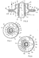
- the limiting ring 28 , the funnel-shaped mouth 26 of the balloon limiter 14 and the side wall 30 delimit the orientation cavity 42 , which has the shape of a radial gap 43 (FIG. 3). The purpose of the orientation cavity 42 will be explained.
- the balloon restrictor 14 has an inner working surface 44 for contact with the yarn P that is realized between the inlet end 45 and the outlet end 46 (FIG. 2).
- the working surface 44 is the part of the surface of the cavity of the balloon limiter 14 against which the yarn formed is pressed by the centrifugal force and with which this yarn is carried.
- the outlet end 46 is arranged on the working surface 44 in the largest diameter of the boundary wall 29 (FIGS. 2, 3).
- Other shapes of the working surface 44 in the cylindrical part of the balloon limiter 14 are also suitable for the purpose of the invention.
- the work surface is shaped in the middle part into a sleeve, which widens conically in the direction of the inlet end on one side and towards the outlet end on the other side.
- the cylinder 25 is advantageously thin-walled and made of a light metal alloy or a composite. It is desirable that the working surface 44 have a layer of a suitable material to ensure low friction against the yarn and that it have a high wear resistance.
- the working surface can optionally be provided with a groove or a rib to form ventilation effects to reduce the frictional properties compared to the thread, which expediently reduce the direct contact of the thread with the working surface of the balloon limiter, but on the condition that the working surface is still able , take the yarn that it passes through with the friction.
- a circumferential contact point 47 for the transition of the yarn P from the working surface 44 into the rotating open loop 48 , is delimited, which is formed by the centrifugal force, as will be explained further.
- the circumferential contact point 47 is arranged in the transition region of the cavity from the cylinder 25 into the funnel-shaped mouth 26 , which forms the smallest diameter of the working surface 44 of the balloon limiter 14 .
- this initial contact point can be arranged in the last smallest diameter of the work surface 44 , in the direction of movement of the yarn P through the balloon limiter 14 .
- the radial distance A of the circumferential contact point 47 from the axis 17 of the spindle 13 is less than the radial distance B of the boundary wall 29 of the limiting ring 28 from the axis 17 of the spindle 13 , this radial distance B being equal to the radial distance C of the outlet end 46 from the Axis 11 of the spindle 13 is (Fig. 3, 4).
- the limiting ring 28 is shown with radial or tangential ventilation openings 49 (because of a simplification of the figure, only one ventilation opening 49 is shown), the purpose of which will be explained below.
- the sense of rotation of the spindle 13 and the balloon limiter 14 according to the arrows 40 , 41 is basically the same.
- the balloon limiter 14 merges into the limiting ring 28 .
- the balloon limiter 14 in the direction of movement of the yarn P through the balloon limiter 14 , is followed by a positionally stable and concentric with the spindle 13 limiting ring 28 .
- the word "connects" means that the limiting ring 28 is either fixedly connected to the balloon limiter 14 , as can be seen in FIGS. 1 to 3, or arranged independently, either fixedly or movably with its own drive, as will be explained further is.
- the spinning device according to FIGS. 1 to 4 works as follows:
- a fiber ribbon with the length weight of the resulting yarn emerges from the drafting device 4 , into which the roving 9 unwound from the roving bobbin 8 is fed.
- the fiber structure is solidified immediately after the nip point of the exit rollers 5 by the drafting device 4 by means of rotations which the fiber structure on the one hand by the effect of the rotation of the beginning of the yarn P on the sleeve 23 by the revolutions (n v ) of the spindle 13 and on the other hand by additional rotations , caused by the revolutions (n pp ) of the working surface 44 over which the yarn P carried by it moves.
- a consequence of the rotational relationship of the spindle 13 and the balloon limiter 14 is a higher twist in the yarn P , in its section between the nip of the exit rollers 5 and the exit end 46 of the work surface 44 (Fig. 2).
- the beginning of the yarn section mentioned is not directly in the nip of the exit rollers 5 , because a fiber ribbon emerges from this nip, which is drawn by rotation into the so-called twist triangle, the apex of which is the actual location of the beginning of the yarn balloon formed. To simplify matters, this small part of the length can be neglected in the yarn section mentioned.
- the rotating yarn expands and enters the rotating open loop 48 due to the effect of the balance between the centrifugal force caused by the weight of the yarn, the reaction friction force of the yarn as it moves over the working surface 44 and the reaction winding force into the radial gap 43 , in which it is radially delimited by the boundary wall 29 , over which the back bend 50 of the rotating open loop 48 moves.
- the circumferential contact point 47 just mentioned is delimited by the beginning of the rotating open loop 48 .
- the expansion respectively. Shaping of the rotating open loop 48 is also influenced to a certain extent by the pneumatic forces that act in the formation point of the loop. Since these pneumatic forces are insignificant for the formation of the rotating open loop, they are not explained in more detail in the description.
- the magnitude of the centrifugal force is influenced by the radial distance D of the back bend 50 of the rotating open loop 48 from the axis 17 of the spindle 13 , which is greater than the radial distance A , by the action of which the rotating open loop 48 is formed .
- orientation cavity 42 especially the radial gap 43 , is to orient the position of the rotating open loop 48 in accordance with the thread winding on the sleeve 23 .
- the rotating open loop 48 which consumes the fiber structure provided by the draft device 4 and to expand more and more and their reverse bend 50 away from the axis 17 of the spindle 13 .
- the rotating open loop 48 and the spindle 13 rotate in the same revolutions, whereby a radial slip occurs between the yarn P and the work surface 44 , which compensates for the difference in revolutions between the spindle 13 and the work surface 44 .
- the frictional forces which cause the yarn P to wind up on the sleeve 23 increase so that the ratio n pp > n v the rotating open loop 48x drawn by dashed lines overtakes the spindle 13 in its rotation and conversely with the ratio n pp ⁇ n v the rotating open loop 48y also drawn by the dashed lines is delayed in its rotation with respect to the spindle 13 (FIG. 4).
- the yarn P is wound onto the sleeve 23 and the slip between the yarn and the working surface 44 is reduced.
- the spinning process is characterized by a very rapid alternation of the two phases mentioned, which continues into the continuous process in which the two phases penetrate each other.
- n pp > n v and n pp ⁇ n v it is necessary that the tensile force in the yarn has a certain value, and not too little, where the refilling of the rotating open loop 48 could not take place with yarn, but also not too great that the tensile stress in the yarn would not cause any yarn stretching and therefore no loss of the yarn elongation required for the subsequent processing stages.
- the rotating open loop 48 itself forms a force control means which acts on the yarn P before it is wound on the sleeve 23 of the spindle 13 .
- n n v , ( Z. O min + 1 Z. O min - Z. O Max + 1 Z. O Max )> 1, Where O max means the largest circumference of a yarn winding 24 of the yarn on the sleeve 23 .
- the relative movement of the rotating open loop 48 is also accompanied by a relative movement of the formed yarn P not only across the work surface 44 from its entry end 45 to its exit end 46 , but also by relative movement along the circumference of the work surface 44 , whereby this Movement has a positive effect on the yarn formed.
- the circumferential movement of the yarn formed reduces its contact with the work surface 44 and thereby the level of reaction frictional force acting against the movement of the drawn yarn across the work surface 44 is also reduced.
- the circumferential movement also rounds off the surface of the yarn and thereby expediently reduces its hairiness.
- the purpose of the ventilation openings 49 in the boundary wall 29 of the boundary ring 28 is to continuously clean the radial gap 43 of residues of free fibers and other impurities which are introduced into this space during the spinning process. At the same time, these ventilation openings form an additional air flow in the radial gap 43 , which expediently supports an expansion of the yarn into the rotating open loop 48.
- the spinning device (FIG. 1) is equipped with a foldable suction nozzle 51 and a device (not shown) for securing and releasing the housing 20 on the guide rod 21 and with a pivotable arrangement of the spindle bank 19 .
- the spindle bank 19 with the spindles 13 is folded away into the strottled lower position. The operator looks for the end of the yarn P on the sleeve 23 and threads the necessary length of the yarn through the balloon limiter 14 , for example with a threading needle.
- the length of the threaded yarn is trimmed during the movement of the spindle bank 19 into the working position so that it is somewhat looser in the section of the yarn formation, to compensate for the forces acting on the yarn, since the yarn is not overpowered at the moment of piecing Rotations is solidified.
- the fiber sliver is sucked off by the outlet rollers 5 of the drafting device 4 from the suction nozzle 51 , which was folded into the working position (FIG. 1), into a storage container (not shown) for recyclable fiber material.
- the spinning process begins by starting up the links of the rotating and winding device 3 at a ratio of n pp > n v .
- the looser yarn in the portion of its formation is not subjected to standard tensile stress when both the working surface 44 and the spindle 13 start up, which, due to the preponderance of the centrifugal force acting on the yarn, enables the frictional force between the resulting yarn and the working surface 44 , to form the beginning of a rotating open loop 48 in the radial gap 43 , while at the same time forming a supply of newly formed and formed yarn.
- the above procedure also applies to the removal of a yarn break.
- the spinning machine can be used to automate the spinning process with known means for the program control of Piecing operations and yarn breakage removal be made by those on the jobs of the spinning machine arranged yarn break sensors are controlled.
- a spinning device is shown with a variant of the rotating and winding device 3a .
- the balloon limiter 14a is formed by a hollow rotating body 52a , the working surface 44a of which has a conical profile that widens from the inlet end 45a .
- the storage and the drive of the balloon limiter 14a are identical to the design of the balloon limiter 14 according to FIG. 2, so that the corresponding reference numbers of the components in FIG. 5 are provided with the index a .
- the limiting ring 28a with the limiting wall 29a gradually merges into the radial side wall 53a , which in turn merges again via the air gaps 54a into the funnel-shaped mouth 26a in the form of a short flange 55a of the balloon limiter 14a .
- the limiting ring 28a is continuously connected to the side wall 30a , which is formed by a radial flange 56a of a central molded tube 57a , which is rotatably mounted in the bearings 58a of a holder 59a and through whose concentric opening 60a the spindle 13a driven by the electric motor 18a goes through with the sleeve 23a and the yarn winding 24a .
- the holder 59a is fastened to the frame 1a by means not shown.
- the shaped tube 57a is operated with a belt 61a by an electric motor (not shown) attached to the frame 1a .
- the belt 61a passes through a radial groove 62a, formed between the holder 59a and the molded tube 57a , which is provided with a radial opening (not shown) for the entry and exit of the belt 61a .
- the limiting ring 28a , the radial side wall 53a , the funnel-shaped mouth 26a and the side wall 30a delimit the orientation cavity 42a in the form of the radial gap 43a (FIGS. 5, 6).
- the circumferential contact point 47a arranged in the narrowest diameter of the working surface 44a of the balloon limiter 14a is identical to the entry end 45a of the working surface 44a , the exit end 46a of which is arranged on the inner edge of the short flange 55a .
- the radial distance A of the circumferential contact point 47a from the axis 17 of the spindle 13a is less than the radial distance C of the outlet end 46a from the axis 17 of the spindle 13a.
- the rotation of the shaped tube 57 in the direction of the arrow 63 is identical to the rotation of the balloon limiter 14a in the direction of the arrow 40 .
- the control point 15 of the formation of the beginning of the yarn balloon 16 is alternatively formed by the guide element 64a, which is attached between the drafting device 4a and the turning and winding device 3a .
- the shaped arm 65a of the guide member 64a is fastened to the frame 1a with fastening means not shown.
- the rotating balloon limiter 14a is preceded by a concentric, non-rotatable balloon limiter 66a with an inner working surface 67a , which is supported by a leg 68a fastened to the frame 1a by means not shown.
- the relationships A ⁇ C ⁇ B , D apply to the construction of the turning and winding device 3a .
- the use of the non-rotatable balloon limiter 66a enables the use of a shorter and therefore lighter driven balloon limiter 14a .
- the purpose of the conical profile of the working surface 44a of the balloon limiter 14a is to ensure a self-cleaning effect of the working surface 44a and to facilitate the piecing process.
- FIG. 6 which shows a section of the turning and winding device 3a according to the plane VI-VI from FIG. 5, the rotating open loop 48x overtaking the spindle 13a in its rotation is formed at the ratio n pp > n v and rotating open loop 48y which decelerates in its rotation with respect to the spindle 13a at the ratio n pp ⁇ n v .
- the rotating and winding device 3b has a limiting ring 28b with a limiting wall 29b , which adjoins the funnel-shaped mouth 26b in the form of a radial flange 27b via the gap 69b and goes on the one hand into the side wall 30b ended with the short flange 31b and on the other hand into the load-bearing one , flange 70b fastened to the bank 35b by means not shown.
- the limiting ring 28b, the funnel-shaped mouth 26b and the side wall 30b delimit the orientation cavity 42b in the form of a radial gap 43b .
- the circumferential contact point 47b is arranged in the transition of the cylindrical wall of the working surface 44b into the radial flange 27b , the outlet end 46b of the working surface 44b being attached to the end of the radial flange 27b .
- the relationship A ⁇ C ⁇ B applies.
- the rotating open loop 48y which is delayed in its rotation with respect to the spindle 13b , is formed, which is delimited radially by the boundary wall 29b of the boundary ring 28b (FIG. 8).
- the yarn P is continuously drawn off from the rotating open loop 48y and wound onto the sleeve 23b of the spindle 13b .
- FIG. 9 shows the spinning device with the other variant of the rotating and winding device 3c .
- the balloon limiter 14c is driven by a basically known friction drive.
- Each of the shaft pairs 71c parallel to the axis 17 of the spindle 13c , of which only one is shown, is mounted in a bearing 72c which is held by a holder 73c which is fastened to the frame 1c by means not shown.
- the shaft 71c carries a pair of friction washers 74c , 75c which engage the friction shoulder 76c , 77c of the balloon restrictor 14c .
- the pole shoes of the permanent magnets 78c , 79c , 80c are attached to the holder 73c between the bearings 72c and are attached to the shoulders 81c , 82c , 83c of the balloon limiter 14c via an air gap.
- the arrangement of the pole shoes 78c , 79c , 80c and the shoulders 81c , 82c , 83c ensures the axial and radial stability of the balloon limiter 14c .
- a pulley 84c is attached to the upper end of the shaft 71c and is operated by an electric motor (not shown) via a belt 85c .
- the spindle 13c attached to the spindle bench 19c is operated by means of a belt transmission 86c .
- the limiting ring 28c merges on the one hand into the funnel-shaped opening 26c formed by the conical flange 87c , and on the other hand into the side wall 30c , which is provided with the opening for the passage of the spindle 13c and the sleeve 23c with the yarn winding 24c .
- the side wall 30c which is relatively radially shorter than the side wall 30 in FIG. 2, widens moderately conically in the direction from the funnel-shaped mouth 26c .
- the outlet end 46c is arranged in the largest diameter of the concave boundary wall 29c .
- the conical flange 87c is pressed onto the end step 89c of the balloon limiter 14c by means of the sleeve 88c .
- the limiting ring 28c , the funnel-shaped mouth 26c and the side wall 30c delimit the orientation cavity 42c .
- the control point 15 is formed by the guide member 64c attached to the shaped arm 65c attached to the frame 1c .
- the shaped arm 65c carries a further guide member 64'c , which is arranged between the guide member 64c and the exit rollers 5c , the guide member 64c being located in the axis 17 immediately before the entry end 45c of the balloon limiter 14c .
- the relationships A ⁇ B , C , D apply.
- the rotating yarn P extends past the circumferential contact point 47c into the rotating open loop 48 formed by the shape of the orientation cavity 42c , with the upper branch of the rotating open loop 48 following the wall of the conical flange 87c while its lower branch from the concave boundary wall 29c passes directly onto the sleeve 23c without contact with the side wall 30c .
- a rotating open loop is formed, the branches of which are located approximately in the radial plane.
- the relationship A ⁇ D applies to the formation of the rotating open loop 48 .
- the purpose of the further guide member 64'c is the desirable reduction of the yarn balloon 16 in the section between the outlet rollers 5c of the drafting device 4c and the guide member 64c.
- the thread winding 24c on the sleeve 23c is formed either by conventional winding, in which, at the foot of the sleeve, a conical base is first wound up, onto which further conical layers are then wound in parallel, so that a thread winding gradually starts from the base of the sleeve to its base Lace arises, or through so-called bottle winding, which is used especially when spinning bast fibers.
- the conical base for the parallel winding of further conical layers is formed directly from the cone of the sleeve.
- the yarn winding 24c forms in the orientation cavity 42c , after the circumferential contact point 47c , in such a way that in the first phase of the winding up the entire empty sleeve 23c is accommodated in the cavity of the balloon limiter 14c and that the spindle 13c then gradually decreases as the yarn winding 24c is formed, until, when the yarn winding 24c has ended, the sleeve 23c is already outside the balloon limiter 14c . Since the cylindrical cavity of the balloon limiter 14c does not enclose the yarn winding 24c during spinning, it can have an optimal minimum diameter and thus also a low mass, which is favorable at the high operating speeds of the spindle 13c .
- an optimal maximum thread winding can be wound onto the sleeve. It is also advantageous that the yarn winding 24c is not exposed to any ventilation influences that act on the yarn in the space between the working surface 44c and the yarn winding 24c , especially with an optimal minimum diameter of the working surface 44c and an optimal maximum diameter of the yarn winding 24c .
- FIG. 10 A further variant of the turning and winding device 3d is shown in FIG. 10.
- the balloon restrictor 14d the storage and drive of which are not shown, has a funnel-shaped opening 26d which is formed by a conical flange 90d which, like the funnel-shaped opening 26c in FIG. 9, is fastened to the cylindrical end of the balloon restrictor 14d by the same means.
- the funnel-shaped mouth 26d extends with the outlet end 46d of the working surface 44d into the limiting ring 29d , the boundary wall 28d of which, parallel to the axis 17 of the spindle 13d , gradually merges into the side wall 30d , in the form of a concentric radial circular ring 91d , which is fastened by means not shown on the ring bench 92d with a concentric opening 93d for the passage of the spindle 13d and the sleeve 23d with the yarn winding 24d .
- the radial circular ring 91d merges again into a conical, conically widening guide ring 94d , which is terminated with a guide edge 95d .
- the mentioned leading edge 95d is arranged within the limiting ring 28d behind a plane (not shown) through the outlet end 46d of the working surface 44d - with regard to the direction of movement of the yarn P through the balloon limiter 14d .
- the guide edge 95d is arranged between the outlet end 46d and the spindle 13d .
- the orientation cavity 42d is delimited by the limiting ring 28d .
- the yarn P carried by the working surface 44d expands from the circumferential contact point 47d along the wall of the funnel-shaped mouth 26d into the rotating open loop 48 , which is delimited radially by the boundary wall 29d of the boundary ring 28d.
- the lower return leg of this loop which runs to the sleeve 23d , is guided and braked by the guide edge 95d of the guide ring 94d .
- the relationship A ⁇ C ⁇ B applies to the embodiment according to FIG. 10 and the relationship A ⁇ D applies to the rotating open loop 48 .
- FIG 11 shows a variant of the rotating and winding device 3e with the balloon limiter 14e formed from a hollow cylinder 25e .
- the working surface 44e passes over the circumferential contact point 47e into the funnel-shaped mouth 26e in the form of a short flange 55e which passes through the outlet end 46e the work surface 44e is ended.
- the balloon limiter 14e is preceded by a concentric, non-rotatable balloon limiter 66e with an inner working surface 67e .
- the storage of the balloon limiter 14e and 66e, the drive of the balloon limiter 14e and the spindle 13e are not shown.
- the rotating yarn P expands from the circumferential contact point 47e into the rotating open loop 48 , from which the yarn is continuously drawn off and wound onto the sleeve 23e , due to the effect of the centrifugal force caused by the mass of the yarn.
- the back bend 50 of the rotating open loop 48 is not radially limited by any body.
- the relationship A ⁇ C applies to the construction of the rotating and winding device 3e according to FIG. 11 and the relationships A , C ⁇ D apply to the formation of the rotating open loop 48 .
- FIG. 12 shows the variant of the turning and winding device 3f with the balloon limiter 14f , the design of which corresponds to the balloon limiter from FIG. 10, so that the corresponding components in FIG. 12 have identical reference numbers with the index f .
- the radial flange 96f of the guide ring 94f with the guide edge 95f is fastened to the immovable ring bench 92f with the concentric opening 93f for the passage of the spindle 13f and the sleeve 23f with the thread winding 24f by means not shown.
- the guide edge 95f is arranged behind a plane, not shown, which is laid through the outlet end 46f of the working surface 44f .
- the construction of the rotating and winding device 3f fulfills the relationship A ⁇ C .
- the yarn P is continuously drawn off from the formed rotating open loop 48 , the back bend 50 of which is not delimited radially by any body, braked by means of the guide edge 95f and guided to the sleeve 23f .
- the formation of the rotating open loop 48 satisfies the relationship A ⁇ D .
- the balloon limiter 14g in the form of a hollow cylinder 25g extends with its lower edge, which delimits the circumferential contact point 47g and at the same time also the outlet end 46g , into the cavity of the delimiting ring 28g with the delimiting wall 29g .
- the spindle 13g on which the sleeve 23g with the yarn winding 24g is placed, passes through the balloon limiter 14g .
- the guide element 64g serving as a control point 15 is attached in the axis 17 of the spindle 13g .
- the sense of rotation of the spindle 13g and the balloon limiter 14g characterize the arrows 41 , 40 .
- the degree of fineness of the resulting yarn is determined by the mass of the yarn, which acts in the rotating open loop 48y , which rotates with a delay relative to the spindle 13g .
- FIG. 14 - A funnel-shaped mouth 26h in the form of a conical flange 90h is placed on the end shoulder of the balloon limiter 14h .
- the 44h entrained by the working surface yarn P extends from the peripheral address 47h in a rotating open loop 48, which is limited radially by any body and of the withdrawn yarn and is wound on the yarn winding 24 on the sleeve 23h.
- Fig. 15 The funnel-shaped mouth 26i of the balloon limiter 14i extends into the limiting ring 28i.
- the boundary wall 29i runs in parallel with the axis 17 of the spindle 13i and delimits the orientation cavity 42i.
- the yarn P which is carried by the working surface 44i , extends from the circumferential contact point 47i into the rotating open loop 48 , which is delimited radially by the boundary wall 29i of the limiting ring 28i , the yarn P being continuously drawn off from the rotating open loop 48 and is wound onto the yarn winding 24i on the sleeve 23i .
- the funnel-shaped mouth 26j is formed by a broken wall of rotation 97j , the radial part of which 98j merges into the limiting ring 28j with the limiting wall 29j , which is synchronized with the axis 17 of the spindle 13j .
- the yarn P extends into the rotating open loop 48 , which is delimited radially by the boundary wall 29j of the limiting ring 28j , the yarn P being continuously drawn off from the rotating open loop 48 and wound onto the yarn winding 24j of the sleeve 23j becomes.
- the shape of the broken wall of rotation 97j ensures that the upper branch of the rotating open loop 48 is in frictional contact with its inner surface.
- the balloon restrictor 14k merges directly into the funnel-shaped mouth 26k , which is formed by a conical flange 90k , which extends into the limiting ring 28k with the limiting wall 29k , which is in line with the axis 17 of the spindle 13k.
- the yarn P carried by the working surface 44k expands from the circumferential contact point 47k into the rotating open loop 48 , which is delimited radially by the boundary wall 29k , the yarn P being continuously drawn off from the rotating open loop 48 and onto the yarn winding 24k Sleeve 23k is wound up.
- Fig. 18 The funnel-shaped mouth 26l in the form of a short flange 55l extends into the limiting ring 28l with the limiting wall 29l, which is in line with the axis 17 of the spindle 13l .
- the boundary wall 29l is adjoined by the side wall 30l in the form of a concentric radial circular ring 91l , which merges into a conically tapering guide ring 94l , which ends with the guide edge 95l , which is inside the boundary ring 28l behind an unillustrated one through the outlet end 46l Working surface 44l outside the short flange 55l level, between the outlet end 46l and the boundary wall 29l is arranged.
- the yarn P expands from the circumferential contact point 47l in the form of the rotating open loop 48 , which is delimited radially by the delimiting wall 29l of the delimiting ring 28l .
- the yarn P is drawn off continuously from the rotating open loop 48 , braked by means of the guide edge 95l and guided to the yarn winding 24l on the sleeve 23l .
- the leading edge 95d according to FIG. 10 enables on the one hand the guiding of the yarn P when it is wound onto the sleeve 23d and on the other hand also with the relation n pp ⁇ n v the formation of a rotating open loop 48 , which rotates with respect to the other during operation Spindle 13d delayed.
- This possibility relates to the function of the spinning devices according to FIGS. 12 and 18.
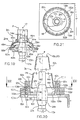
- FIG. 19 Another variant of the turning and winding device 3m is shown in Fig. 19.
- the funnel-shaped mouth 26m of the balloon limiter 14m formed by the conical flange 90m, merges into a limiting ring 28m , the boundary wall 29m, through which an orientation cavity 42m is delimited, forms an obtuse angle with the inner wall of the conical flange 90m , so that the limiting wall 29m is arranged to diverge from the axis 17 of the spindle 13m .
- the arrangement and mounting of the guide ring 94m with the guide edge 95m corresponds to the embodiment according to FIG. 12, so that the corresponding parts in FIG. 19 are identified by the same reference numbers with the index m .
- the guide edge 95m of the guide ring 94m is arranged within the limiting ring 28m in front of a plane (not shown) which is laid through the outlet end 46m - with regard to the direction of movement of the yarn P through the balloon limiter 14m - between the outlet end 46m and the spindle 13a.
- the relationship A> B, C, D applies to the turning and winding device 3 m .
- the yarn P fed over the working surface 44m expands from the circumferential contact point 47m into the rotating open loop 48 , which is formed by the inner wall of the conical flange 90m and the boundary wall 29m of the boundary ring 28m .
- the return leg of the rotating open loop 48 which is directed from the working surface 44m onto the sleeve 23m , decreases continuously as the rotating open loop 48 stretches until it touches the guide edge 95m of the guide ring 94m . This causes the backward load to brake on the leading edge 95m and a corresponding section of the yarn P to be wound onto the sleeve 23m.
- its return branch comes to a higher position, whereby the yarn winding is interrupted.
- this stretching and shortening of the rotating open loop 48 is repeated so quickly that a continuous process is created.
- the spinning device can work in different rotation ratios. It proves to be advantageous if the revolutions of the balloon limiter 14m are somewhat higher than that of the spindle 13m , but they can possibly also be the same or moderately lower. The revolutions of the rotating open loop 48 are always lower than that of the spindle 13m . This means that the rotating open loop 48 is slowed in its rotation with respect to the spindle.
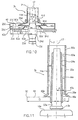
- 20 and 21 show a variant of the turning and winding device 3n with the balloon limiter 14n , which is embodied by a hollow rotating body 52n , the working surface 44n of which widens conically from the entry end 45n , which also forms the peripheral contact point 47n of the working surface 44n .
- the outlet end 26n of the working surface 44n of the balloon limiter 14n extends into the limiting ring 28n , which is formed in a body 99n fastened on a stationary ring bench 92n with a concentric opening 93n by means not shown.
- the boundary wall 29n of the boundary ring 28n merges on the one hand via the functional recess 100n into the upper radial side wall 101n of the boundary ring 28n and on the other hand via the functional gap 102n into the guide edge 95n of the guide ring 94n embodied by the lower radial side wall.
- this guide edge 94n is arranged behind a plane (not shown) through the outlet end 46n between the outlet end 46n and the boundary wall 29n .
- the guide ring 94n is axially adjustably mounted in the body 99n of the limiting ring 28n for the purpose of setting the desired height of the radial gap 43n , which ensures the guidance of the yarn P formed onto the sleeve 23n .
- the guide ring 94n is screwed with its outer, threaded shoulder 103n into the thread 104n of the inner cylindrical recess 105n in the body 99n of the limiting ring 28n .
- the cleaning openings 106n are arranged on the circumference of the upper side wall of the outer cylindrical shoulder 103n , the longitudinal axes (not shown) of which run parallel to the axis 17 of the spindle 13n .
- the orientation cavity 42n is connected by means of the functional gap 102n to the space 107n , which through the upper side wall of the outer threaded shoulder 103n of the guide ring 94n, with the wall of the inner cylindrical recess 105n of the body 99n and with the rib-shaped end 108n of the guide edge 95n of the guide ring 94n is limited.
- the direction of rotation of the spindle 13n is indicated by the arrow 41 .
- the relationship C ⁇ B, D applies to the construction of the turning and winding device 3n .
- the inner wall 109n of the guide ring 94n tapers conically from the guide edge 95n, which facilitates the piecing process of the spinning unit.
- the radial gap 43n affects the movement and guidance of the portion of the rotating open loop 48 by accurately guiding the yarn P on the sleeve 24n .
- the air flow through the radial gap 43n, caused by the movement of the yarn P is intensely dampened by its walls. This has a positive effect on the shape of the rotating open loop 48 , particularly in the area around its back bend 50 .
- the intensity of the force effect between the boundary wall 29n of the boundary ring 28n and the yarn P lying thereon is reduced.
- the resulting reduction in force results in the lowering of the friction of the yarn P and reduced wear of the boundary wall 29n .
- the spinning device can operate in different rotational ratios of the balloon limiter 14n and the spindle 13n . It proves to be very advantageous if the revolutions of the balloon limiter 14n are somewhat higher than that of the spindle 13n , they can possibly also be the same or a little lower. However, the revolutions of the rotating open loop 48 are always lower than that of the spindle 13n , which means that the rotating open loop 48 , into which the yarn P extends from the circumferential contact point 47n , is delayed in its rotation with respect to the spindle 13n .
- the cleaning openings 106n ensure the continuous removal of dust and fiber residues arising during spinning during operation.
- the impurities are removed from the radial gap 43n into the outside environment by means of the functional gap 102n, the space 107n and the cleaning openings 106n.
- these cleaning openings can be arranged obliquely with their longitudinal axes with respect to the axis 17 of the spindle 13n . As a result, a pressure drop occurs between the ends of openings, which allows the removal of a larger amount of air and thereby faster movement of the impurities out of the radial gap 43n .
- the spinning conditions for the production for example of cotton, synthetic or blended yarns, can be made of appropriate finenesses.
- the described turning and winding devices are also suitable for twisting yarn.
- the linear structure 110 from a supply spool 111 and the linear structure 112 from another supply spool 113 can here with the aid of means not shown in the direction of the arrows 114 and 115 to the outlet rollers 5 of the drafting device 4 and from there into the turning and winding device 3 for the purpose mutual connection are fed into the twine.
Landscapes
- Engineering & Computer Science (AREA)
- Mechanical Engineering (AREA)
- Textile Engineering (AREA)
- Spinning Or Twisting Of Yarns (AREA)
Claims (16)
- Un procédé de filage de broche ou de retordage, éxecuté sur la machine à filer comprenant un mécanisme d'alimentation de formation fibreux, une broche commandée pour une busette et un anneau de ballon aussi commandé et disposée coaxialment avec la broche, l' anneau de ballon, ayant sur sa face interne une surface de travail pour un contact avec un fil, characterisé en ce que le fil entraíné par la surface de travail de l'anneau de ballon est passant de la surface de travail directement sur la busette comme une boucle ouvèrte tournante, qui se détend sous l'influence d'une force centrifuge, la distance radial de la flexion reversible à l' axe de rotation de broche étant majeur que celle-ci du lieu sur la surface de travail de l'anneau de ballon d'où le fil se détend à la boucle ouvèrte tournante.
- Un procédé de filage de broche ou de retordage selon de revendication 1, characterisé en ce que la boucle ouvèrte tournante est réduite radialment au régime.
- Un procédé de filage de broche ou de retordage selon de revendication 1 ou 2, characterisé en ce qu'on produit un effet de freinage à la boucle ouvèrte tournante, formée du fil, avant d'enrouler sur la busette.
- Un dispositif à filer pour exécuter le procédé de filage de broche ou de retordage selon de quelque des revendications 1 à 3, comprenant un mécanisme d'alimentation de formation fibreux, broche commandé pour la busette et un anneau de ballon aussi commandé et disposée coaxialment avec la broche, l' anneau de ballon, ayant sur sa face interne une surface de travail pour un contact avec un fil, characterisé en ce que le lieu de montée periphérique (47 à 47n) est disposé sur la surface de travail (44 à 44n) pour la transition du fil (P) de cette surface de travail (44 à 44n) directement sur la busette (23 à 23n), le fil (P) se constituant à la forme de la boucle ouvèrte tournante (48) sous l'influence de la force centrifuge, et chaque lieu de surface de travail (44 à 44n) dont la distance d'extrémité d'entre (45 à 45n) de l'anneau de ballon (14 à 14n) est majeur que celle-ci du lieu de montée periphérique (47 à 47n) est disposé de façon que sa distance de l' axe de rotation (17) de broche (13 à 13n) étant majeur que celle-ci du lieu de montée periphérique (47 à 47n).
- Un dispositif à filer selon de revendication 4, characterisé en ce que de l'anneau de ballon (14à 14f, 14h à 14n) est muni d'un orifice d'entonnoir (26 à 26f, 26h à 26n).
- Un dispositif à filer selon de revendication 4, characterisé en ce que de l'anneau de ballon (14 à 14d, 14i à 14n) est enchainé, dans le sense de mouvement de fil (P) à travers de l'anneau de ballon (14 à 14d, 14i à 14n), sur un anneau coaxial de limitation (28 à 28d, 28i à 28n) comprenant une paroi de limitation (29 à 29d, 29g, 29i à 29n) pour une limitation radial de la boucle ouvèrte tournante (48), la distance radial (B) de la paroi de limitation (29 à 29d, 29g; 29i à 29n) de l' axe (17) de broche (13 à 13d; 13g; 13i à 13n) étant majeur que celle-ci (A) du lieu de montée periphérique (47 à 47d, 47g; 47i à 47n) de l' axe (17) de broche (13 à 13d; 13g; 13i à 13n)
- Un dispositif à filer selon de revendication 6, characterisé en ce que de l'anneau coaxial de limitation (28b, 28d, 28g, 28i, 28k, 281, 28n) est non rotatif.
- Un dispositif à filer selon de revendication 6, characterisé en ce que l'anneau de limitation (28, 28c), soit passe en d'orifice d'entonnoir (26 26c) de l'anneau de ballon (14, 14c) soit en de paroi latéral (30, 30c) opposée à l'orifice d'entonnoir (26 26c) et munie d'un trou axial pour passage de la busette (23 à 23c) avec la broche (13, 13c), l'anneau coaxial de limitation (28, 28c), d'orifice d'entonnoir (26 26c) et paroi latéral (30, 30c) définissant un creux de redressement (42;42c) pour bobinage de fil (P) de la boucle ouvèrte tournante (48) sur la busette (23 à 23n) de la broche (13, 13c).
- Un dispositif à filer selon de revendication 4, characterisé en ce que l'anneau de ballon coaxial non rotatif (66a, 66e) est incorporé avant l'anneau de ballon (14a, 14c).
- Un dispositif à filer selon de revendication 6, characterisé en ce que la paroi de limitation (29) d'anneau coaxial de limitation (28) est munie de trous d'air (49).
- Un dispositif à filer selon de revendication 4, characterisé en ce que l'anneau de guidage (94d, 94f, 941 à 94n) stationaire et coaxial avec la broche (13d, 13f, 131 à 13n) est incorporé à l'anneau de ballon (14d, 14f, 141 à 14n), l'anneau de guidage (94d, 94f, 941 à 94n) étant muni d'une arête de guidage (95d, 95f, 951 à 95n) produissant un effet de freinage au fil avant son enroulement sur la busette (23d, 23f, 231 à 23n).
- Un dispositif à filer selon de revendication 11, characterisé en ce que l'arête de guidage (95d, 95f, 951 à 95n) de l'anneau de guidage (94d, 94f, 941 à 94n) est disposée entre l'extrémité de sortie (46d, 46f, 46m) de la surface de travail (44d, 44f, 44) et la broche (13d, 13f, 13m).
- Un dispositif à filer selon de revendication 11, characterisé en ce que l'arête de guidage (951, 95n) de l'anneau de guidage (941, 94n) est disposée entre l'extrémité de sortie (461, 46n) de la surface de travail (441, 44n) et la paroi de limitation (291, 29n) de l'anneau coaxial de limitation (281, 28n)
- Un dispositif à filer selon de revendication 11, characterisé en ce que l'arête de guidage (95d, 951, 95m) de l'anneau de guidage (94d, 941, 94m) atteint dans l'anneau coaxial de limitation (28d, 281, 28m).
- Un dispositif à filer selon de revendication 11, characterisé en ce que l'arête de guidage (95n) de l'anneau de guidage (94n) est formé par la paroi inférieur latéral radial, ce paroi en commun avec la paroi supérieur latéral radial (101n) et la paroi de limitation (29n) définissant un creux de redressement (42n) pour la boucle ouvèrte tournante (48) et en ce que l'anneau de guidage (94n) est posé réglablement axialment dans la corps (99n) de l'anneau coaxial de limitation (28n).
- Un dispositif à filer selon de revendication 15, characterisé en ce que des trous de nettoyage (106n) sont fait sur la périphérie de l'anneau de guidage (94n), ces trous joignant pneumatique un creux de redressement (42n) à travers un jeu de fonction (102n) entre le corps (99n) de l'anneau coaxial de limitation (28n) et de l'anneau de guidage (94n) avec l'espace environnant.
Applications Claiming Priority (3)
| Application Number | Priority Date | Filing Date | Title |
|---|---|---|---|
| CZ596 | 1996-02-28 | ||
| CZ59696 | 1996-02-28 | ||
| PCT/CZ1997/000009 WO1997032065A1 (fr) | 1996-02-28 | 1997-02-24 | Procede de filage ou de retordage sur broche et unite de travail pour la mise en oeuvre du procede |
Publications (2)
| Publication Number | Publication Date |
|---|---|
| EP0883703A1 EP0883703A1 (fr) | 1998-12-16 |
| EP0883703B1 true EP0883703B1 (fr) | 2001-11-28 |
Family
ID=5461956
Family Applications (1)
| Application Number | Title | Priority Date | Filing Date |
|---|---|---|---|
| EP97904336A Expired - Lifetime EP0883703B1 (fr) | 1996-02-28 | 1997-02-24 | Procede de filage ou de retordage sur broche et unite de travail pour la mise en oeuvre du procede |
Country Status (4)
| Country | Link |
|---|---|
| US (1) | US6182434B1 (fr) |
| EP (1) | EP0883703B1 (fr) |
| DE (1) | DE59705546D1 (fr) |
| WO (1) | WO1997032065A1 (fr) |
Families Citing this family (10)
| Publication number | Priority date | Publication date | Assignee | Title |
|---|---|---|---|---|
| CZ286823B6 (cs) * | 1998-01-28 | 2000-07-12 | Výzkumný Ústav Bavlnářský A. S. | Vřetenové spřádací nebo skací zařízení |
| CZ286824B6 (cs) * | 1998-05-20 | 2000-07-12 | Výzkumný Ústav Bavlnářský A. S. | Zařízení pro vřetenové předení nebo skaní |
| CZ199198A3 (cs) * | 1998-06-24 | 2000-04-12 | Výzkumný Ústav Bavlnářský A. S. | Spřádací stroj |
| CZ2003588A3 (en) * | 2003-02-28 | 2004-10-13 | Výzkumnýáústavábavlnářskýááa@Ás | Device for spinning or twisting loops |
| CZ20041160A3 (cs) * | 2004-12-01 | 2006-07-12 | VÚB a. s. | Zarízení pro smyckové predení nebo skaní |
| ES2616332T3 (es) * | 2007-04-17 | 2017-06-12 | International Textile Group, Inc. | Tejido de mezclilla |
| US8079206B2 (en) * | 2009-10-02 | 2011-12-20 | Abdul Latif Abbasi | Ring spinning mechanism with fixed ring location |
| TR201606346A2 (tr) * | 2016-05-13 | 2017-01-23 | Sanko Tekstil Isletmeleri Sanayi Ve Ticaret Anonim Sirketi | Balon çapının kontrol edilmesini sağlayan aparat |
| US11598027B2 (en) | 2019-12-18 | 2023-03-07 | Patrick Yarn Mills, Inc. | Methods and systems for forming a composite yarn |
| DE102021101435A1 (de) * | 2021-01-22 | 2022-07-28 | Saurer Spinning Solutions Gmbh & Co. Kg | Spinneinrichtung mit schwebendem Spinnring und Ballonbegrenzerhülse |
Family Cites Families (13)
| Publication number | Priority date | Publication date | Assignee | Title |
|---|---|---|---|---|
| US2833111A (en) | 1955-10-20 | 1958-05-06 | Spinnerei Karl Marx Veb | Cap spinning frames and cap twisting frames |
| CH644639A5 (fr) | 1980-12-08 | 1984-08-15 | Heberlein Hispano Sa | Dispositif pour le filage continu de fils textiles. |
| DE3140422A1 (de) | 1981-10-12 | 1983-04-21 | Zinser Textilmaschinen Gmbh, 7333 Ebersbach | Textilmaschine, insbesondere ringspinn- oder zwirnmaschine |
| DE3400327A1 (de) * | 1984-01-07 | 1985-07-18 | Zinser Textilmaschinen Gmbh, 7333 Ebersbach | Glockenspinnvorrichtung |
| IT1218462B (it) * | 1985-12-10 | 1990-04-19 | Cerimates Spa | Procedimento e sistema di filatura a limitatore di balloon rotante |
| IT1214219B (it) * | 1987-09-08 | 1990-01-10 | Cerit Spa | Dispositivo di controllo del riattacco del filato su filato. |
| US4862287A (en) | 1987-09-30 | 1989-08-29 | Mendon Electronics Corporation | Power line monitor and printer system |
| DE3741432A1 (de) * | 1987-12-08 | 1989-06-22 | Zinser Textilmaschinen Gmbh | Spinnvorrichtung |
| DE4103369A1 (de) | 1990-03-03 | 1991-09-05 | Stahlecker Fritz | Magnetlagerung |
| US5109659A (en) | 1990-06-01 | 1992-05-05 | Tns Mills, Inc. | Magnetic ring for the spinning of textile yarn and method |
| CH682405A5 (de) * | 1990-11-16 | 1993-09-15 | Rieter Ag Maschf | Einrichtung zur Ummantelung einer Spinnvorrichtung. |
| CZ278771B6 (en) | 1991-01-24 | 1994-06-15 | Vyzk Ustav Bavlnarsky A S | Apparatus for continuous spinning of textile yarns |
| JP3515574B2 (ja) * | 1993-06-30 | 2004-04-05 | フォルシュングスツェントルム・ユーリッヒ・ゲゼルシャフト・ミト・ベシュレンクテル・ハフツング | 精紡機並びにその制御および調整装置 |
-
1997
- 1997-02-24 US US09/125,554 patent/US6182434B1/en not_active Expired - Fee Related
- 1997-02-24 EP EP97904336A patent/EP0883703B1/fr not_active Expired - Lifetime
- 1997-02-24 DE DE59705546T patent/DE59705546D1/de not_active Expired - Fee Related
- 1997-02-24 WO PCT/CZ1997/000009 patent/WO1997032065A1/fr not_active Ceased
Also Published As
| Publication number | Publication date |
|---|---|
| WO1997032065A1 (fr) | 1997-09-04 |
| US6182434B1 (en) | 2001-02-06 |
| EP0883703A1 (fr) | 1998-12-16 |
| DE59705546D1 (de) | 2002-01-10 |
Similar Documents
| Publication | Publication Date | Title |
|---|---|---|
| DE19815054C1 (de) | Verfahren und Spinnmaschine zum Herstellen von Coregarn | |
| DE19815050B4 (de) | Verdichtungsstreckwerk für eine Spinnmaschine | |
| WO2008068294A1 (fr) | Dispositif et procédé d'amenée de flammes sur des métiers à filer à anneaux | |
| DE1760568A1 (de) | Verfahren und Vorrichtung zum Spinnen von Fasermaterial unter Verwendung einer Rotationsspinnkammer | |
| CH682826A5 (de) | Spinnmaschine. | |
| DE10236450A1 (de) | Spinnmaschine mit einem Mehrstufen-Verdichtungs-Streckwerk | |
| WO2004042126A1 (fr) | Procede et dispositif pour produire une meche | |
| CH645417A5 (de) | Kerngarn, verfahren zu dessen herstellung und anordnung zum ausfuehren dieses verfahrens. | |
| EP0883703A1 (fr) | Procede de filage ou de retordage sur broche et unite de travail pour la mise en oeuvre du procede | |
| EP0947618B1 (fr) | Procédé et machine à filer d'un fil | |
| EP3842578B1 (fr) | Métier à filer à anneaux et procédé de fabrication d'un fil à âme | |
| DE19815052B4 (de) | Verfahren zum Herstellen eines Garnes und Spinnmaschine hierfür | |
| DE2831506C2 (fr) | ||
| DE2645119C3 (de) | Verfahren zur Herstellung eines Coregaras | |
| DE19927838A1 (de) | Vorrichtung zur Herstellung gesponnener Fäden | |
| WO2023217322A1 (fr) | Banc d'étirage, machine de traitement de fibres à banc d'étirage et procédé pour faire fonctionner un banc d'étirage | |
| DE102020118327A1 (de) | Verfahren und Vorrichtung zur Falschdrahteinleitung sowie Spinnmaschine | |
| DE3135363A1 (de) | Verfahren und vorrichtung zum offenend-spinnen | |
| DE19609515A1 (de) | Verfahren und Vorrichtung zum Umwinden von aus einer Spinnkanne einer Spinnmaschine ablaufendem Faserband mit endlosem Filamentgarn | |
| DE3206431A1 (de) | Verfahren und anlage bzw. ringspinnmaschine zur herstellung von effektgarn | |
| WO2004076727A1 (fr) | Dispositif de filage ou de retordage avec bouclage | |
| DE3920813A1 (de) | Verfahren zum verspinnen von aufgeloesten fasern von linearer textiler struktur auf der grundlage von diskontinuierlichen fasern, und vorrichtung zur durchfuehrung des verfahrens | |
| DE3023074A1 (de) | Vorrichtung zur herstellung von umwindegarnen | |
| DE19545066A1 (de) | Korbverseilmaschine | |
| DE3535647A1 (de) | Faserstrang aus hanf, flachs oder dgl. |
Legal Events
| Date | Code | Title | Description |
|---|---|---|---|
| PUAI | Public reference made under article 153(3) epc to a published international application that has entered the european phase |
Free format text: ORIGINAL CODE: 0009012 |
|
| 17P | Request for examination filed |
Effective date: 19980622 |
|
| AK | Designated contracting states |
Kind code of ref document: A1 Designated state(s): CH DE IT LI |
|
| 17Q | First examination report despatched |
Effective date: 19990917 |
|
| GRAG | Despatch of communication of intention to grant |
Free format text: ORIGINAL CODE: EPIDOS AGRA |
|
| GRAG | Despatch of communication of intention to grant |
Free format text: ORIGINAL CODE: EPIDOS AGRA |
|
| GRAH | Despatch of communication of intention to grant a patent |
Free format text: ORIGINAL CODE: EPIDOS IGRA |
|
| GRAH | Despatch of communication of intention to grant a patent |
Free format text: ORIGINAL CODE: EPIDOS IGRA |
|
| GRAA | (expected) grant |
Free format text: ORIGINAL CODE: 0009210 |
|
| AK | Designated contracting states |
Kind code of ref document: B1 Designated state(s): CH DE IT LI |
|
| RIN1 | Information on inventor provided before grant (corrected) |
Inventor name: DIDEK, STANISLAV Inventor name: BLAZEK, PETR Inventor name: KUBOVY, VACLAV |
|
| REG | Reference to a national code |
Ref country code: CH Ref legal event code: EP |
|
| REF | Corresponds to: |
Ref document number: 59705546 Country of ref document: DE Date of ref document: 20020110 |
|
| REG | Reference to a national code |
Ref country code: CH Ref legal event code: NV Representative=s name: R. A. EGLI & CO. PATENTANWAELTE |
|
| PLBE | No opposition filed within time limit |
Free format text: ORIGINAL CODE: 0009261 |
|
| STAA | Information on the status of an ep patent application or granted ep patent |
Free format text: STATUS: NO OPPOSITION FILED WITHIN TIME LIMIT |
|
| 26N | No opposition filed | ||
| REG | Reference to a national code |
Ref country code: CH Ref legal event code: PFA Owner name: VUB A.S. Free format text: VYZKUMNY USTAV BAVLN?RSKY#NA OSTROVE 1165#562 23 UST? NAD ORLIC? (CZ) -TRANSFER TO- VUB A.S.#NA OSTROVE 1165#562 23 UST? NAD ORLIC? (CZ) |
|
| REG | Reference to a national code |
Ref country code: CH Ref legal event code: PUE Owner name: MASCHINENFABRIK RIETER AG Free format text: VUB A.S.#NA OSTROVE 1165#562 23 USTI NAD ORLICI (CZ) -TRANSFER TO- MASCHINENFABRIK RIETER AG#KLOSTERSTRASSE 20#8406 WINTERTHUR (CH) |
|
| PGFP | Annual fee paid to national office [announced via postgrant information from national office to epo] |
Ref country code: CH Payment date: 20080215 Year of fee payment: 12 |
|
| PGFP | Annual fee paid to national office [announced via postgrant information from national office to epo] |
Ref country code: IT Payment date: 20080223 Year of fee payment: 12 Ref country code: DE Payment date: 20080219 Year of fee payment: 12 |
|
| REG | Reference to a national code |
Ref country code: CH Ref legal event code: PL |
|
| PG25 | Lapsed in a contracting state [announced via postgrant information from national office to epo] |
Ref country code: LI Free format text: LAPSE BECAUSE OF NON-PAYMENT OF DUE FEES Effective date: 20090228 Ref country code: CH Free format text: LAPSE BECAUSE OF NON-PAYMENT OF DUE FEES Effective date: 20090228 |
|
| PG25 | Lapsed in a contracting state [announced via postgrant information from national office to epo] |
Ref country code: DE Free format text: LAPSE BECAUSE OF NON-PAYMENT OF DUE FEES Effective date: 20090901 |
|
| PG25 | Lapsed in a contracting state [announced via postgrant information from national office to epo] |
Ref country code: IT Free format text: LAPSE BECAUSE OF NON-PAYMENT OF DUE FEES Effective date: 20090224 |