EP0883708B1 - Haarstechmaschine - Google Patents
Haarstechmaschine Download PDFInfo
- Publication number
- EP0883708B1 EP0883708B1 EP96946325A EP96946325A EP0883708B1 EP 0883708 B1 EP0883708 B1 EP 0883708B1 EP 96946325 A EP96946325 A EP 96946325A EP 96946325 A EP96946325 A EP 96946325A EP 0883708 B1 EP0883708 B1 EP 0883708B1
- Authority
- EP
- European Patent Office
- Prior art keywords
- positive
- stitching
- hair
- positive mould
- needle
- Prior art date
- Legal status (The legal status is an assumption and is not a legal conclusion. Google has not performed a legal analysis and makes no representation as to the accuracy of the status listed.)
- Expired - Lifetime
Links
- 210000004209 hair Anatomy 0.000 claims abstract description 64
- 239000000463 material Substances 0.000 claims abstract description 7
- 238000003780 insertion Methods 0.000 claims abstract description 5
- 230000037431 insertion Effects 0.000 claims abstract description 5
- 102100022615 Cotranscriptional regulator FAM172A Human genes 0.000 claims abstract description 3
- 101000823488 Homo sapiens Cotranscriptional regulator FAM172A Proteins 0.000 claims abstract description 3
- 238000000034 method Methods 0.000 claims description 14
- 230000008569 process Effects 0.000 claims description 11
- 230000005540 biological transmission Effects 0.000 claims description 5
- 229920003023 plastic Polymers 0.000 claims description 3
- 239000004033 plastic Substances 0.000 claims description 2
- 239000000725 suspension Substances 0.000 claims 3
- 229910052602 gypsum Inorganic materials 0.000 claims 1
- 239000010440 gypsum Substances 0.000 claims 1
- 229920003002 synthetic resin Polymers 0.000 claims 1
- 239000000057 synthetic resin Substances 0.000 claims 1
- 239000000853 adhesive Substances 0.000 abstract description 3
- 230000001070 adhesive effect Effects 0.000 abstract description 3
- 239000002985 plastic film Substances 0.000 abstract 1
- 239000011347 resin Substances 0.000 abstract 1
- 229920005989 resin Polymers 0.000 abstract 1
- 210000003128 head Anatomy 0.000 description 12
- 239000010410 layer Substances 0.000 description 8
- 238000011161 development Methods 0.000 description 6
- 230000018109 developmental process Effects 0.000 description 6
- 230000007246 mechanism Effects 0.000 description 4
- 230000008901 benefit Effects 0.000 description 3
- 230000008859 change Effects 0.000 description 3
- 238000012549 training Methods 0.000 description 3
- 239000011324 bead Substances 0.000 description 2
- 238000012937 correction Methods 0.000 description 2
- 239000004744 fabric Substances 0.000 description 2
- 239000011888 foil Substances 0.000 description 2
- 238000002347 injection Methods 0.000 description 2
- 239000007924 injection Substances 0.000 description 2
- 229920002160 Celluloid Polymers 0.000 description 1
- -1 Gauze Substances 0.000 description 1
- 239000012790 adhesive layer Substances 0.000 description 1
- 150000001875 compounds Chemical class 0.000 description 1
- 238000013461 design Methods 0.000 description 1
- 238000010586 diagram Methods 0.000 description 1
- 238000006073 displacement reaction Methods 0.000 description 1
- 238000011156 evaluation Methods 0.000 description 1
- 239000011152 fibreglass Substances 0.000 description 1
- 230000003803 hair density Effects 0.000 description 1
- 238000007373 indentation Methods 0.000 description 1
- 238000004091 panning Methods 0.000 description 1
- 230000035515 penetration Effects 0.000 description 1
- 239000011505 plaster Substances 0.000 description 1
- 210000004761 scalp Anatomy 0.000 description 1
- 238000000926 separation method Methods 0.000 description 1
- 239000000243 solution Substances 0.000 description 1
- 239000000126 substance Substances 0.000 description 1
- 230000001960 triggered effect Effects 0.000 description 1
- XLYOFNOQVPJJNP-UHFFFAOYSA-N water Substances O XLYOFNOQVPJJNP-UHFFFAOYSA-N 0.000 description 1
- 239000013585 weight reducing agent Substances 0.000 description 1
Images



Classifications
-
- D—TEXTILES; PAPER
- D05—SEWING; EMBROIDERING; TUFTING
- D05C—EMBROIDERING; TUFTING
- D05C15/00—Making pile fabrics or articles having similar surface features by inserting loops into a base material
- D05C15/02—Rooting of hair in doll heads or wigs
Definitions
- the invention relates to a hair piercing machine Bribing an artificial hair piece (toupee) after the Preamble of claim 1.
- the state of the art include program-controlled placement machines such.
- the assembly of the boards is done in such a way that the board is firmly arranged and the insertion arm holding the element to be inserted is program-controlled visits the assembly location and uses the element. Then moved the loading arm towards the element storage to pick up the next element.
- the disadvantage here is the complex and extensive mechanics for moving the Needle head.
- the needle head must also have all the elements, such as stepper motors, Gearboxes etc. included, so that great weight reduction requirements of the individual parts must be put.
- Another problem with bribing a hair piece is that the individual Puncture points are not calculated, e.g. B. on a circuit board based on the circuit diagram, but must be determined depending on the person. This should be done in one special scanning device. The evaluation of the data could be used for control the piercing needle can be used.
- the device for producing wigs etc. known from JP-A-63 219 663 has two needles, only one of which is perpendicular to the tangent, and one perpendicular rotating table that swivels on one arm, with the arm horizontal on one rotating part is attached.
- the object of the invention specified in claim 1 is a hair piercing machine specify according to the preamble of claim 1, in which the cost of materials and the moving mass is as small as possible.
- the hair piercing machine according to claim 1 is disregarded of the advantages resulting from the solution of the task, achieved that the drive and actuating elements for Establishing the puncture position housed in the housing and the control commands for the stepper motors and all other very important for hair of the artificial hair part Data such as hair distance, hair density and deviations of the Head surface from the average head shape without previous Change of position of the with the placed hair piece foil provided positive form immediately before the lancing process Change in the position of the positive form can be determined can.
- the machine can be operated in a few simple steps possible.
- the T-shaped holding device only needs to be turned, to either the scanner or the piercing needle Bring work position over the positive form.
- the development according to claim 3 allows, optionally different independent positions of the holding arms without adjustment, and prevents the holding arms moved unintentionally from the working position become.
- the holding arms can be swung away that the positive form is completely freely accessible.
- the development according to claim 4 facilitates filling of the hair and prevents damage when swinging away the Hair feeding by bumping against the back wall of the room.
- the development according to claim 5 enables adjustment the positive shape in the desired puncture position.
- the training according to claim 6 extends the adjustment the positive form in case the head form has larger flat surfaces.
- the development according to claim 7 facilitates assembly of the hair piece and reduces the material expenditure.
- the development according to claim 9 reduces the in the housing the machine housed effort for swiveling and enables the coordinated tilting of positive form and Needle holder.
- Fig. 1 the (partly only indicated) housing 2 is on the top completed with the mounting plate 11.
- the positive form 12a On the mounting plate 11 is the positive form 12a, optionally divided in a positive stump and a positive shell, movable arranged.
- the cuff 46 covers the recess in the Mounting plate 11.
- the cuff 46 covers the opening in the mounting plate 11.
- Close to the The rear wall of the housing 2 is the support column 49 for the holding arms 37a and 37b.
- One arm 37b carries the Scanning device 50, which is currently in its working position, and exactly above the geometric center the positive form 12a. If necessary, the column can be twist so that the short holding arms of the positive form can be pivoted away.
- the holding arms 37a and 37b (Figs. 1 and 2) preferably close an angle of 90 degrees.
- the holding arm 37a with the encapsulated piercing needle head 15 is therefore in the rest position swung away to the side.
- a swivel 51 which the Connection of the holding arms 37a and 37b to the support column 49 manufactures.
- the holding arms 37a and 37b rigid with the support column extending into the housing 2 49 connected and the swivel 51 can be arranged there.
- Fig. 2 are the positions of the two holding arms 37a and 37b rotated 90 degrees clockwise, so that now the piercing needle head 15 in the working position above the Positive form 12a and the scanning device 50 in the rest position located.
- the holding arm 37b in Fig. 1 as a longitudinal part of a lying T's be formed (not shown) on the two free (short) ends of the scanner 50 (at one End) and the needle head 15 (at the other end) are mounted.
- the T-shaped holding device is on the Column 49 - rigid in the horizontal direction - via a swivel joint rotatable and enables by turning 180 degrees that either the scanning device or the needle head in Working position is brought.
- the holding arms 37a and 37b as shown in Fig. 1 and 2 are independent are to be moved from one another, then the a joint 51 two joints one above the other (not shown), each provided with individual rest positions, provided that allow that both holding arms 37a and 37b also pivoted into the rear rest position at the same time can be, e.g. B. in the event that the hairpiece examined in detail or individual hairs manually retouched Need to become.
- the distributor shaft can either be folded up and / or removed, to make filling the hair easier and to avoid that when the machine 1 is close to the wall Swiveling his holding arm 37a hits the wall and is damaged.
- the - The holding arm 37b with the scanning device 50 is located in FIG the working position according to Fig.1 - the hair piece on the surface the positive form 12a optically scanned and the data including those about the size and location of the hair piece as well Density of the intended hair in a computer system saved.
- the stepper motor runs a standard program for moving the positive mold 12a with all future puncture points in the hairpiece located and their respective surface after deviation from normal rounding (dents and bumps in the head shape) be determined and evaluated.
- the surface data deliver in combination with a special program three-dimensional image of the hair piece on the head.
- the surface is first the positive form 12a optically scanned and the data including those about the size and location of the hair piece as well Density of hair is stored in a computer system.
- the stepper motors for moving the positive form 12a from a standard program with which all future puncture points in the hairpiece and their respective surface after deviation from normal rounding (Dents and bumps in the head shape) and be rated.
- the surface data deliver in combination with a special program a three-dimensional image of the hair piece on the head.
- the data is the computer supplied, which determines the control data for all drives.
- the computing device can be separately or in the housing 2 Hair piercing machine 1 may be arranged.
- the hair feeder 31 consists of a distributor shaft 32, into which the hair is inserted in bundles and in which the hair by a distribution arrangement, not shown, for. B. by counter-rotating rubber rollers, individually the Endless belt device 33 are supplied.
- the endless belt device 33 consists of at least two endless belts, each provided with grooves 34 for one hair each. Two endless belts are arranged directly next to each other in such a way that the piercing needle 29 fits between them during the piercing process. The hair lies on the endless belt device 33 that the end of the hair facing the piercing needle 29 each extends beyond the endless belt device 33 by approximately 2 cm.
- the holding arms 37a and 37b are used for piercing the hair pivoted, d. H. the scanning device 51 in the rest position and the piercing needle head 15 in the working position above the positive form 12a (Fig. 2). With the triggering of the The stepper motors in the bribery program Inside the housing 2, the step commands from the Computing device.
- the lancing process can be triggered by hand become.
- Fixed, adjustable limits for the end positions ensure that the needle penetration depth and stroke remain unchanged while working on the hairpiece. With the piercing, a spring is tensioned, its tension is selectable. So the needle goes automatically after everyone Puncture back to the rest position.
- the positive form 12a is below the sleeve 46 by means of a quick release, not shown, with the tilt drives 44 and 45 (Fig. 3) detachable or as a positive shell 12b, c firmly connected.
- the following is always when it is are short axes of rotation, the term “tilting” used, otherwise, i.e. with relatively long axes of rotation the term “panning".
- the positive form 12a although it specially made for each hair piece and therefore only once can be used from hard but light (and therefore consist of expensive) material.
- the positive form 12a as fixed with the tilt drive 44 stump connected via the fastening plate 48 12c, on the form-fitting a positive shell 12b, on which the hair piece to be bribed is pulled with known closure means immovable, but removable can be held, as detailed in the Fig. 4 and 5 is shown.
- the positive shell 12b made of cheap material (e.g. plaster) may exist while for the positive stump 12c, which is a permanent part of the adjustment device forms, the most suitable material without equity considerations can be chosen. So that the positive shell 12b always in the same position on the positive stump 12c are on the contact surfaces of the positive shell 12b and positive stump 12c interlocking profiles 59, e.g. B. beads and notches with corresponding recesses, intended.
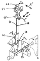
- Fig. 3 are the adjustment means shown for the positive form 12a.
- the tilt drives 44 and 45 each consisting of stepper motor and gearbox, the positive form 12a about the X axis and the Y axis can be tilted. Then these movements are required if the puncture level at the puncture point, e.g. B. not for bumps in the head shape of the hairpiece wearer is perpendicular to the piercing needle and should therefore be corrected got to.
- the support arm 39 therefore connects the tilt drives 44 and 45 at the required distance with the high-low drive 41, also consisting of engine and transmission, which first of all the superscript and subscript of the positive form 12a guaranteed.
- the support arm 39 has a ring gear and is guided in the housing for the high-low drive 41. With the high-low drive 41 including the distance change between the positive form 12a and the piercing needle, by the support arm 39 in the Z axis, corresponding to the respective direction to the injection site.
- the housing for the high-low drive 41 is fixed to the first Swivel drive 42 (stepper motor and gearbox) connected, whereby the arm 39 with the others with it connected elements (positive form 12a, tilt drives 44 and 45) about the X axis, ie in the direction of rotation "D" can.
- the second swivel drive 42 acts on the second Swivel drive 43 (stepper motor and gearbox) to the entire arrangement (1st swivel drive 42, high-low drive 41, support arm 39, tilt drives 44 and 45 and positive shape 12a) to tilt about the Y axis, ie in the direction of rotation "E".
- the adjustment axis of the 2nd swivel drive 43 is at the Side walls of the housing 2 attached so that the motor of the 2. Swivel drive 43 is also tilted.
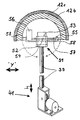
- the positive mold (12a in Fig. 1) into a positive shell 12b, who wears or is supposed to wear the hair piece, and one the positive stump corresponding further inner positive shell 12c divided.
- guide beads 59 which are preferably one have a triangular cross section.
- the (outer) positive shell 12b projects from the two shells Ends slightly beyond the inner positive shell 12c.
- the tilt drives 44 and 45 is in the second embodiment the inner positive shell 12c via an inside the gimbal 51 mounted on the positive shell 12c connected to the support arm 39.
- the gimbal 51 consists of the 1st gimbal mount 52, with attached 1.
- Cardan drive (engine and transmission) 53 on the one hand directly with the support arm 39 and on the other hand via the axes of rotation 54 with the second gimbal attachment (engine and gearbox) 55 is connected.
- 1st cardan drive 53 inner positive shell 12c can be rotated about the "X" axis.
- the 2nd gimbal drive (Motor and transmission) 56 On the 2nd gimbal mount 55 is the 2nd gimbal drive (Motor and transmission) 56 arranged, the axis of rotation 57 outside the 2nd gimbal 55 each in firm connections 58 to the inner positive shell 12c passes (Fig. 4).
- the second cardan drive 56 does this Rotate the positive shell 12c around the "Y" axis.
- the inner positive shell 12c can about 90 degrees be twisted on all sides. Because the intersection of the Axes of rotation 54 and 57 lies in the center of a circle that is averaged from a variety of head shapes the corrections for the steepness of the piercing needle on the ground minimize deviations from the normal head shape.
- Step switching means e.g. B. stepping solenoids used especially when only a few switching steps are carried out Need to become.
- the support arm 39 can if necessary also be moved so far down that the positive form 12a or the inner positive shell 12c with or without (outer) Positive shell 12b completely below the mounting plate 11 disappears.
- the recess in the mounting plate 11 can then be closed with a cover.
- Rotary actuators 42 and 43 can be easily displacement drives (not shown) are replaced, such that the high-low drive 41 for height adjustment the positive form 12a and those above the high-low drive 41 arranged elements not pivoted, but just to be moved along the "X" and "Y" axes need.
- swivel drives also in the piercing needle head 15 be relocated.
- the details is not shown separately, the high-low drive 41 firmly connected to the housing 2. Its previous function takes over a second drive set (part-turn drives 42 and 43) corresponding drive set, that in the needle holder is housed and the piercing needle head 15th tilts.
- the head shape and the direction of the puncture Correct the piercing needle so that it can also be attached to it If the spots penetrate vertically into the hairpiece, the tipping means grip for the piercing needle in its holder at one (turning) point from the injection point in the hairpiece is as far away as the puncture point from the center of rotation the gimbal 51. Compliance with this condition can be facilitated by the fact that in addition to the support arm 39 for the positive form 12a also the support column 49 for the Holding arms 37a and 37b is height adjustable.
- the Provided in the needle head 15 sensors for measuring the Distance to the puncture point offer the possibility of ideal distance automatically or after display by hand adjust.
Landscapes
- Engineering & Computer Science (AREA)
- Chemical & Material Sciences (AREA)
- Materials Engineering (AREA)
- Textile Engineering (AREA)
- Surgical Instruments (AREA)
- Sewing Machines And Sewing (AREA)
Description
- Abb. 1
- die Haarstechmaschine in der Gesamtansicht, mit der Abtastvorrichtung in Arbeitsstellung,
- Abb. 2
- die Haarstechmaschine in der Gesamtansicht, mit der Stechvorrichtung in Arbeitsstellung,
- Abb. 3
- eine erste Ausführungsform für den Verstellmechanismus für die Positivform,
- Abb. 4
- eine zweite Ausführungsform für den Verstellmechanismus für die Positivform in Frontansicht und
- Abb. 5
- die zweite Ausführungsform für den Verstellmechanismus für die Positivform um 90 Grad gedreht.
Claims (9)
- Haarstechmaschine zum Bestechen eines künstlichen Haarteils (Toupets), mit Haaren unter Verwendung von dünnen auf einer harten Positivform übereinander angeordneten transparenten Kunststoffolien aus PVC, in die die einzelnen Haare von oben eingestochen und nach dem Einstechen aller Haare in weiteren Verfahrensschritten, insb. unter Verwendung von Kunstharz mit der Träger-Folie verklebt und verpreßt werden, bestehend aus einem die Steuerelemente für die Schrittschaltmotore zum Verstellen des bewegliche Elemente enthaltenden, schrankartigen Gehäuses, oberhalb dessen als Montageplatte ausgebildeten Oberseite die Stechnadel mit einer Haarzuführung angeordnet ist,
gekennzeichnet durch eine hoch-tief- und kippbewegliche Positivform (12a), die auch schrittweise und derart dreidimensional zur Stechnadel verstellbar ist, daß die oberhalb der Positivform (12a) angeordnete Stechnadel beim Stechakt jeweils senkrecht zur Tangente der Oberfläche der Positivform (12a) im Einstichpunkt einsticht, und durch eine Haltevorrichtung (37a, 37b, 49) mit zwei oberhalb der Positivform (12a) verschwenkbaren Haltearmen (37a,37b), an deren einem Haltearm (37a) der Stechnadelkopf (15) mit Haarzuführung (32, 33) und an dessen anderem Haltearm (37b) eine Abtastvorrichtung (50) für das auf der Positivform (12a) liegende unbestochene Haarteil angeordnet sind. - Maschine nach Anspruch 1, dadurch gekennzeichnet, daß die Haltearme (37a, 37b) der Haltevorrichtung (37a, 37b, 49) die kurzen Enden eines T-Stückes bilden, dessen langes Ende waagerecht und drehbar angeordnet ist, derart, daß sich mindestens entweder die Abtastvorrichtung (50) oder der Stechnadelkopf (15) in der Arbeitsstellung für den Abtastvorgang bzw. für den Stechvorgang befindet.
- Maschine nach Anspruch 1, dadurch gekennzeichnet, daß die Haltearme (37a, 37b) der Haltevorrichtung (37a, 37b, 49) abhängig oder unabhängig voneinander waagerecht verschwenkbar sind und jeweils in mehreren Raststellungen mechanisch oder elektronisch gesichert einrastbar sind, in denen sich mindestens entweder die Abtastvorrichtung (50) oder der Stechnadelkopf (15) in der Arbeitsstellung für den Abtastvorgang bzw. für den Stechvorgang befindet (Abb. 1, 2).
- Maschine nach einem der Ansprüche 1 bis 3, dadurch gekennzeichnet, daß die der Verteilerschacht (32) für die Haarzuführung hochklapbar und/oder abnehmbar ist.
- Maschine nach einem der Ansprüche 1 bis 4, dadurch gekennzeichnet, daß die Positivform (12a) über Getriebeanordnung (44,45), bestehend aus zwei mit einander fest verbundenen Antrieben (44,45), die ein Kippen der Positivform (12a) sowohl um die X-Achse (Drehrichtung "F") als auch um die Y-Achse (Drehrichtung "G") ermöglichen, mit dem einen Ende eines höhenverstellbaren, einen Zahnkranz (40) aufweisenden Tragarms (39) verbunden ist, dessen anderes (unteres) Ende in einem Getriebe (41) für das Höhenverstellen des Tragarms (39) lagert, das mit einer weiteren Getriebeanordnung verbunden ist, diese bestehend dem zum Kippen des Tragarms (39) um die X-Achse (Drehrichtung "D") bestimmten Getriebes (42), welches zum Drehen um die X-Achse (Drehrichtung "D") mit einem dritten Getriebe (43) verbunden ist, durch das der Tragarm (39) um die Y-Achse (Drehrichtung "E") kippbar ist und das an den Seitenwänden des Gehäuses (2) gehaltert ist.
- Maschine nach Anspruch 5, dadurch gekennzeichnet, daß der Tragarm 39 mit den darauf montierten Elementen (Kippantriebe 44, 45 und Positivform 12a) in Richtung der "X"- und "Y"-Achse waagerecht verschiebbar ist.
- Maschine nach einem der Ansprüche 1 bis 6, dadurch gekennzeichnet, daß die Positivform (12a) aus einem fest montierten Positivstumpf (12c) und einer formschlüssig anliegenden auf- und annehmbaren Positivschale (12b) besteht, daß die Positivschale (12b) aus nicht hartem Material (z. B. Gibs) und der Positivstumpf (12c) aus festem Kunststoff besteht, daß an den Berührungsflächen von Positivschale (12b) und Positivstumpf (12c) ineinandergreifende Profilierungen (59) vorgesehen sind und daß die aufsetzbare und abnehmbare Positivschale (12b) an den Enden länger ist als der als innere Positivschale ausgebildete Positivstumpf (12c).
- Maschine nach einem der Ansprüche 4 bis 7, dadurch gekennzeichnet, daß die Positivform (12a) über eine kardanische Aufhängung 51 mit dem Tragarm 39 verbunden ist (Fig. 3 und 4), deren Drehachsenmittelpunkt mit dem Mittelpunkt eines durch das Haarteil annähernd gebildeten Kreises zusammenfällt.
- Maschine nach Anspruch 8, dadurch gekennzeichnet, daß die Stechnadelhalterung im Stechnadelkopf (15) um die "X"- und um die "Y"-Achse kippbar derart gelagert ist, daß die Entfernung der Einstichstelle im Haarteil zum Kipp-(Dreh)Punkt der Stechnadelhalterung genau so groß ist wie zum Dreh-(Mittel)-Punkt der kardanischen Aufhängung.
Applications Claiming Priority (7)
| Application Number | Priority Date | Filing Date | Title |
|---|---|---|---|
| DE19549098 | 1995-12-29 | ||
| DE1995149098 DE19549098C1 (de) | 1995-12-29 | 1995-12-29 | Haarstechmaschine |
| DE1996100052 DE19600052A1 (de) | 1995-12-29 | 1996-01-02 | Haarstechmaschine |
| DE19600052 | 1996-01-02 | ||
| DE19600333 | 1996-01-07 | ||
| DE1996100333 DE19600333A1 (de) | 1996-01-07 | 1996-01-07 | Haarstechmaschine |
| PCT/DE1996/002517 WO1997024483A2 (de) | 1995-12-29 | 1996-12-28 | Haarstechmaschine |
Publications (2)
| Publication Number | Publication Date |
|---|---|
| EP0883708A2 EP0883708A2 (de) | 1998-12-16 |
| EP0883708B1 true EP0883708B1 (de) | 2001-03-28 |
Family
ID=27215783
Family Applications (1)
| Application Number | Title | Priority Date | Filing Date |
|---|---|---|---|
| EP96946325A Expired - Lifetime EP0883708B1 (de) | 1995-12-29 | 1996-12-28 | Haarstechmaschine |
Country Status (3)
| Country | Link |
|---|---|
| EP (1) | EP0883708B1 (de) |
| AT (1) | ATE200116T1 (de) |
| WO (1) | WO1997024483A2 (de) |
Families Citing this family (2)
| Publication number | Priority date | Publication date | Assignee | Title |
|---|---|---|---|---|
| KR20010016756A (ko) * | 1999-08-03 | 2001-03-05 | 박희진 | 인조모발 이식장치 |
| WO2022133983A1 (en) | 2020-12-25 | 2022-06-30 | Hasbro Toys (Shenzhen) Limited | Variable hair length apparatus for hair rooting |
Family Cites Families (3)
| Publication number | Priority date | Publication date | Assignee | Title |
|---|---|---|---|---|
| US3977335A (en) * | 1974-09-25 | 1976-08-31 | Bonham Albert W | Automated hair implantation system |
| JPS63219663A (ja) * | 1987-03-10 | 1988-09-13 | 三菱電機株式会社 | 植毛機の植毛材引締め装置 |
| FR2669941B1 (fr) * | 1990-12-03 | 1993-03-19 | Europ Propulsion | Installation pour la realisation de preformes fibreuses aiguilletees destinees a la fabrication de pieces en materiau composite. |
-
1996
- 1996-12-28 EP EP96946325A patent/EP0883708B1/de not_active Expired - Lifetime
- 1996-12-28 AT AT96946325T patent/ATE200116T1/de not_active IP Right Cessation
- 1996-12-28 WO PCT/DE1996/002517 patent/WO1997024483A2/de not_active Ceased
Also Published As
| Publication number | Publication date |
|---|---|
| WO1997024483A3 (de) | 1997-08-14 |
| ATE200116T1 (de) | 2001-04-15 |
| EP0883708A2 (de) | 1998-12-16 |
| WO1997024483A2 (de) | 1997-07-10 |
Similar Documents
| Publication | Publication Date | Title |
|---|---|---|
| DE69620521T2 (de) | Goniometrische Robotanordnung | |
| DE102008012846A1 (de) | Stickereimaschine | |
| EP1462151A2 (de) | Snowboardbindung | |
| DE60301749T2 (de) | Integriertes Koch- und Schneidegerät für Fast Food, Döner Kebab und dazugehöriges Verfahren | |
| DE3337747A1 (de) | Stickeinrichtung fuer eine elektronische naehmaschine | |
| DE19908894C1 (de) | Nähanlage zur Herstellung einer paspelierten Taschenöffnung | |
| DE1011263B (de) | Zickzacknaehmaschine | |
| DE19549098C1 (de) | Haarstechmaschine | |
| EP0883708A2 (de) | Haarstechmaschine | |
| DE3201334C2 (de) | Hängeapparatur für Therapiezwecke | |
| DE19600332A1 (de) | Haarstechmaschine | |
| EP0204219B1 (de) | Blindstichnähmaschine | |
| DE19600333A1 (de) | Haarstechmaschine | |
| DE3136972A1 (de) | Tomographisches panorama-roentgengeraet | |
| DE2921349C2 (de) | Musterauswahlvorrichtung einer Zickzack-Nähmaschine | |
| DE3213559C2 (de) | Träger für separate Sichtschirme von Datenterminals od. dgl. oder für mit Sichtschirm versehene Geräte, wie Mikrofilmlesegeräte | |
| DE7019257U (de) | Musterschablonen-vorrichtung fuer zick-zack-naehmaschinen. | |
| DE4224033A1 (de) | Naehmaschine | |
| DE1910889C3 (de) | Zick-Zack-Nähmaschine mit Musterschablonensteuerung | |
| DE667147C (de) | Maschine zum Annaehen von Knoepfen mit einer oder mehreren Lochreihen | |
| DE4211008C2 (de) | Zahnärztlicher Artikulator | |
| DE2205379A1 (de) | Vorrichtung zur automatischen Ausführung von Zierstichen bei Nähmaschinen | |
| DE4211007C2 (de) | Zahnärztlicher Artikulator | |
| EP0812945A1 (de) | Haarstechmaschine | |
| CH678197A5 (de) |
Legal Events
| Date | Code | Title | Description |
|---|---|---|---|
| PUAI | Public reference made under article 153(3) epc to a published international application that has entered the european phase |
Free format text: ORIGINAL CODE: 0009012 |
|
| 17P | Request for examination filed |
Effective date: 19980722 |
|
| AK | Designated contracting states |
Kind code of ref document: A2 Designated state(s): AT CH DE GB LI |
|
| GRAG | Despatch of communication of intention to grant |
Free format text: ORIGINAL CODE: EPIDOS AGRA |
|
| GRAG | Despatch of communication of intention to grant |
Free format text: ORIGINAL CODE: EPIDOS AGRA |
|
| GRAH | Despatch of communication of intention to grant a patent |
Free format text: ORIGINAL CODE: EPIDOS IGRA |
|
| 17Q | First examination report despatched |
Effective date: 20000505 |
|
| GRAH | Despatch of communication of intention to grant a patent |
Free format text: ORIGINAL CODE: EPIDOS IGRA |
|
| GRAA | (expected) grant |
Free format text: ORIGINAL CODE: 0009210 |
|
| AK | Designated contracting states |
Kind code of ref document: B1 Designated state(s): AT CH DE GB LI |
|
| REF | Corresponds to: |
Ref document number: 200116 Country of ref document: AT Date of ref document: 20010415 Kind code of ref document: T |
|
| REG | Reference to a national code |
Ref country code: CH Ref legal event code: EP |
|
| REF | Corresponds to: |
Ref document number: 59606682 Country of ref document: DE Date of ref document: 20010503 |
|
| GBT | Gb: translation of ep patent filed (gb section 77(6)(a)/1977) |
Effective date: 20010622 |
|
| EN | Fr: translation not filed | ||
| PG25 | Lapsed in a contracting state [announced via postgrant information from national office to epo] |
Ref country code: GB Free format text: LAPSE BECAUSE OF NON-PAYMENT OF DUE FEES Effective date: 20011228 Ref country code: AT Free format text: LAPSE BECAUSE OF NON-PAYMENT OF DUE FEES Effective date: 20011228 |
|
| PG25 | Lapsed in a contracting state [announced via postgrant information from national office to epo] |
Ref country code: LI Free format text: LAPSE BECAUSE OF NON-PAYMENT OF DUE FEES Effective date: 20011231 Ref country code: CH Free format text: LAPSE BECAUSE OF NON-PAYMENT OF DUE FEES Effective date: 20011231 |
|
| REG | Reference to a national code |
Ref country code: GB Ref legal event code: IF02 |
|
| PLBE | No opposition filed within time limit |
Free format text: ORIGINAL CODE: 0009261 |
|
| STAA | Information on the status of an ep patent application or granted ep patent |
Free format text: STATUS: NO OPPOSITION FILED WITHIN TIME LIMIT |
|
| 26N | No opposition filed | ||
| REG | Reference to a national code |
Ref country code: CH Ref legal event code: PL |
|
| GBPC | Gb: european patent ceased through non-payment of renewal fee |
Effective date: 20011228 |
|
| PGFP | Annual fee paid to national office [announced via postgrant information from national office to epo] |
Ref country code: DE Payment date: 20060628 Year of fee payment: 10 |
|
| PG25 | Lapsed in a contracting state [announced via postgrant information from national office to epo] |
Ref country code: DE Free format text: LAPSE BECAUSE OF NON-PAYMENT OF DUE FEES Effective date: 20070703 |