EP0883780B1 - Briquet a bague coulissante pour mollette d'allumage - Google Patents
Briquet a bague coulissante pour mollette d'allumage Download PDFInfo
- Publication number
- EP0883780B1 EP0883780B1 EP97907884A EP97907884A EP0883780B1 EP 0883780 B1 EP0883780 B1 EP 0883780B1 EP 97907884 A EP97907884 A EP 97907884A EP 97907884 A EP97907884 A EP 97907884A EP 0883780 B1 EP0883780 B1 EP 0883780B1
- Authority
- EP
- European Patent Office
- Prior art keywords
- lighter
- annular member
- spark
- slip ring
- protrusions
- Prior art date
- Legal status (The legal status is an assumption and is not a legal conclusion. Google has not performed a legal analysis and makes no representation as to the accuracy of the status listed.)
- Expired - Lifetime
Links
- 230000007935 neutral effect Effects 0.000 claims abstract description 19
- 239000000446 fuel Substances 0.000 claims description 17
- 239000000463 material Substances 0.000 claims description 10
- 210000003813 thumb Anatomy 0.000 description 6
- 230000000994 depressogenic effect Effects 0.000 description 3
- 239000004215 Carbon black (E152) Substances 0.000 description 2
- 230000006835 compression Effects 0.000 description 2
- 238000007906 compression Methods 0.000 description 2
- 210000003811 finger Anatomy 0.000 description 2
- 229930195733 hydrocarbon Natural products 0.000 description 2
- 150000002430 hydrocarbons Chemical class 0.000 description 2
- 230000007420 reactivation Effects 0.000 description 2
- 229910001369 Brass Inorganic materials 0.000 description 1
- HCHKCACWOHOZIP-UHFFFAOYSA-N Zinc Chemical compound [Zn] HCHKCACWOHOZIP-UHFFFAOYSA-N 0.000 description 1
- 239000010951 brass Substances 0.000 description 1
- 239000012530 fluid Substances 0.000 description 1
- 230000002401 inhibitory effect Effects 0.000 description 1
- 238000012423 maintenance Methods 0.000 description 1
- 238000012986 modification Methods 0.000 description 1
- 230000004048 modification Effects 0.000 description 1
- 239000004033 plastic Substances 0.000 description 1
- 230000000717 retained effect Effects 0.000 description 1
- 239000011701 zinc Substances 0.000 description 1
- 229910052725 zinc Inorganic materials 0.000 description 1
Images




Classifications
-
- F—MECHANICAL ENGINEERING; LIGHTING; HEATING; WEAPONS; BLASTING
- F23—COMBUSTION APPARATUS; COMBUSTION PROCESSES
- F23Q—IGNITION; EXTINGUISHING-DEVICES
- F23Q1/00—Mechanical igniters
- F23Q1/02—Mechanical igniters using friction or shock effects
-
- F—MECHANICAL ENGINEERING; LIGHTING; HEATING; WEAPONS; BLASTING
- F23—COMBUSTION APPARATUS; COMBUSTION PROCESSES
- F23Q—IGNITION; EXTINGUISHING-DEVICES
- F23Q2/00—Lighters containing fuel, e.g. for cigarettes
- F23Q2/34—Component parts or accessories
- F23Q2/46—Friction wheels; Arrangement of friction wheels
-
- F—MECHANICAL ENGINEERING; LIGHTING; HEATING; WEAPONS; BLASTING
- F23—COMBUSTION APPARATUS; COMBUSTION PROCESSES
- F23Q—IGNITION; EXTINGUISHING-DEVICES
- F23Q2/00—Lighters containing fuel, e.g. for cigarettes
- F23Q2/16—Lighters with gaseous fuel, e.g. the gas being stored in liquid phase
- F23Q2/164—Arrangements for preventing undesired ignition
Definitions
- the invention relates generally to a lighter having a mechanism for increasing the difficulty of operation, and, more particularly, to a lighter which incorporates a slip ring around the spark wheel which helps to resist undesired use of the lighter by young children.
- a conventional roll and press lighter includes a body containing a fuel reservoir filled with a liquified and pressurized hydrocarbon fuel, a valve actuator lever, a striker wheel, a flint in frictional contact with the striker wheel, and a fuel flow control valve in fluid communication with the fuel reservoir. After the striker wheel is rotated against the flint by digital manipulation to produce sparks, the valve actuator lever is depressed allowing gaseous hydrocarbon fuel to flow out of the reservoir through the flow control valve. The sparks emitted by manipulation of the spark wheel ignite the released fuel which produces a flame.
- Such conventional lighters are known in the art and are commercially available. US Patent No. 5,468,144 from which the preamble of claim 1 is derived is an example of such a lighter.
- the lighter requires that at least a threshold amount of digital pressure, i.e., pressure exerted by a finger or thumb, be applied to a slip ring which surrounds the striking wheel assembly before the striking wheel assembly can be rotated against the flint to create a spark.
- the lighter may include a means for inhibiting further rotation of the striking wheel after the wheel has been initially struck.
- the lighter also includes means for holding the striking wheel in a neutral position to inhibit reactivation of the lighter once the lighter has been initially struck.
- the lighter may further comprises a slip ring which is mounted concentrically about the spark producing element.
- the slip ring is preferably a cylindrical sleeve which extends 360° around the spark producing element to form a closed loop.
- the slip ring rotates freely about the striking wheel assembly in both a forward and a backward direction.
- the slip ring frictionally engages the spark producing element to rotate the assembly to produce a spark.
- the slip ring preferably frictionally engages the turning wheels of the spark producing element.
- the slip ring and the spark producing element work in concert to create a spark toward the valve.
- the forward rotation of the slip ring is in the direction of rotation for creating a spark directed toward the valve.
- the backward rotation of the slip ring is in a direction opposite to the forward rotation.
- the slip ring may be rotated around the spark producing element without frictionally engaging the spark producing element. Therefore, a certain amount of dexterity and physical strength is needed to operate the slip ring to engage the spark producing element and create a spark.
- the slip ring may further include an elongated channel which is formed around part of the circumference of the cylindrical sleeve of the slip ring.
- the elongated channel preferably runs around more than half of the circumference of the sleeve.
- the channel serves as the means for allowing the rotary sparker to engage the flint.
- the channel serves as a means for stopping the motion of the slip ring.
- a first end of the elongated channel engages a front side of the cylindrical carriage at a neutral position after the slip ring has been rotated in the forward direction.
- the slip ring may then be rotated in the backward direction until a second end of the elongated channel engages a rear side of the cylindrical carriage, thereby halting the backward movement of the slip ring.
- the ready position it can be rotated in concert with the spark producing element to produce a spark toward the valve.
- the lighter may further include a means for holding the slip ring in the neutral position.
- the slip ring preferably includes protrusions which extend laterally from either side of the slip ring.
- the protrusions are preferably located along the length of the elongated channel near the first end of the channel. During rotation of the slip ring and spark producing element in the forward direction, the protrusions engage the inner walls of the spark wheel supports. Movement of the slip ring in the backward direction is thereby inhibited.
- the spark wheel supports are preferably composed of a material which is more ductile than the material of the slip ring protrusions.
- the spark wheel supports preferably have disposed on an inner wall a cavity for engaging the slip ring protrusions.
- the protrusions engage the cavities and are held in a fixed position until a predetermined force in the backward direction is applied to disengage the protrusions from the cavities.
- the protrusions are forced past the inner wall of the support until they reach the cavity.
- the exterior surface of the slip ring is preferably serrated to provide a rough edge for engagement by the user's finger.
- the interior surface of the slip ring, which engages the spark producing element, is preferably smooth.
- the slip ring is preferably the same width as the spark producing element.
- the elongated channel is preferably the same width as the rotary sparker.
- a lighter having the above described slip ring with protrusions should provide a young child with sufficient deterrent features to prevent the child from readily producing a flame, or to deter the child from readily producing a flame at least for a time sufficient to permit the normally expected adult intervention.
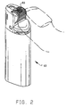
- FIGS. 1 and 2 show lighter 10 according to the present invention as including a slip ring 60 disposed concentrically about the striking wheel.
- the slip ring 60 in FIG. 1 is shown in the ready position.
- the ready position is the position at which the lighter may be activated to produce a spark.
- FIG. 2 shows the lighter 10 of the present invention with the slip ring 60 in the neutral position. When the slip ring 60 is in the neutral position, it cannot be further rotated to create a flame.
- lighter 10 has body 12 with striking wheel assembly 14 disposed between spark wheel supports 15 (shown partially in phantom in FIG. 4) via axle 16.
- Striking wheel assembly 14 is located at the top end of body 12 and comprises turning wheels 18 disposed on each side of rotary sparker 20.
- the two turning wheels 18 and sparker 20 are connected to one another and are mounted coaxially on axle 16.
- Body 12 defines a cylindrical carriage 22 forming a cavity positioned longitudinally and centrally within body 12.
- Flint 24 is disposed within carriage 22, and is urged into frictional contact with the rotary sparker by spring 26.
- Lighter 10 further comprises a valve actuator 28, which is pivotally mounted on body 12 through tabs 30, which are located below axle 16. As shown in FIGS. 6 and 7, valve actuator 28 defines slot 32 at one end for receiving the valve. At the other end of the valve actuator 28 is thumb pad 36. In its middle region, valve actuator 28 defines an opening 37, which allows flint 24 to extend from lighter body 12 through valve actuator 28 to reach rotary sparker 20.
- valve 34 controls the release of fuel from reservoir 42.
- valve 34 is a normally open valve, forced open by the pressure of fuel within reservoir 42.
- valve actuator 28 acts on valve 34 to maintain it in a closed position.
- Compression spring 44 pushes up on a first end of valve actuator 28, forcing the second, opposite end to act downwardly on valve 34 where it extends through slot 32. This pressure maintains the valve in a closed position until thumb pad 36 is sufficiently depressed allowing the stem of valve 34 to move upward and thereby releasing the fuel.
- Second compression spring 38 acts between the valve actuator and valve stem to prevent the release of fuel before the thumb pad 36 is depressed to a sufficiently actuated position.
- a normally closed valve which is forced open by the lifting of the second end of the valve actuator due to depression of the thumb pad may be utilized.
- Lighter 10 also has shield 50 mounted on top of body 12 enclosing the spark wheel supports 15 and around valve 34, as shown in FIG. 5. Shield 50 assists in the generation and maintenance of the flame.
- the lighter 10 of the current invention further includes a slip ring 60 as shown in FIG. 8A.
- Slip ring 60 is mounted concentrically about the striking wheel assembly 14 as is shown in FIGS. 1-5.
- the slip ring 60 comprises a cylindrical sleeve which preferably extends 360° around the striking wheel assembly 14 to form a closed loop.
- the cylindrical sleeve has an elongated channel 70 formed around part of the circumference of the sleeve.
- the elongated channel 70 runs around more than about half of the circumference of the sleeve.
- the exterior surface 68 of the slip ring 60 is preferably serrated in order to make it easier to grip by the user.
- the inner surface 66 of the slip ring 60 is preferably smooth.
- FIG. 8B shows the slip ring 60 in conjunction with the turning wheels 18 and the rotary sparker 20.
- the two turning wheels 18 are placed on the ends of the rotary sparker 20 to form the striking wheel assembly 14.
- the slip ring 60 is placed around the striking wheel assembly 14.
- the slip ring 60 is disposed concentrically about the striking wheel assembly 14.
- a space 41 is shown between the slip ring 60 and the striking wheel assembly 14.
- the space 41 shown in FIG. 3 is greatly exaggerated to demonstrate that a space exists, but the actual space should be suitable to allow the slip ring 60 to slip around the striking wheel assembly 14 to frictionally engage the turning wheels 18 when digital pressure is applied. Since the slip ring 60 entirely surrounds the striking wheel assembly 14, it may only be removed by the user by disassembling the lighter 10.
- the slip ring may rotate freely about the striking wheel assembly 14 in either a forward F or backward B direction of rotation. In order to operate the lighter 10 to produce a spark, digital pressure is applied to the slip ring 60 during rotation of the slip ring 60 in a forward F direction.
- the slip ring 60 frictionally engages the turning wheels 18 and rotates the same to create a spark toward the valve.
- the user digitally rotates the slip ring 60 in concert with the striking wheel assembly 14 to create a spark the user's digit then moves to depress the thumb pad 36 to open the fuel valve 34 in order to produce a flame.
- the slip ring interior surface 66 is preferably smooth and preferably engages only the turning wheels 18 of the striking wheel assembly 14 during rotation.
- materials which may be used for the slip ring 60 include brass, zinc, or plastic. Other embodiments utilizing other materials may also be used and the slip ring 60 of the present invention should not be limited to the above examples.
- slip ring 60 engages the rotary sparker 20.
- Slip ring 60 is preferably the same width as the striking wheel assembly 14.
- the elongated channel 70 is preferably about the same width as the rotary sparker 20.
- the elongated channel must be wide enough to accommodate the width of the flint 24 which is disposed in the cylindrical carriage 22.
- elongated channel 70 is wide enough to accommodate both the cylindrical carriage 22 and the flint 24.
- means for preventing further forward rotation F of the striking wheel assembly 14 after an initial forward rotation F is provided by the first end 72 of the elongated channel 70.
- means for preventing backward rotation of the striking wheel assembly 14 is provided by a second end 74 of the elongated channel 70.
- the slip ring 60 is preferably initially positioned in the ready position as shown in FIG. 1. When pressure is applied to the slip ring 60 to engage the turning wheels 18, the striking wheel assembly 14 rotates in the forward direction F to create a spark toward the valve 34.
- Rotation of the slip ring 60 in the forward direction F is halted when the first end 72 of the elongated channel 70 engages a front surface 90 of the cylindrical carriage 22, which is disposed beneath the rotary sparker 20.
- the slip ring 60 When the slip ring 60 is in this position, it is neutralized. It cannot be rotated further in the forward direction F to create a spark.
- the neutral position of the slip ring 60 is depicted in FIG. 2.
- the slip ring 60 In order to reactivate the striking wheel assembly 14, the slip ring 60 must be rotated in the backward direction B.
- the slip ring 60 further comprises at least one protrusion 80 and preferably a pair of protrusions 80.
- Protrusions 80 extend laterally from the sides of the slip ring and serve to widen the slip ring 60 at their location of placement.
- Protrusions 80 are preferably located along the length of the elongated channel 70 and, most preferably, are located near the first end 72 of the elongated channel 70.
- Protrusions 80 are preferably integrally formed with the slip ring 60.
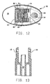
- the body of the lighter includes a pair of spark wheel supports 15 which extend from the top of body 12 of lighter 10 to hold striking wheel assembly 14 in place. Spark wheel supports 15 are shown in FIG. 13 and in phantom in FIGS. 10 and 11. Spark wheel supports 15 are preferably formed integrally with body 12 as is shown in FIG. 13.
- slip ring protrusions 80 engage the inner walls of spark wheel supports 15 as slip ring 60 reaches the neutral position. Protrusions 80 are forced past the front edge of spark wheel supports 15 until they are firmly engaged by the inner walls of the spark wheel supports 15. In order to disengage the protrusions 80, a greater predetermined force must be applied to the slip ring 60 in a backward direction of rotation B.
- Spark wheel supports 15 are preferably composed of a material which is more resiliently deformable than the material of the slip ring protrusions 80 so that the material of the spark wheel supports 15 will be resiliently deformed, e.g., spread apart, to receive the protrusions 80 when force is applied during movement of the slip ring 60 from the ready position to the neutral position.
- the spark wheel supports 15 may include an inner wall cavity 75 for receiving the slip ring protrusions 80.
- slip ring protrusions 80 must pass by an edge of spark wheel supports 15 until they engage the cavity 75.
- a predetermined force must be used to disengage the protrusions from the cavities 75 in the backward direction B.
- the lighter as described above is more difficult to operate and potentially "child-resistant" because generally children under five years of age do not have the needed dexterity to apply digital pressure to rotate the slip ring 60 in concert with the striking wheel assembly 14.
- a child under the age of five may not have the intelligence to determine that the slip ring 60 must be repositioned at the ready position after an attempt to strike the lighter 10 has been made.
Landscapes
- Engineering & Computer Science (AREA)
- Combustion & Propulsion (AREA)
- Mechanical Engineering (AREA)
- General Engineering & Computer Science (AREA)
- Chemical & Material Sciences (AREA)
- Lighters Containing Fuel (AREA)
- Inorganic Insulating Materials (AREA)
- Harvester Elements (AREA)
- Pulleys (AREA)
- Testing Of Balance (AREA)
- Mechanical Operated Clutches (AREA)
- Table Equipment (AREA)
- Diaphragms For Electromechanical Transducers (AREA)
Claims (19)
- Briquet comprenant :caractérisé par un élément annulaire (60) monté de manière à coulisser autour dudit élément producteur d'étincelles (14) et définissant une surface interne (66), ladite surface interne (66) pouvant être mise en prise par friction avec une surface externe dudit élément producteur d'étincelles (14), suite à la pression exercée sur ledit élément annulaire (60), dans lequel l'application d'une pression suffisante du doigt par un utilisateur sur ledit élément annulaire (60) permet à l'utilisateur de faire tourner l'élément producteur d'étincelles (14) afin de produire une étincelle permettant d'enflammer le combustible.un corps de briquet (12) contenant un réservoir de combustible (42) muni d'une valve (34) permettant de libérer le combustible de celui-ci ;un élément producteur d'étincelles (14) qu'un utilisateur peut faire tourner afin de produire une étincelle orientée vers ladite valve (34), ledit élément (14) étant monté sur le corps du briquet (12) ;un actionneur (28) pouvant être abaissé pour actionner ladite valve (34) et libérer ledit combustible ; et
- Briquet selon la revendication 1, dans lequel l'élément annulaire (60) comprend un manchon cylindrique qui s'étend à 360° autour de l'élément producteur d'étincelles (14) pour former une boucle fermée.
- Briquet selon la revendication 2, dans lequel l'élément annulaire (60) possède un canal allongé (70) formé autour d'une partie de la circonférence du manchon.
- Briquet selon la revendication 3, dans lequel le canal allongé (70) entoure plus de la moitié de la circonférence du manchon.
- Briquet selon la revendication 3, dans lequel l'élément annulaire (60) possède une surface extérieure(68) qui est dentelée.
- Briquet selon la revendication 3, dans lequel l'élément producteur d'étincelles (14) comprend :un émetteur d'étincelles (20) rotatif ; etau moins une molette (18) montée coaxialement avec l'émetteur d'étincelles rotatif (20), ledit élément annulaire (60) étant approximativement de la même largeur que l'élément producteur d'étincelles (14), ledit canal allongé (70) étant approximativement de la même largeur que l'émetteur d'étincelles rotatif (20).
- Briquet selon la revendication 6, dans lequel ladite surface interne circulaire (66) dudit élément annulaire (60) met en prise au moins une molette (18).
- Briquet selon la revendication 6, dans lequel :le corps de briquet (12) comprend un élément vertical (22) placé au-dessous de l'émetteur d'étincelles rotatif (20), ledit élément vertical (22) comportant à l'intérieur une pierre à briquet (24) ; etle canal allongé de l'élément annulaire (70) définit une ouverture dans laquelle ladite pierre à briquet est logée (24) par ledit élément producteur d'étincelles (14).
- Briquet selon la revendication 8, dans lequel :une première extrémité (72) du canal allongé (70) met en prise un côté avant de (90) l'élément vertical (22) en position neutre après rotation vers l'avant de l'élément annulaire (60), empêchant de cette façon toute rotation supplémentaire de l'élément annulaire (60) parallèlement à l'élément producteur d'étincelles (14), ledit sens vers l'avant étant le sens de rotation permettant de créer une étincelle orientée vers la valve (34) ; etune seconde extrémité (74) du canal allongé (70) met en prise un côté arrière (92) de l'élément vertical (22) en position armée après que l'élément annulaire (60) soit actionné dans le sens arrière par rapport à l'élément producteur d'étincelles (14) afin de préparer l'élément annulaire (60) à tourner pour créer une étincelle, ledit sens arrière étant opposé audit sens vers l'avant, dans lequel, lorsque l'élément annulaire (60) est tourné depuis la position neutre en position armée, l'élément annulaire (60) peut tourner par rapport à l'élément producteur d'étincelles (14) sans mettre en prise par friction l'élément producteur d'étincelles (14).
- Briquet selon la revendication 9, dans lequel l'élément producteur d'étincelles (14) est monté sur deux supports de molette à étincelles (15), lesdits supports de molette à étincelles (15) étant une extension du corps du briquet (12) et s'étendant longitudinalement depuis le corps (12) au-dessus du réservoir de combustible (42).
- Briquet selon la revendication 10, dans lequel les supports de molette à étincelles (15) font partie intégrante du corps (12) du briquet (10).
- Briquet selon la revendication 10, dans lequel l'élément annulaire (60) comprend en outre au moins une saillie (80) s'étendant latéralement depuis celui-ci, lesdites saillies (80) mettant en prise les supports de molette à étincelles (15) du briquet (10) lorsque l'élément annulaire (60) est mis en position neutre afin d'empêcher la rotation vers l'arrière de l'élément annulaire (60).
- Briquet selon la revendication 12, dans lequel les saillies de l'élément annulaire (80) mettent en prise une paroi interne des supports de la molette à étincelles (15) ledit élément annulaire (60) étant retenu en position fixe lorsque lesdites saillies (80) mettent en prise lesdits supports de molette à étincelles (15), dans lequel une force prédéterminée est nécessaire pour dégager les saillies (80) de la paroi interne des supports de molette à étincelles (15) vers l'arrière.
- Briquet selon la revendication 12, dans lequel les supports de molette à étincelles (15) sont composés d'un matériau qui est plus résilient que le matériau des saillies de l'élément annulaire (80) de sorte que le matériau des supports de la molette à étincelles (15) se déforme de manière résiliente pour permettre aux supports (15) de recevoir les saillies (80) de l'élément annulaire lorsqu'une force est exercée pendant le passage de l'élément annulaire (60) de la position armée à la position neutre.
- Briquet selon la revendication 13, dans lequel les supports de la molette à étincelles (15) possèdent sur une paroi interne une cavité (75), dans laquelle les saillies (80) de l'élément annulaire mettent en prise lesdites cavités (75) après rotation de l'élément annulaire de la position armée à la position neutre, ledit élément annulaire (60) étant retenu en position fixe lorsque lesdites saillies (80) mettent en prise lesdites cavités (75), une force prédéterminée étant nécessaire pour dégager les saillies (80) des cavités (75) vers l'arrière.
- Briquet selon la revendication 9, dans lequel l'élément annulaire (60) comprend en outre deux saillies (80) qui s'étendent latéralement depuis chaque côté de l'élément annulaire (60) à la même section transversale de l'élément annulaire (60), lesdites saillies (80) élargissant ledit élément annulaire (60) à la position transversale choisie.
- Briquet selon la revendication 16, dans lequel la position transversale choisie de positionnement des saillies (80) est située le long du canal allongé (70) à proximité de la première extrémité (72) dudit canal (70).
- Briquet selon la revendication 1, comprenant en outre un dispositif pour limiter la rotation de l'élément annulaire (60) à moins de 360° dans un sens.
- Briquet selon la revendication 18, dans lequel ledit dispositif de limitation de la rotation comprend :un élément vertical (22) s'étendant depuis le corps du briquet (12) vers l'élément producteur d'étincelles (14) ; etune fente (70) ayant des extrémités définies par l'élément annulaire (60), s'étendant partiellement autour de l'élément annulaire (60) dans lequel ledit élément vertical (22) est logé dans ladite fente (70) pour permettre la rotation de l'élément annulaire (60), ladite rotation étant limitée par interférence entre lesdites extrémités de fente (72), (74) et l'élément vertical (22).
Applications Claiming Priority (3)
| Application Number | Priority Date | Filing Date | Title |
|---|---|---|---|
| US609576 | 1990-11-06 | ||
| US08/609,576 US5655902A (en) | 1996-03-01 | 1996-03-01 | Lighter with spark-wheel slip ring |
| PCT/US1997/003014 WO1997032163A1 (fr) | 1996-03-01 | 1997-02-27 | Briquet a bague coulissante pour mollette d'allumage |
Publications (3)
| Publication Number | Publication Date |
|---|---|
| EP0883780A1 EP0883780A1 (fr) | 1998-12-16 |
| EP0883780A4 EP0883780A4 (fr) | 2000-11-15 |
| EP0883780B1 true EP0883780B1 (fr) | 2005-10-05 |
Family
ID=24441372
Family Applications (1)
| Application Number | Title | Priority Date | Filing Date |
|---|---|---|---|
| EP97907884A Expired - Lifetime EP0883780B1 (fr) | 1996-03-01 | 1997-02-27 | Briquet a bague coulissante pour mollette d'allumage |
Country Status (18)
| Country | Link |
|---|---|
| US (1) | US5655902A (fr) |
| EP (1) | EP0883780B1 (fr) |
| JP (1) | JP3850884B2 (fr) |
| KR (1) | KR100441674B1 (fr) |
| CN (1) | CN1114790C (fr) |
| AT (1) | ATE306052T1 (fr) |
| AU (1) | AU714091B2 (fr) |
| BR (1) | BR9707818A (fr) |
| CA (1) | CA2248048C (fr) |
| DE (1) | DE69734314T2 (fr) |
| ES (1) | ES2246508T3 (fr) |
| ID (1) | ID16113A (fr) |
| MY (1) | MY123848A (fr) |
| NO (1) | NO984015L (fr) |
| NZ (1) | NZ331711A (fr) |
| PL (1) | PL184224B1 (fr) |
| RU (1) | RU2175742C2 (fr) |
| WO (1) | WO1997032163A1 (fr) |
Families Citing this family (16)
| Publication number | Priority date | Publication date | Assignee | Title |
|---|---|---|---|---|
| CA2233357A1 (fr) * | 1996-07-30 | 1998-02-05 | Thierry Rogelet | Briquet a gaz |
| US6142768A (en) * | 1999-03-04 | 2000-11-07 | Feng; Xin | Cigarette lighter with security arrangement |
| WO2001013043A1 (fr) * | 1999-08-17 | 2001-02-22 | Polycity Enterprise Limited | Briquet de surete a capuchons de roues rotatifs |
| FR2799531B1 (fr) * | 1999-10-12 | 2002-02-08 | Hameur | Briquet a allumage phyrophorique |
| GB0104622D0 (en) * | 2001-02-24 | 2001-04-11 | Swedish Match Lighters Bv | Child resistant gas lighters |
| US6860733B2 (en) * | 2001-04-20 | 2005-03-01 | L & L Lighter Corp. | Safety gas lighter with a ratchet-pawl mechanism |
| US6695610B2 (en) * | 2001-04-25 | 2004-02-24 | Trend & Aim International Limited | Lighter |
| RU2219438C1 (ru) * | 2002-04-08 | 2003-12-20 | Поцхишвили Давид Вахтангович | Газовая зажигалка с предохранительным устройством |
| GB2390147B (en) * | 2002-06-25 | 2005-12-28 | Top Champion Dev | Hand held lighter |
| GB0328762D0 (en) | 2003-12-11 | 2004-01-14 | Chong Lei H | Hand held lighter |
| US8653942B2 (en) | 2008-08-20 | 2014-02-18 | John Gibson Enterprises, Inc. | Portable biometric lighter |
| US8490631B2 (en) * | 2011-06-27 | 2013-07-23 | Joe Chang | Vaporization lighter |
| CN105910132A (zh) * | 2016-06-16 | 2016-08-31 | 佛山市南海区金沙南沙康业五金厂 | 同轴结构的打火机火轮 |
| US10502419B2 (en) | 2017-09-12 | 2019-12-10 | John Gibson Enterprises, Inc. | Portable biometric lighter |
| CN112443856B (zh) * | 2020-11-04 | 2022-09-13 | 浙江特灵轻工集团有限公司 | 一种便捷式轮转式打火机 |
| CN113108310A (zh) * | 2021-04-28 | 2021-07-13 | 陈佳琪 | 一种打火机的定向组合轮 |
Family Cites Families (15)
| Publication number | Priority date | Publication date | Assignee | Title |
|---|---|---|---|---|
| FR637828A (fr) * | 1927-07-16 | 1928-05-09 | Perfectionnements aux briquets | |
| US1872244A (en) * | 1930-01-03 | 1932-08-16 | Art Metal Works Inc | Pyrophoric pocket lighter |
| CH255523A (de) * | 1947-05-23 | 1948-06-30 | Duerr & Co Aktiengesellschaft | Feuerzeug. |
| US4717335A (en) * | 1986-08-28 | 1988-01-05 | Loveless Guy M | Child resistant lighter |
| US4822276A (en) * | 1988-06-13 | 1989-04-18 | Bisbee Jerry L | Child-proof cigarette lighter |
| US5002482B1 (en) * | 1988-09-02 | 2000-02-29 | Bic Corp | Selectively actuatable lighter |
| US5125829A (en) | 1988-09-02 | 1992-06-30 | Bic Corporation | Bidirectional selectively actuatable lighter |
| CH677021A5 (fr) * | 1988-09-16 | 1991-03-28 | Parnat S A | |
| FR2645626B1 (fr) | 1989-04-07 | 1994-06-03 | Swedish Match Consumer Product | Briquet a gaz |
| US5104313A (en) * | 1989-09-18 | 1992-04-14 | Parnat S.A. | Cigarette lighter |
| FR2671608A1 (fr) | 1991-01-10 | 1992-07-17 | Cricket Sa | Perfectionnement aux briquets a gaz a l'epreuve des enfants. |
| FR2687766A1 (fr) | 1992-02-25 | 1993-08-27 | Cricket Sa | Briquet a gaz a l'epreuve des enfants. |
| JPH0712337A (ja) * | 1993-06-25 | 1995-01-17 | Masayuki Iwabori | ガスライター |
| US5460516A (en) * | 1994-08-24 | 1995-10-24 | Polycity Industrial Ltd. | Safety lighter with locking striker wheel |
| US5547370A (en) * | 1995-09-12 | 1996-08-20 | Hwang; Ing F. | Safety striker wheel assembly for gas lighters |
-
1996
- 1996-03-01 US US08/609,576 patent/US5655902A/en not_active Expired - Lifetime
-
1997
- 1997-02-27 KR KR10-1998-0706852A patent/KR100441674B1/ko not_active Expired - Lifetime
- 1997-02-27 PL PL97328735A patent/PL184224B1/pl not_active IP Right Cessation
- 1997-02-27 CN CN97192732A patent/CN1114790C/zh not_active Expired - Lifetime
- 1997-02-27 AU AU19771/97A patent/AU714091B2/en not_active Expired
- 1997-02-27 NZ NZ331711A patent/NZ331711A/xx unknown
- 1997-02-27 EP EP97907884A patent/EP0883780B1/fr not_active Expired - Lifetime
- 1997-02-27 CA CA002248048A patent/CA2248048C/fr not_active Expired - Lifetime
- 1997-02-27 WO PCT/US1997/003014 patent/WO1997032163A1/fr not_active Ceased
- 1997-02-27 BR BR9707818A patent/BR9707818A/pt not_active IP Right Cessation
- 1997-02-27 RU RU98118021/06A patent/RU2175742C2/ru not_active IP Right Cessation
- 1997-02-27 ES ES97907884T patent/ES2246508T3/es not_active Expired - Lifetime
- 1997-02-27 AT AT97907884T patent/ATE306052T1/de not_active IP Right Cessation
- 1997-02-27 DE DE69734314T patent/DE69734314T2/de not_active Expired - Lifetime
- 1997-02-27 JP JP53108797A patent/JP3850884B2/ja not_active Expired - Lifetime
- 1997-02-28 MY MYPI97000830A patent/MY123848A/en unknown
- 1997-03-03 ID IDP970658A patent/ID16113A/id unknown
-
1998
- 1998-09-01 NO NO984015A patent/NO984015L/no not_active Application Discontinuation
Also Published As
| Publication number | Publication date |
|---|---|
| ATE306052T1 (de) | 2005-10-15 |
| KR100441674B1 (ko) | 2004-11-10 |
| CA2248048A1 (fr) | 1997-09-04 |
| JP2000505542A (ja) | 2000-05-09 |
| DE69734314D1 (de) | 2006-02-16 |
| ID16113A (id) | 1997-09-04 |
| AU1977197A (en) | 1997-09-16 |
| JP3850884B2 (ja) | 2006-11-29 |
| NO984015D0 (no) | 1998-09-01 |
| CN1114790C (zh) | 2003-07-16 |
| MY123848A (en) | 2006-06-30 |
| CN1212754A (zh) | 1999-03-31 |
| CA2248048C (fr) | 2005-06-28 |
| WO1997032163A1 (fr) | 1997-09-04 |
| PL328735A1 (en) | 1999-02-15 |
| RU2175742C2 (ru) | 2001-11-10 |
| PL184224B1 (pl) | 2002-09-30 |
| EP0883780A4 (fr) | 2000-11-15 |
| BR9707818A (pt) | 1999-07-27 |
| AU714091B2 (en) | 1999-12-16 |
| EP0883780A1 (fr) | 1998-12-16 |
| ES2246508T3 (es) | 2006-02-16 |
| KR19990087431A (ko) | 1999-12-27 |
| NZ331711A (en) | 2000-03-27 |
| US5655902A (en) | 1997-08-12 |
| DE69734314T2 (de) | 2006-06-22 |
| NO984015L (no) | 1998-11-02 |
Similar Documents
| Publication | Publication Date | Title |
|---|---|---|
| US5655902A (en) | Lighter with spark-wheel slip ring | |
| EP0961080B1 (fr) | Briquet avec protection | |
| US6123541A (en) | Childproof safety disposable lighter | |
| US5957680A (en) | Lighter having a guard member and cooperating blocking members | |
| US5769098A (en) | Lighter with looped guard | |
| CA2501765C (fr) | Briquet a bague coulissante pour mollette d'allumage | |
| HK1023613B (en) | Lighter with guard | |
| HK1038054B (en) | Lighter having guard member and blocking members | |
| HK1019247A1 (en) | Lighter with spark-wheel slip ring | |
| HK1019247B (en) | Lighter with spark-wheel slip ring | |
| HK1009841B (en) | Lighter with looped guard | |
| HK1011072B (en) | Lighter with guard |
Legal Events
| Date | Code | Title | Description |
|---|---|---|---|
| PUAI | Public reference made under article 153(3) epc to a published international application that has entered the european phase |
Free format text: ORIGINAL CODE: 0009012 |
|
| 17P | Request for examination filed |
Effective date: 19980916 |
|
| AK | Designated contracting states |
Kind code of ref document: A1 Designated state(s): AT BE CH DE DK ES FI FR GB GR IE IT LI LU MC NL PT SE |
|
| A4 | Supplementary search report drawn up and despatched |
Effective date: 20001005 |
|
| AK | Designated contracting states |
Kind code of ref document: A4 Designated state(s): AT BE CH DE DK ES FI FR GB GR IE IT LI LU MC NL PT SE |
|
| 17Q | First examination report despatched |
Effective date: 20040624 |
|
| GRAP | Despatch of communication of intention to grant a patent |
Free format text: ORIGINAL CODE: EPIDOSNIGR1 |
|
| GRAS | Grant fee paid |
Free format text: ORIGINAL CODE: EPIDOSNIGR3 |
|
| GRAA | (expected) grant |
Free format text: ORIGINAL CODE: 0009210 |
|
| AK | Designated contracting states |
Kind code of ref document: B1 Designated state(s): AT BE CH DE DK ES FI FR GB GR IE IT LI LU MC NL PT SE |
|
| PG25 | Lapsed in a contracting state [announced via postgrant information from national office to epo] |
Ref country code: NL Free format text: LAPSE BECAUSE OF FAILURE TO SUBMIT A TRANSLATION OF THE DESCRIPTION OR TO PAY THE FEE WITHIN THE PRESCRIBED TIME-LIMIT Effective date: 20051005 Ref country code: LI Free format text: LAPSE BECAUSE OF FAILURE TO SUBMIT A TRANSLATION OF THE DESCRIPTION OR TO PAY THE FEE WITHIN THE PRESCRIBED TIME-LIMIT Effective date: 20051005 Ref country code: IT Free format text: LAPSE BECAUSE OF FAILURE TO SUBMIT A TRANSLATION OF THE DESCRIPTION OR TO PAY THE FEE WITHIN THE PRESCRIBED TIME-LIMIT;WARNING: LAPSES OF ITALIAN PATENTS WITH EFFECTIVE DATE BEFORE 2007 MAY HAVE OCCURRED AT ANY TIME BEFORE 2007. THE CORRECT EFFECTIVE DATE MAY BE DIFFERENT FROM THE ONE RECORDED. Effective date: 20051005 Ref country code: FI Free format text: LAPSE BECAUSE OF FAILURE TO SUBMIT A TRANSLATION OF THE DESCRIPTION OR TO PAY THE FEE WITHIN THE PRESCRIBED TIME-LIMIT Effective date: 20051005 Ref country code: CH Free format text: LAPSE BECAUSE OF FAILURE TO SUBMIT A TRANSLATION OF THE DESCRIPTION OR TO PAY THE FEE WITHIN THE PRESCRIBED TIME-LIMIT Effective date: 20051005 Ref country code: BE Free format text: LAPSE BECAUSE OF FAILURE TO SUBMIT A TRANSLATION OF THE DESCRIPTION OR TO PAY THE FEE WITHIN THE PRESCRIBED TIME-LIMIT Effective date: 20051005 Ref country code: AT Free format text: LAPSE BECAUSE OF FAILURE TO SUBMIT A TRANSLATION OF THE DESCRIPTION OR TO PAY THE FEE WITHIN THE PRESCRIBED TIME-LIMIT Effective date: 20051005 |
|
| REG | Reference to a national code |
Ref country code: GB Ref legal event code: FG4D |
|
| REG | Reference to a national code |
Ref country code: CH Ref legal event code: EP |
|
| REG | Reference to a national code |
Ref country code: IE Ref legal event code: FG4D |
|
| PG25 | Lapsed in a contracting state [announced via postgrant information from national office to epo] |
Ref country code: SE Free format text: LAPSE BECAUSE OF FAILURE TO SUBMIT A TRANSLATION OF THE DESCRIPTION OR TO PAY THE FEE WITHIN THE PRESCRIBED TIME-LIMIT Effective date: 20060105 Ref country code: GR Free format text: LAPSE BECAUSE OF FAILURE TO SUBMIT A TRANSLATION OF THE DESCRIPTION OR TO PAY THE FEE WITHIN THE PRESCRIBED TIME-LIMIT Effective date: 20060105 Ref country code: DK Free format text: LAPSE BECAUSE OF FAILURE TO SUBMIT A TRANSLATION OF THE DESCRIPTION OR TO PAY THE FEE WITHIN THE PRESCRIBED TIME-LIMIT Effective date: 20060105 |
|
| PGFP | Annual fee paid to national office [announced via postgrant information from national office to epo] |
Ref country code: MC Payment date: 20060201 Year of fee payment: 10 |
|
| REF | Corresponds to: |
Ref document number: 69734314 Country of ref document: DE Date of ref document: 20060216 Kind code of ref document: P |
|
| REG | Reference to a national code |
Ref country code: ES Ref legal event code: FG2A Ref document number: 2246508 Country of ref document: ES Kind code of ref document: T3 |
|
| PGFP | Annual fee paid to national office [announced via postgrant information from national office to epo] |
Ref country code: IE Payment date: 20060227 Year of fee payment: 10 |
|
| NLV1 | Nl: lapsed or annulled due to failure to fulfill the requirements of art. 29p and 29m of the patents act | ||
| PG25 | Lapsed in a contracting state [announced via postgrant information from national office to epo] |
Ref country code: PT Free format text: LAPSE BECAUSE OF FAILURE TO SUBMIT A TRANSLATION OF THE DESCRIPTION OR TO PAY THE FEE WITHIN THE PRESCRIBED TIME-LIMIT Effective date: 20060306 |
|
| PGFP | Annual fee paid to national office [announced via postgrant information from national office to epo] |
Ref country code: LU Payment date: 20060310 Year of fee payment: 10 |
|
| REG | Reference to a national code |
Ref country code: CH Ref legal event code: PL |
|
| ET | Fr: translation filed | ||
| RAP2 | Party data changed (patent owner data changed or rights of a patent transferred) |
Owner name: BIC CORPORATION |
|
| PLBE | No opposition filed within time limit |
Free format text: ORIGINAL CODE: 0009261 |
|
| STAA | Information on the status of an ep patent application or granted ep patent |
Free format text: STATUS: NO OPPOSITION FILED WITHIN TIME LIMIT |
|
| 26N | No opposition filed |
Effective date: 20060706 |
|
| PG25 | Lapsed in a contracting state [announced via postgrant information from national office to epo] |
Ref country code: MC Free format text: LAPSE BECAUSE OF NON-PAYMENT OF DUE FEES Effective date: 20070228 |
|
| REG | Reference to a national code |
Ref country code: IE Ref legal event code: MM4A |
|
| PG25 | Lapsed in a contracting state [announced via postgrant information from national office to epo] |
Ref country code: IE Free format text: LAPSE BECAUSE OF NON-PAYMENT OF DUE FEES Effective date: 20070227 |
|
| PG25 | Lapsed in a contracting state [announced via postgrant information from national office to epo] |
Ref country code: LU Free format text: LAPSE BECAUSE OF NON-PAYMENT OF DUE FEES Effective date: 20070227 |
|
| REG | Reference to a national code |
Ref country code: FR Ref legal event code: PLFP Year of fee payment: 20 |
|
| PGFP | Annual fee paid to national office [announced via postgrant information from national office to epo] |
Ref country code: ES Payment date: 20160226 Year of fee payment: 20 Ref country code: DE Payment date: 20160226 Year of fee payment: 20 |
|
| PGFP | Annual fee paid to national office [announced via postgrant information from national office to epo] |
Ref country code: GB Payment date: 20160226 Year of fee payment: 20 Ref country code: FR Payment date: 20160217 Year of fee payment: 20 |
|
| REG | Reference to a national code |
Ref country code: DE Ref legal event code: R071 Ref document number: 69734314 Country of ref document: DE |
|
| REG | Reference to a national code |
Ref country code: GB Ref legal event code: PE20 Expiry date: 20170226 |
|
| PG25 | Lapsed in a contracting state [announced via postgrant information from national office to epo] |
Ref country code: GB Free format text: LAPSE BECAUSE OF EXPIRATION OF PROTECTION Effective date: 20170226 |
|
| REG | Reference to a national code |
Ref country code: ES Ref legal event code: FD2A Effective date: 20180508 |
|
| PG25 | Lapsed in a contracting state [announced via postgrant information from national office to epo] |
Ref country code: ES Free format text: LAPSE BECAUSE OF EXPIRATION OF PROTECTION Effective date: 20170228 |