EP1640663A2 - Verbesserter Gasbrenner mit nur interner Flamme - Google Patents
Verbesserter Gasbrenner mit nur interner Flamme Download PDFInfo
- Publication number
- EP1640663A2 EP1640663A2 EP05291909A EP05291909A EP1640663A2 EP 1640663 A2 EP1640663 A2 EP 1640663A2 EP 05291909 A EP05291909 A EP 05291909A EP 05291909 A EP05291909 A EP 05291909A EP 1640663 A2 EP1640663 A2 EP 1640663A2
- Authority
- EP
- European Patent Office
- Prior art keywords
- chamber
- burner according
- pot
- burner
- peripheral chamber
- Prior art date
- Legal status (The legal status is an assumption and is not a legal conclusion. Google has not performed a legal analysis and makes no representation as to the accuracy of the status listed.)
- Withdrawn
Links
Images

Classifications
-
- F—MECHANICAL ENGINEERING; LIGHTING; HEATING; WEAPONS; BLASTING
- F23—COMBUSTION APPARATUS; COMBUSTION PROCESSES
- F23D—BURNERS
- F23D14/00—Burners for combustion of a gas, e.g. of a gas stored under pressure as a liquid
- F23D14/02—Premix gas burners, i.e. in which gaseous fuel is mixed with combustion air upstream of the combustion zone
- F23D14/04—Premix gas burners, i.e. in which gaseous fuel is mixed with combustion air upstream of the combustion zone induction type, e.g. Bunsen burner
- F23D14/06—Premix gas burners, i.e. in which gaseous fuel is mixed with combustion air upstream of the combustion zone induction type, e.g. Bunsen burner with radial outlets at the burner head
- F23D14/065—Premix gas burners, i.e. in which gaseous fuel is mixed with combustion air upstream of the combustion zone induction type, e.g. Bunsen burner with radial outlets at the burner head with injector axis inclined to the burner head axis
-
- F—MECHANICAL ENGINEERING; LIGHTING; HEATING; WEAPONS; BLASTING
- F23—COMBUSTION APPARATUS; COMBUSTION PROCESSES
- F23D—BURNERS
- F23D14/00—Burners for combustion of a gas, e.g. of a gas stored under pressure as a liquid
- F23D14/46—Details
- F23D14/70—Baffles or like flow-disturbing devices
Definitions
- the present invention relates to an improved internal only flame gas burner.
- the present invention aims to improve this burner of the prior art so as to eliminate the aforementioned drawbacks.
- the mixture to be burnt arrives in the lower sub-chamber and fills it before escaping to the upper sub-chamber and then to the passages opening into the central zone ("chimney") of the burner.
- the filling of the lower sub-chamber makes it possible to ensure a good distribution and good homogenization of the mixture to be burned around the central zone before this mixture enters this zone.
- the pre-filling of the lower sub-chamber with the mixture to be burned makes it possible to ensure the continuity of the flow of this mixture towards the upper sub-chamber and then towards the passages opening into the central zone, which ultimately allows obtain excellent combustion stability.
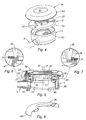
- the gas burner according to the invention comprises a pot 1, a cap 3, an annular baffle 5 and a annular spacer plate 7.
- the pot 1 and the cap 3 are shaped so that once assembled, they define a convergent-divergent pipe 9, or Venturi effect pipe.
- the pot 1 and the cap 3 have a generally circular shape, with the exception of the zone defining the Venturi effect pipe 9.
- This pot and this cap are further shaped so as to define, when they are assembled, on the one hand a central combustion zone 11, and on the other hand a peripheral chamber 13 extending around the central zone 11 and communicating with the Venturi effect pipe 9.
- pot 1 and the cap 3 each comprise a plurality of respective bosses 15a, 15b distributed around the central zone 11.
- bosses are arranged to take the annular spacer plate 7 sandwiched once the burner assembly, and thus define a plurality of passages 17 to establish a communication between the peripheral chamber 13 and the central zone 11 (see Figure 3 ).
- these passages 17 could be formed only in the pot 1, or only in the cap 3, or even in an intermediate piece that would be placed between this pot and this cap.
- annular baffle 5 extends inside the peripheral chamber 13 once the cap 3 is mounted on the pot 1.
- this deflector has an L-shaped section whose branch is fixed to the radially inner wall 19 of the peripheral chamber 13, on the pot 1, and whose other branch is substantially parallel to the general plane of this pot .
- This deflector 5 thus provides a passage 21 with the radially outer wall 23 of the peripheral chamber 13.
- the radial width of the passage 21 is substantially equal to half the radial width of the peripheral chamber 13.
- the baffle 5 thus separates the peripheral chamber 13 into two sub-chambers, namely a lower sub-chamber 25 extending under this baffle, and an upper sub-chamber 27 extending above this deflector.
- the lower sub-chamber 25 communicates with the outlet 29 of the Venturi effect duct 9, and the upper sub-chamber 27 communicates with the passages 17.
- the pot 1 and the cap 3 have a substantially circular shape, so that the deflector 5 has a substantially annular shape.
- deflector 5 would extend from the radially inner wall 19 to the radially outer wall 23, and include a plurality of orifices allowing the communication between the lower sub-chamber 25 and the sub-chamber. superior 27.
- the inlet 29 opens into the peripheral chamber 13 under the deflector 5.
- the hat 3 includes a skirt 33 which bears on the pot 1 and, under this skirt, a ring 35 provided with slots 17 over its entire periphery.
- the radially inner and outer walls of the ring 35 are inscribed on inverted cones, the vertices of which are respectively above and below the burner.
- a housing 39 having in its center an orifice 41 of diameter substantially equal to that of the chimney 11, and at its periphery a folded portion 43 defining a peripheral passage 45 towards the crown 35.
- a baffle 5 of annular shape, separating the lower sub-chamber 25 from the upper sub-chamber 27.
- Figure 7 illustrates the particular case where the deflector 5 is fixed by matting on the shoulder 47, a matted lug 49 being visible in this figure.
- the convergent-divergent duct 9 penetrates slightly inside the lower sub-chamber 25.
- the axes A and A 'of the inner and outer walls of the peripheral chamber 13, respectively, are slightly offset with respect to each other, so that in its portion that is diametrically opposite to the pipe 9, this chamber becomes radially narrower.
- This conduct has the function of ensuring an intimate mixture of the gas leaving the injector with the surrounding air.
- This mixture opens out completely under the baffle 5, and thus begins by filling the lower sub-chamber 25.
- the mixture to burn borrows the passage 21 over the entire periphery of the pot 1, then passes through the upper sub-chamber 27 and the passages 17, thus finally opening into the central zone 11 where it ignites and burns , thus releasing the necessary heat.
- the role of the deflector 5 is to allow a good distribution of the mixture to be burned throughout the peripheral chamber 13 before this mixture reaches the passages 17.
- the prior filling of the lower sub-chamber 25 with the mixture to be burned makes it possible to ensure the continuity of the flow of this mixture towards the upper sub-chamber 27 and then to the passages 17, which makes it possible to obtain excellent combustion stability.
- the operating principle of the burner according to the second embodiment is similar to that of the burner according to the first embodiment: the mixture to be burned arrives inside the sub-chamber lower 25, begins by filling it, then borrows the passage 21 over the entire periphery of the pot 1, then passes through the upper sub-chamber 27 and the passages 17, thus finally opening into the central zone 11 where it ignites and burns, releasing the necessary heat.
- This free space facilitates the installation of a pilot light 51 (see Figure 4), an ignition electrode or any other flame monitoring device such as thermocouples.
- the supports 37 disposed on the skirt 33 of the cap 3 make it possible to keep the casing 39 away from this cap, and thus to establish the peripheral passage 45 between the outside and the crown 35.
- This peripheral passage allows an additional air supply to the flames that exit into the chimney 11 through the passages 17, and thus contributes to the good combustion of the mixture to be burned and, ultimately, to improve the energy efficiency of the burner.
- the housing 39 is removable, and also protects the burner from projections and splashes.
Landscapes
- Engineering & Computer Science (AREA)
- Chemical & Material Sciences (AREA)
- Combustion & Propulsion (AREA)
- Mechanical Engineering (AREA)
- General Engineering & Computer Science (AREA)
- Gas Burners (AREA)
- Evaporation-Type Combustion Burners (AREA)
Applications Claiming Priority (1)
| Application Number | Priority Date | Filing Date | Title |
|---|---|---|---|
| FR0409878A FR2875583B1 (fr) | 2004-09-17 | 2004-09-17 | Bruleur a gaz a flamme interne perfectionne |
Publications (2)
| Publication Number | Publication Date |
|---|---|
| EP1640663A2 true EP1640663A2 (de) | 2006-03-29 |
| EP1640663A3 EP1640663A3 (de) | 2006-04-12 |
Family
ID=34948614
Family Applications (1)
| Application Number | Title | Priority Date | Filing Date |
|---|---|---|---|
| EP05291909A Withdrawn EP1640663A3 (de) | 2004-09-17 | 2005-09-15 | Verbesserter Gasbrenner mit nur interner Flamme |
Country Status (4)
| Country | Link |
|---|---|
| US (1) | US7819657B2 (de) |
| EP (1) | EP1640663A3 (de) |
| CA (1) | CA2520151C (de) |
| FR (1) | FR2875583B1 (de) |
Families Citing this family (11)
| Publication number | Priority date | Publication date | Assignee | Title |
|---|---|---|---|---|
| EP2198199A4 (de) * | 2007-10-10 | 2011-12-14 | Garland Commercial Ind Llc | Venturigehäuseanordnung und verfahren |
| US20090165733A1 (en) * | 2007-12-26 | 2009-07-02 | Ferguson Mark A | Inwardly firing burner and uses thereof |
| JP2011085303A (ja) * | 2009-10-14 | 2011-04-28 | Nichinen:Kk | 内炎式バーナ |
| AU2010324618B2 (en) * | 2009-11-30 | 2014-11-13 | Electrolux Home Products, Inc. | Simmer plate attached to burner |
| USD726898S1 (en) * | 2013-03-13 | 2015-04-14 | John E. Hibbard | Fire lighter |
| US9541294B2 (en) | 2013-08-06 | 2017-01-10 | Whirlpool Corporation | Inner swirling flame gas burner |
| ES2681279T3 (es) | 2015-02-05 | 2018-09-12 | Electrolux Appliances Aktiebolag | Conjunto de quemador de gas |
| US10436451B2 (en) | 2016-10-06 | 2019-10-08 | Whirlpool Corporation | Cap to change inner flame burner to vertical flame |
| US10415824B2 (en) | 2017-05-08 | 2019-09-17 | Haier Us Appliance Solutions, Inc. | Cooktop appliance with a gas burner assembly |
| JP7115969B2 (ja) * | 2018-12-11 | 2022-08-09 | リンナイ株式会社 | コンロ用バーナ並びにガスコンロ |
| US12516808B2 (en) | 2023-01-12 | 2026-01-06 | Haier Us Appliance Solutions, Inc. | Gas burner assembly and cooktop appliance |
Family Cites Families (5)
| Publication number | Priority date | Publication date | Assignee | Title |
|---|---|---|---|---|
| US1653285A (en) * | 1927-05-17 | 1927-12-20 | Louis D Houlis | Gas burner |
| US2044953A (en) * | 1934-03-15 | 1936-06-23 | Herbert R Palmer | Gas burner |
| US3858811A (en) * | 1973-07-02 | 1975-01-07 | Harper Wyman Co | Gas burner |
| FR2848642B1 (fr) * | 2002-12-17 | 2005-08-05 | Service Nat Dit Gaz De France | Bruleur a gaz a flamme interne, de compacite elevee |
| DE10315343A1 (de) * | 2003-04-03 | 2004-10-14 | Isphording Germany Gmbh | Gasbrenner mit Abdeckung |
-
2004
- 2004-09-17 FR FR0409878A patent/FR2875583B1/fr not_active Expired - Fee Related
-
2005
- 2005-09-15 EP EP05291909A patent/EP1640663A3/de not_active Withdrawn
- 2005-09-16 CA CA2520151A patent/CA2520151C/en not_active Expired - Fee Related
- 2005-09-19 US US11/228,320 patent/US7819657B2/en not_active Expired - Fee Related
Also Published As
| Publication number | Publication date |
|---|---|
| CA2520151C (en) | 2013-05-28 |
| CA2520151A1 (en) | 2006-03-17 |
| EP1640663A3 (de) | 2006-04-12 |
| FR2875583B1 (fr) | 2007-04-13 |
| FR2875583A1 (fr) | 2006-03-24 |
| US20060063119A1 (en) | 2006-03-23 |
| US7819657B2 (en) | 2010-10-26 |
Similar Documents
| Publication | Publication Date | Title |
|---|---|---|
| EP0125965B1 (de) | Brenner für gasförmigen Brennstoff mit eingebautem Zünd- und Sicherheitssystem | |
| EP1120603B1 (de) | Gasbrenner mit mehreren Flamenringen | |
| EP1640663A2 (de) | Verbesserter Gasbrenner mit nur interner Flamme | |
| EP0313479B1 (de) | Heizvorrichtung mit katalytischem Brenner | |
| BE719847A (de) | ||
| WO2004046615A1 (fr) | Appareil de chauffage a haut rendement | |
| EP0751352B1 (de) | Auf einer Einspritzdüse zentrierter Kochbrenner | |
| FR2697320A1 (fr) | Brûleur à gaz extra-plat à système de sécurité destiné particulièrement aux appareils à cuisiner à usage domestique. | |
| BE902029A (fr) | Bruleur a gaz pour fourneaux et plans de cuisson en general. | |
| FR3013422A1 (fr) | Poele a granules et son procede de fonctionnement | |
| EP1406043A1 (de) | Gasbrenner | |
| FR2783040A1 (fr) | Bruleur a gaz pour le chauffage et/ou la cuisson d'aliments | |
| FR2642148A1 (fr) | Bruleur multi-gaz avec reglage de l'injecteur par le dessus | |
| CA3146685A1 (fr) | Bruleur modulaire et four comprenant ce bruleur | |
| FR3078384A1 (fr) | Chambre de combustion a fond de chambre double | |
| FR2619894A1 (fr) | Plaque de cuisson comportant des bruleurs a gaz a rayonnement et une plaque de revetement en vitrocerame, notamment pour caravanes | |
| EP4519605B1 (de) | Oberflächenverbrennbarer und explosionsgeschützter gasbrenner | |
| EP0064725B1 (de) | Gasbrenner, insbesondere zum Kochen bei niedriger Temperatur | |
| EP0883782B1 (de) | Heizgerät | |
| FR2546273A1 (fr) | Bruleur-torche a premelange d'air et de gaz | |
| FR2770620A1 (fr) | Bruleur a gaz pour cuisiniere ou plan de cuisson | |
| BE679732A (de) | ||
| EP0223634A1 (de) | Gasbrenner der Gas/Luftvormischungsbauart | |
| FR3128511A1 (fr) | Dispositif d’habillage pour conduit de raccordement et installation de chauffage comprenant un tel dispositif d’habillage | |
| FR2483569A1 (fr) | Appareil de combustion autoregule |
Legal Events
| Date | Code | Title | Description |
|---|---|---|---|
| PUAI | Public reference made under article 153(3) epc to a published international application that has entered the european phase |
Free format text: ORIGINAL CODE: 0009012 |
|
| PUAL | Search report despatched |
Free format text: ORIGINAL CODE: 0009013 |
|
| AK | Designated contracting states |
Kind code of ref document: A2 Designated state(s): AT BE BG CH CY CZ DE DK EE ES FI FR GB GR HU IE IS IT LI LT LU LV MC NL PL PT RO SE SI SK TR |
|
| AX | Request for extension of the european patent |
Extension state: AL BA HR MK YU |
|
| AK | Designated contracting states |
Kind code of ref document: A3 Designated state(s): AT BE BG CH CY CZ DE DK EE ES FI FR GB GR HU IE IS IT LI LT LU LV MC NL PL PT RO SE SI SK TR |
|
| AX | Request for extension of the european patent |
Extension state: AL BA HR MK YU |
|
| 17P | Request for examination filed |
Effective date: 20060919 |
|
| 17Q | First examination report despatched |
Effective date: 20061106 |
|
| AKX | Designation fees paid |
Designated state(s): DE ES FR GB IT NL |
|
| RAP1 | Party data changed (applicant data changed or rights of an application transferred) |
Owner name: GDF SUEZ Owner name: LEMDYS |
|
| RAP1 | Party data changed (applicant data changed or rights of an application transferred) |
Owner name: GDF SUEZ Owner name: LEMDYS |
|
| STAA | Information on the status of an ep patent application or granted ep patent |
Free format text: STATUS: THE APPLICATION IS DEEMED TO BE WITHDRAWN |
|
| 18D | Application deemed to be withdrawn |
Effective date: 20150630 |