EP0884112A2 - Aluminium-Harz-Verbundprofile, wärmedämmende Aluminium Profile und Verfahren und Vorrichtung zu deren Herstellung - Google Patents
Aluminium-Harz-Verbundprofile, wärmedämmende Aluminium Profile und Verfahren und Vorrichtung zu deren Herstellung Download PDFInfo
- Publication number
- EP0884112A2 EP0884112A2 EP98110476A EP98110476A EP0884112A2 EP 0884112 A2 EP0884112 A2 EP 0884112A2 EP 98110476 A EP98110476 A EP 98110476A EP 98110476 A EP98110476 A EP 98110476A EP 0884112 A2 EP0884112 A2 EP 0884112A2
- Authority
- EP
- European Patent Office
- Prior art keywords
- profile
- resin
- aluminum profile
- recess
- discharge treatment
- Prior art date
- Legal status (The legal status is an assumption and is not a legal conclusion. Google has not performed a legal analysis and makes no representation as to the accuracy of the status listed.)
- Granted
Links
Images




Classifications
-
- E—FIXED CONSTRUCTIONS
- E06—DOORS, WINDOWS, SHUTTERS, OR ROLLER BLINDS IN GENERAL; LADDERS
- E06B—FIXED OR MOVABLE CLOSURES FOR OPENINGS IN BUILDINGS, VEHICLES, FENCES OR LIKE ENCLOSURES IN GENERAL, e.g. DOORS, WINDOWS, BLINDS, GATES
- E06B3/00—Window sashes, door leaves, or like elements for closing wall or like openings; Layout of fixed or moving closures, e.g. windows in wall or like openings; Features of rigidly-mounted outer frames relating to the mounting of wing frames
- E06B3/04—Wing frames not characterised by the manner of movement
- E06B3/06—Single frames
- E06B3/08—Constructions depending on the use of specified materials
- E06B3/20—Constructions depending on the use of specified materials of plastics
- E06B3/22—Hollow frames
- E06B3/221—Hollow frames with the frame member having local reinforcements in some parts of its cross-section or with a filled cavity
-
- B—PERFORMING OPERATIONS; TRANSPORTING
- B29—WORKING OF PLASTICS; WORKING OF SUBSTANCES IN A PLASTIC STATE IN GENERAL
- B29C—SHAPING OR JOINING OF PLASTICS; SHAPING OF MATERIAL IN A PLASTIC STATE, NOT OTHERWISE PROVIDED FOR; AFTER-TREATMENT OF THE SHAPED PRODUCTS, e.g. REPAIRING
- B29C44/00—Shaping by internal pressure generated in the material, e.g. swelling or foaming ; Producing porous or cellular expanded plastics articles
- B29C44/02—Shaping by internal pressure generated in the material, e.g. swelling or foaming ; Producing porous or cellular expanded plastics articles for articles of definite length, i.e. discrete articles
- B29C44/12—Incorporating or moulding on preformed parts, e.g. inserts or reinforcements
- B29C44/129—Enhancing adhesion to the preformed part using an interlayer
-
- B—PERFORMING OPERATIONS; TRANSPORTING
- B29—WORKING OF PLASTICS; WORKING OF SUBSTANCES IN A PLASTIC STATE IN GENERAL
- B29C—SHAPING OR JOINING OF PLASTICS; SHAPING OF MATERIAL IN A PLASTIC STATE, NOT OTHERWISE PROVIDED FOR; AFTER-TREATMENT OF THE SHAPED PRODUCTS, e.g. REPAIRING
- B29C39/00—Shaping by casting, i.e. introducing the moulding material into a mould or between confining surfaces without significant moulding pressure; Apparatus therefor
- B29C39/14—Shaping by casting, i.e. introducing the moulding material into a mould or between confining surfaces without significant moulding pressure; Apparatus therefor for making articles of indefinite length
- B29C39/18—Shaping by casting, i.e. introducing the moulding material into a mould or between confining surfaces without significant moulding pressure; Apparatus therefor for making articles of indefinite length incorporating preformed parts or layers, e.g. casting around inserts or for coating articles
-
- B—PERFORMING OPERATIONS; TRANSPORTING
- B29—WORKING OF PLASTICS; WORKING OF SUBSTANCES IN A PLASTIC STATE IN GENERAL
- B29C—SHAPING OR JOINING OF PLASTICS; SHAPING OF MATERIAL IN A PLASTIC STATE, NOT OTHERWISE PROVIDED FOR; AFTER-TREATMENT OF THE SHAPED PRODUCTS, e.g. REPAIRING
- B29C44/00—Shaping by internal pressure generated in the material, e.g. swelling or foaming ; Producing porous or cellular expanded plastics articles
- B29C44/02—Shaping by internal pressure generated in the material, e.g. swelling or foaming ; Producing porous or cellular expanded plastics articles for articles of definite length, i.e. discrete articles
- B29C44/12—Incorporating or moulding on preformed parts, e.g. inserts or reinforcements
- B29C44/1228—Joining preformed parts by the expanding material
-
- B—PERFORMING OPERATIONS; TRANSPORTING
- B29—WORKING OF PLASTICS; WORKING OF SUBSTANCES IN A PLASTIC STATE IN GENERAL
- B29C—SHAPING OR JOINING OF PLASTICS; SHAPING OF MATERIAL IN A PLASTIC STATE, NOT OTHERWISE PROVIDED FOR; AFTER-TREATMENT OF THE SHAPED PRODUCTS, e.g. REPAIRING
- B29C44/00—Shaping by internal pressure generated in the material, e.g. swelling or foaming ; Producing porous or cellular expanded plastics articles
- B29C44/34—Auxiliary operations
- B29C44/36—Feeding the material to be shaped
- B29C44/38—Feeding the material to be shaped into a closed space, i.e. to make articles of definite length
- B29C44/388—Feeding the material to be shaped into a closed space, i.e. to make articles of definite length into moving moulds
-
- B—PERFORMING OPERATIONS; TRANSPORTING
- B29—WORKING OF PLASTICS; WORKING OF SUBSTANCES IN A PLASTIC STATE IN GENERAL
- B29C—SHAPING OR JOINING OF PLASTICS; SHAPING OF MATERIAL IN A PLASTIC STATE, NOT OTHERWISE PROVIDED FOR; AFTER-TREATMENT OF THE SHAPED PRODUCTS, e.g. REPAIRING
- B29C59/00—Surface shaping of articles, e.g. embossing; Apparatus therefor
- B29C59/10—Surface shaping of articles, e.g. embossing; Apparatus therefor by electric discharge treatment
- B29C59/103—Surface shaping of articles, e.g. embossing; Apparatus therefor by electric discharge treatment of profiled articles, e.g. hollow or tubular articles
-
- B—PERFORMING OPERATIONS; TRANSPORTING
- B32—LAYERED PRODUCTS
- B32B—LAYERED PRODUCTS, i.e. PRODUCTS BUILT-UP OF STRATA OF FLAT OR NON-FLAT, e.g. CELLULAR OR HONEYCOMB, FORM
- B32B15/00—Layered products comprising a layer of metal
- B32B15/04—Layered products comprising a layer of metal comprising metal as the main or only constituent of a layer, which is next to another layer of the same or of a different material
- B32B15/08—Layered products comprising a layer of metal comprising metal as the main or only constituent of a layer, which is next to another layer of the same or of a different material of synthetic resin
-
- B—PERFORMING OPERATIONS; TRANSPORTING
- B32—LAYERED PRODUCTS
- B32B—LAYERED PRODUCTS, i.e. PRODUCTS BUILT-UP OF STRATA OF FLAT OR NON-FLAT, e.g. CELLULAR OR HONEYCOMB, FORM
- B32B15/00—Layered products comprising a layer of metal
- B32B15/20—Layered products comprising a layer of metal comprising aluminium or copper
-
- E—FIXED CONSTRUCTIONS
- E06—DOORS, WINDOWS, SHUTTERS, OR ROLLER BLINDS IN GENERAL; LADDERS
- E06B—FIXED OR MOVABLE CLOSURES FOR OPENINGS IN BUILDINGS, VEHICLES, FENCES OR LIKE ENCLOSURES IN GENERAL, e.g. DOORS, WINDOWS, BLINDS, GATES
- E06B3/00—Window sashes, door leaves, or like elements for closing wall or like openings; Layout of fixed or moving closures, e.g. windows in wall or like openings; Features of rigidly-mounted outer frames relating to the mounting of wing frames
- E06B3/04—Wing frames not characterised by the manner of movement
- E06B3/06—Single frames
- E06B3/08—Constructions depending on the use of specified materials
- E06B3/12—Constructions depending on the use of specified materials of metal
- E06B3/14—Constructions depending on the use of specified materials of metal of special cross-section
- E06B3/16—Hollow frames of special construction, e.g. made of folded sheet metal or of two or more section parts connected together
- E06B3/163—Hollow frames of special construction, e.g. made of folded sheet metal or of two or more section parts connected together with a filled cavity
-
- E—FIXED CONSTRUCTIONS
- E06—DOORS, WINDOWS, SHUTTERS, OR ROLLER BLINDS IN GENERAL; LADDERS
- E06B—FIXED OR MOVABLE CLOSURES FOR OPENINGS IN BUILDINGS, VEHICLES, FENCES OR LIKE ENCLOSURES IN GENERAL, e.g. DOORS, WINDOWS, BLINDS, GATES
- E06B3/00—Window sashes, door leaves, or like elements for closing wall or like openings; Layout of fixed or moving closures, e.g. windows in wall or like openings; Features of rigidly-mounted outer frames relating to the mounting of wing frames
- E06B3/04—Wing frames not characterised by the manner of movement
- E06B3/06—Single frames
- E06B3/24—Single frames specially adapted for double glazing
-
- E—FIXED CONSTRUCTIONS
- E06—DOORS, WINDOWS, SHUTTERS, OR ROLLER BLINDS IN GENERAL; LADDERS
- E06B—FIXED OR MOVABLE CLOSURES FOR OPENINGS IN BUILDINGS, VEHICLES, FENCES OR LIKE ENCLOSURES IN GENERAL, e.g. DOORS, WINDOWS, BLINDS, GATES
- E06B3/00—Window sashes, door leaves, or like elements for closing wall or like openings; Layout of fixed or moving closures, e.g. windows in wall or like openings; Features of rigidly-mounted outer frames relating to the mounting of wing frames
- E06B3/04—Wing frames not characterised by the manner of movement
- E06B3/263—Frames with special provision for insulation
- E06B3/267—Frames with special provision for insulation with insulating elements formed in situ
-
- B—PERFORMING OPERATIONS; TRANSPORTING
- B05—SPRAYING OR ATOMISING IN GENERAL; APPLYING FLUENT MATERIALS TO SURFACES, IN GENERAL
- B05D—PROCESSES FOR APPLYING FLUENT MATERIALS TO SURFACES, IN GENERAL
- B05D2202/00—Metallic substrate
- B05D2202/20—Metallic substrate based on light metals
- B05D2202/25—Metallic substrate based on light metals based on Al
-
- B—PERFORMING OPERATIONS; TRANSPORTING
- B29—WORKING OF PLASTICS; WORKING OF SUBSTANCES IN A PLASTIC STATE IN GENERAL
- B29L—INDEXING SCHEME ASSOCIATED WITH SUBCLASS B29C, RELATING TO PARTICULAR ARTICLES
- B29L2031/00—Other particular articles
- B29L2031/001—Profiled members, e.g. beams, sections
- B29L2031/003—Profiled members, e.g. beams, sections having a profiled transverse cross-section
- B29L2031/005—Profiled members, e.g. beams, sections having a profiled transverse cross-section for making window frames
-
- Y—GENERAL TAGGING OF NEW TECHNOLOGICAL DEVELOPMENTS; GENERAL TAGGING OF CROSS-SECTIONAL TECHNOLOGIES SPANNING OVER SEVERAL SECTIONS OF THE IPC; TECHNICAL SUBJECTS COVERED BY FORMER USPC CROSS-REFERENCE ART COLLECTIONS [XRACs] AND DIGESTS
- Y10—TECHNICAL SUBJECTS COVERED BY FORMER USPC
- Y10T—TECHNICAL SUBJECTS COVERED BY FORMER US CLASSIFICATION
- Y10T428/00—Stock material or miscellaneous articles
- Y10T428/31504—Composite [nonstructural laminate]
- Y10T428/31551—Of polyamidoester [polyurethane, polyisocyanate, polycarbamate, etc.]
- Y10T428/31605—Next to free metal
-
- Y—GENERAL TAGGING OF NEW TECHNOLOGICAL DEVELOPMENTS; GENERAL TAGGING OF CROSS-SECTIONAL TECHNOLOGIES SPANNING OVER SEVERAL SECTIONS OF THE IPC; TECHNICAL SUBJECTS COVERED BY FORMER USPC CROSS-REFERENCE ART COLLECTIONS [XRACs] AND DIGESTS
- Y10—TECHNICAL SUBJECTS COVERED BY FORMER USPC
- Y10T—TECHNICAL SUBJECTS COVERED BY FORMER US CLASSIFICATION
- Y10T428/00—Stock material or miscellaneous articles
- Y10T428/31504—Composite [nonstructural laminate]
- Y10T428/31678—Of metal
-
- Y—GENERAL TAGGING OF NEW TECHNOLOGICAL DEVELOPMENTS; GENERAL TAGGING OF CROSS-SECTIONAL TECHNOLOGIES SPANNING OVER SEVERAL SECTIONS OF THE IPC; TECHNICAL SUBJECTS COVERED BY FORMER USPC CROSS-REFERENCE ART COLLECTIONS [XRACs] AND DIGESTS
- Y10—TECHNICAL SUBJECTS COVERED BY FORMER USPC
- Y10T—TECHNICAL SUBJECTS COVERED BY FORMER US CLASSIFICATION
- Y10T428/00—Stock material or miscellaneous articles
- Y10T428/31504—Composite [nonstructural laminate]
- Y10T428/31678—Of metal
- Y10T428/31681—Next to polyester, polyamide or polyimide [e.g., alkyd, glue, or nylon, etc.]
-
- Y—GENERAL TAGGING OF NEW TECHNOLOGICAL DEVELOPMENTS; GENERAL TAGGING OF CROSS-SECTIONAL TECHNOLOGIES SPANNING OVER SEVERAL SECTIONS OF THE IPC; TECHNICAL SUBJECTS COVERED BY FORMER USPC CROSS-REFERENCE ART COLLECTIONS [XRACs] AND DIGESTS
- Y10—TECHNICAL SUBJECTS COVERED BY FORMER USPC
- Y10T—TECHNICAL SUBJECTS COVERED BY FORMER US CLASSIFICATION
- Y10T428/00—Stock material or miscellaneous articles
- Y10T428/31504—Composite [nonstructural laminate]
- Y10T428/31678—Of metal
- Y10T428/31692—Next to addition polymer from unsaturated monomers
- Y10T428/31699—Ester, halide or nitrile of addition polymer
Definitions
- This invention relates to a technique for the union between an aluminum profile and a resin material, and more particularly to resin-composite aluminum profiles having a resin material joined to an aluminum profile, especially heat insulating aluminum profiles having the joined parts of opposed lateral sheet members of an aluminum profile formed with a resin material, a method for the production of the profiles, and an apparatus, particularly a discharge treatment apparatus to be used for the production of the profiles.
- aluminum profile[s] is used herein to express the shapes or sections of aluminum or an aluminum alloy shaped into a continuous form (hereinafter referred to simply as “profile[s]”) and the term “resin-composite aluminum profile[s]” is used to express the concept embracing the heat insulating aluminum shapes or sections (hereinafter referred to simply as “heat insulating profile[s]”).
- the composite profiles having a resin material joined to the surface or recess of a profile have been used in various technical fields because they are light and excellent in durability, strength, or the like.
- sashes which are provided on either of the exterior and the interior side of building with a double paper sliding door disposing part have been disseminating with a view to affording insulation from heat, abating noise, and preventing dew condensation.
- the heat insulating profiles are used in the frames of such sashes.
- the heat insulating profile is provided between the opposed lateral sheet members thereof with a joined part formed of synthetic resin and, in this structure, allowed to have the opposed lateral sheet members integrally joined by the adhesive force of the resin material and, owing to the intervention of the resin material between the opposed sheet members, enabled to manifest the functions of affording insulation from heat, abating noise, and preventing dew condensation.
- resin material mentioned above generally a foamable hard polyurethane resin is used as taught in published Japanese Patent Application, KOKAI (Early Publication) No. 54-19,537, for example.
- a urethane resin material is injected to capacity into a recess provided between the coated, opposed lateral sheet members of a profile and wished to be packed with a resin and thereafter the portion of the profile which forms the recess is cut so that the opposed lateral sheet members are joined to each other solely with the urethane resin.
- the resin and the profile are liable to peel off each other. Once the separation of this sort occurs, the profile has the problem of emitting a squeak when deformed under an external force and betraying deficiency in strength as well.
- the heat insulating profile entails the problems of durability such as causing shrinkage of the urethane resin after a protracted use, tending to induce the phenomenon of giving rise to a step in the butt end (discernible by a test of repeating cycles of cooling and heating), and possibly inserting a crack in the face of union and inducing leakage of rain water through the crack.
- an object of the present invention to develop a technique for improving the adhesive force to be generated between a profile and a resin by a relatively simple and inexpensive method and, therefore, allow manufacture of the composite profiles or heat insulating profiles having a profile and a resin joined fast to each other at low cost with high efficiency.
- the present invention has for an object thereof the provision of the composite profiles, especially the heat insulating profiles, which allow easy treatment of the recess wished to be filled with resin even when a hole-forming part for screw is protruded into the recess, produce high adhesive strength between a profile and a resin, prevent the profile from emitting a squeak even on exposure to an external force, exhibit high strength, offer strong resistance to the shrinkage of resin, entails virtually no phenomenon of giving rise to a step in the butt end, and excels in durability enough to withstand a protracted use and a highly efficient method for the manufacture thereof.
- a further object of the present invention is to develop an apparatus, particularly an electrode for a discharge treatment apparatus, which can be advantageously used for the method described above.
- the present invention in the basic aspect thereof provides a method for the production of a resin-composite profile characterized by performing a discharge treatment on the surface of the portion of a coated profile destined for union with resin and joining a resin material to the discharge treated portion.
- the discharge treatment is performed on the inner surface of the recess and the discharge treated recess is filled with the resin material.
- the profile to be effectively used for the present invention may be a profile having a coating film formed by a coating treatment on the surface of a profile of aluminum or an aluminum alloy, generally an extruded profile, or a profile having formed thereon a composite film comprising an anodic oxide film, colored oxide film, or chemical conversion film and a coating film superposed thereon.
- a profile furnished on the surface thereof with a coating film is invariably usable for the present invention.
- the coating treatment involved herein may be performed by any of the heretofore known methods such as, for example, electrodeposition coating, immersion coating, and electrostatic coating.
- a method for the production of a heat insulating profile characterized by performing a discharge treatment on the inner surface of a recess disposed between opposed lateral sheet members of a coated profile and intended to be filled with resin, filling a resin material in the discharge treated recess, and then cutting the portion of the profile forming the recess, thereby obtaining a heat insulating profile having the opposed lateral sheet members integrally joined to each other with the resin material filled as described above.
- the discharge treatment and the packing of resin material are performed on the interior of one of the recesses and then the portion of the profile forming the other recess is cut when the portion of the profile forming the recess mentioned above is subsequently cut, a resin sheet is superposed on the cut portion of the other recess to occlude this cut portion, and subsequently the discharge treatment and the packing of resin material are performed on the interior of the other recess.
- the present invention further provides an apparatus for the production of the composite profile or heat insulating profile mentioned above, characterized by being furnished at least with means for conveying a coated profile, discharge means disposed so as to be freely approximated to the profile on the conveying means for the purpose of performing a discharge treatment on the profile in motion on the conveying means, and resin filling means disposed on the downstream side of the discharge means and adapted to be freely approximated to the profile on the conveying means.
- the apparatus for the production of a heat insulating profile is furnished on the downstream side of the resin filling means with a device for cutting the resin-filled recess portion of the profile similarly in the standard apparatus for production and, when the profile has at least two recesses, furnished further with a device for sealing the cut recess portion with a resin sheet.
- the present invention further provides an electrode for the discharge treatment of a profile, which can be used advantageously for the discharge treatment mentioned above.
- the electrode comprises a base part shaped like a rod or a plate and connected to a high-voltage power source and a projecting part adapted to protrude laterally from the lower terminal portion of the base part and confront the inner surface of a recess to be treated when the projecting part is inserted into the recess of a profile.
- the projecting part comprises a plurality of linear materials having the upper ends thereof bundled and fixed to the lower terminal portion of the base part.
- the use of the apparatus of the present invention mentioned above, particularly the use of the aforementioned electrode for the discharge treatment, allows the discharge treatment to be performed effectively and continuously on the part of the surface of a coating film of the profile which is wished to be treated and results in improving the productivity of the composite profile and the heat insulating profile.
- the production of a composite profile or heat insulating profile according to the present invention is basically characterized by increasing the adhesive strength between resin and a profile by performing a discharge treatment in advance on the coated surface of the resin-joining portion of a profile or the coated inner surface of a recess formed in the profile and destined to be packed with resin.
- the resin material to be used for filling is such a resin as a urethane resin which is formed of isocyanate and polyol and therefore possessed of a functional group capable of reacting with the free functional group to be formed on the surface of a coating film in consequence of the discharge treatment mentioned above, the reaction between these functional groups exalts the adhesive strength to a very high extent.
- the coating film on the surface of the profile is only required to be capable of forming such a hydrophilic functional group as mentioned above in consequence of the discharge treatment.
- the coating films which result from applying acrylic resin coating material, acryl-melamine resin coating material, polyester coating material, polyurethane coating material, melamine resin coating material, acryl-silicone resin coating material (having two or more fluorine atoms bound to a silane group) by such a coating method as electrodeposition coating, immersion coating, or electrostatic coating may be cited.
- heat insulating resin such as, for example, urethane resins or epoxy resins of the cold-setting type, or acrylic resins of the photo-setting type can be used.
- the urethane resins which possess suitable flexibility at normal room temperatures or in a range of low temperatures and retain strength and suitable rigidity in a range of high temperatures prove to be particularly advantageous.
- a method for performing the discharge treatment (1) a method which comprises performing a corona discharge on a given coating film at normal room temperature under normal pressure thereby effecting a surface treatment of the coating film (corona discharge treatment), (2) a method which comprises performing a glow discharge on a given coating film in a vacuum thereby treating the surface of the coating film (ionic treatment), and (3) a method which comprises sealing a given coating film in a vacuum containing a trace quantity of a monomer and an inert gas and performing a glow discharge on the coating film to effect a surface modification of the coating film (plasma treatment) may be cited.
- These methods are invariably capable of modifying the surface of the coating film of a profile by virtue of electric energy.
- the method of corona discharge treatment which can be carried out rather simply at normal room temperature under normal pressure at a low cost proves to be particularly advantageous.
- the treating devices available for the corona discharge treatment are broadly known in three types, i.e. a spark gap system, a vacuum tube system, and a solid state system.
- a spark gap system i.e. a spark gap system
- a vacuum tube system i.e. a vacuum tube system
- a solid state system i.e. a solid state system.
- any of these systems can be effectively adopted.
- the conditions for the discharge treatment are preferred to be set such that the surface of the coating film of a discharge treated profile registers a surface tension of not less than 45 dyn/cm or causes 5 ⁇ l of water drops poured thereon to spread over an area of not less than 3.5 cm, preferably not less than 3.7 cm in diameter.
- These conditions can be adjusted, for example, by suitably setting the speed of conveyance of the profile or the magnitude of discharge voltage or other discharge conditions.
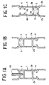
- Figs. 1A through 1F illustrate one example of the process to be performed when the method of the present invention is applied to the production of a heat insulating profile.
- an electrode 20 for discharge treatment is inserted into one (3) of two resin filling recesses 3 and 4 (hereinafter referred to as "pouring pockets") disposed between opposed lateral sheet members 2a and 2b of a coated profile 1 in such a manner as to interconnect the sheet members 2a and 2b and it is operated therein to perform a discharge treatment on the inner surface of the pouring pocket 3.
- a resin 5 is poured into the discharge treated pouring pocket 3 and allowed to set therein.
- the profile 1 is turned upside down.
- part of the bottom portion 3a of the other pouring pocket 3 is likewise cut.
- the cutting tool may be inserted through an opening on the bottom portion 3a side and manipulated to cut part of the bottom portion 3a.
- a resin sheet 6 is applied fast to the bottom portion 4a of the other pouring pocket 4 so as to cover the cut opening part 4b.
- Various kinds of synthetic resin sheet may be used as the resin sheet 6.
- This resin sheet 6 is preferred to be a sheet of polyester which possesses fair rigidity and forms a free hydrophilic functional group like -COOH in consequence of discharge treatment.
- the thickness of this resin sheet 6 which is proper for the present invention generally falls in the approximate range of 150 - 180 ⁇ m, depending on the kind of the resin sheet to be used.
- the electrode 20 for discharge treatment is inserted into the other pouring pocket 4 and operated to perform a discharge treatment on the surfaces of the pouring pocket 4 and resin sheet 6.
- the process of discharge treatment may be performed first on the upper and lower pouring pockets 3 and 4 (by performing the discharge treatment on the pouring pocket 3 as illustrated in Fig. 1A, then turning the profile 1 upside down, and subsequently performing the discharge treatment on the pouring pocket 4, for example) and thereafter the steps of Figs. 1B, 1C, 1D, and 1F may be carried out.
- Fig. 2 illustrates part of one example of an aluminum sash formed by assembling heat insulating profiles of various structures produced by the method described above.
- the reference numeral 11 represents an outer meeting stile, 12 a lower rail, 13 a lower frame, and 14 a vertical frame, which are invariably heat insulating structures using the resin 5.
- the reference numerals 15a and 15b each represent a double-wall glass. Owing to the structure of this sort, the produced aluminum sash excels in the ability to offer insulation from heat, the ability to prevent dew condensation, and the durability. Further, since the component heat insulating profiles excel in adhesive strength with the resin, the aluminum sash will not emit a squeak even when it is accidentally exposed to an external force.
- Fig. 3 is a fragmentary cross section illustrating one example of a heat insulating profile 10a having a hole-forming part 8 for screw protruded into a pouring pocket 7 similarly in the lower rail 12 illustrated in Fig. 2. According to the method of the present invention, the discharge treatment and the filling of resin can be easily performed even on the pouring pocket 7 which is furnished with the hole-forming part 8 for screw.
- a cut part 7b of a bottom portion 7a of the pouring pocket 7 in this structure is generally held to be one of the basal parts of the hole-forming part 8 for screw.
- Fig. 4 illustrates one example of the insertion of a discharge treatment electrode 20a into a pouring pocket 9 of the lower frame 13 illustrated in Fig. 2.
- the discharge treatment electrode 20a is depicted herein as being lined with a silicone rubber 21.
- the electrode to be used in the discharge treatment can be made in various shapes as illustrated in Fig. 5 through Fig. 9.
- Fig. 5 illustrates an electrode 20b shaped like a round rod and Fig. 6 illustrates an electrode 20c shaped like a plate. These electrodes each have a high-voltage lead wire 23 set in place with a screw in the upper part thereof.
- the reference numeral 22 represents a porcelain insulator.
- Fig. 7 illustrates an electrode 20d shaped like a disc. The electrode 20d is rotatably attached to a bracket 25 through the medium of a pin 24 having the high-voltage lead wire 23 connected thereto.
- An electrode 20e illustrated in Fig. 8 has a structure such that a projecting part 27 whose cross section laterally diverges in the shape of the letter V is fixed to the lower terminal portion of a rodlike base part 26 having the high-voltage lead wire 23 connected thereto
- This projecting part 27 brings about such advantages as imparting elasticity to the relevant portion, facilitating the insertion of the electrode into the pouring pocket of the profile in motion on the conveying means, allaying the concentration of discharge on the claws (represented by the reference numeral 29 in Fig. 4, for example) protruding into the pouring pocket, and ensuring easy discharge throughout the entire inner surface of the pouring pocket.
- aluminum, stainless steel, iron, or copper may be used either in a form devoid of a coating or in a form lined with such a dielectric as silicone rubber as illustrated in Fig. 4.
- Fig. 9 illustrates the structure of an electrode which can be used most advantageously for the method of the present invention.
- This electrode 20f comprises a solid base part 26a shaped like a round rod, a hollow part 26b formed in the lower terminal portion of the base part 26a, and a multiplicity of wires 28 whose upper ends are bundled, inserted in the hollow part 26b, and fixed therein by caulking.
- the lower part of the base part 26a is bent so as to be easily inserted into the pouring pocket of the profile in motion on the conveying means, it may be in a straight shape.
- a standard electrode tends to discharge electricity through the leading end (edge part) thereof during the course of discharge.
- the present electrode owing to the incorporation of the bundle of a multiplicity of wires 28 for the sake of discharge, is effective in enlarging the area of discharge, preventing the concentration of discharge on the claws protruding into the pouring pocket, enabling the discharge to occur throughout the entire inner surface (bottom surface and lateral surfaces) of the pouring pocket, and ensuring improvement of the surface modification of the coating film forming the inner surface of the pouring pocket.
- the unit diameter of the wires 28, the quantity thereof, and the positions of their leading terminals can be suitably adjusted in accordance with the cross-sectional shape, size, etc. of the recess (pouring pocket) subjected to the discharge treatment.
- the unit diameter of the wires be not more than 1 mm, preferably in the range of 0.1 - 0.7 mm, and the quantity thereof be not more than 100.
- the component wire may be formed by intertwining still thinner wires. In this case, since the leading terminal parts of the wires come apart and expose the leading terminal parts of a greater number of thinner wires, they allow easy discharge of electricity. Since the component wires are further endowed with elasticity, they are at an advantage in resuming their original shape perfectly after the discharge treatment which is performed while they are sliding in a bent form on the inner surface of the pouring pocket.
- Fig. 10 schematically illustrates the state in which a corona discharge treatment is performed on the profile 1 which is in motion on a conveying device 40 of the conveyor roller type.
- the electrode 20 is fitted to an elevating plate 30 through the medium of the porcelain insulator 22 and the periphery of the electrode 20 is enclosed with an electrode cover 31 made of synthetic resin and fitted to the elevating plate 30.
- the reference numeral 32 represents an electrode gap adjuster for adjusting the distance between the leading terminal of the electrode 20 and the profile 1.
- the conveying device 40 is provided in the part thereof falling directly below the electrode 20 with a metallic drive roller 41, which is connected to the grounding side of a high-frequency oscillator 33.
- the electrode 20 is connected to a high-voltage transformer 34 through the medium of the high-voltage lead wire 23.
- the corona discharge treatment is continuously performed on the inner surface of the pouring pocket 1a of the profile 1 which is in motion on the conveying device 40.
- the other drive rollers 42 used in the conveying device 40 are rollers lined with rubber. Though the speed of conveyance of the profile is suitably adjusted, it is preferred to be in the approximate range of 5 - 60 m/min.
- the high-frequency power source for the corona discharge has a frequency generally in the range of 8,000 - 35,000 Hz, preferably below 10,000 Hz, and a voltage of not less than 0.5 kV, preferably not less than 3 kV.
- the corona discharge treatment is effected at a high frequency and a high voltage.
- the high-voltage part when approached by a human body, has the possibility of emitting a spark and burning the skin of the human body.
- the electrode 20 and the metallic drive roller 41 are encircled with a protective frame, which is omitted from illustration here by reason of a limited space.
- the corona discharge is effected in the air, it emits O 3 and NO x , which have adverse effects on the health of the operator.
- the room in which the treatment is performed therefore, must be furnished with a duct extended to the exterior of the room so that the air therein may remain clean at all times.
- the protective frame mentioned above may be substituted by a protective box which is adapted to ventilate the room interior.
- Fig. 11 schematically illustrates the structure of an electrode position adjusting device 50.
- the electrode position adjusting device 50 is furnished with a pair of laterally disposed supporting bases 51a and 51b, a sliding table 55 slidably mounted on the supporting bases 51a and 51b, and a framework 60 as a supporting member raised erect from the rear edge part of the sliding table 55.
- a threaded rod 53 fitted with a handle 54 is rotatably disposed as shown in Fig. 11.
- a female screw member 56 of ball thread adapted to mesh with the threaded rod 53 mentioned above is fixedly secured.
- a rotary shaft 57 is rotatably disposed parallel to the rails 52a and 52b. To the leading terminal of the rotary shaft 57, a handle 58 is fitted.
- a bevel gear 59 is fitted to the rear terminal thereof.
- a threaded rod 61 for vertically moving the elevating plate is disposed in a vertical direction.
- a bevel gear 62 adapted to mesh with the bevel gear 59 of the rotary shaft 57 mentioned above is fitted.
- a pair of laterally opposite guide bars 63a and 63b are disposed in the vertical direction as separated by a prescribed distance. Stoppers 64a and 64b are fitted to the predetermined position of the guide bars 63a and 63b.
- a female screw member 65 is disposed on the center thereof and a pair of guide members 66a and 66b are disposed on either lateral sides thereof, each projected rearward.
- the female screw member 65 is meshed with the threaded rod 61.
- the guide bars 63a and 63b mentioned above are inserted through the vertical through holes of the guide members 66a and 66b.
- the operation of the electrode position adjusting device 50 will be explained below.
- the sliding table 55 is slid forward and backward on the rails 52a and 52b of the supporting bases 51a and 51b through the medium of the female screw member 56 which is meshed with the threaded rod 53.
- the sliding table 55 is adapted to assume its vertical position at a predetermined distance below from the driving rollers 41 and 42 of the conveying device 40 illustrated in Fig. 10.
- the rotary shaft 57 is rotated with the handle 58.
- the threaded rod 61 is rotated through the medium of the bevel gear 62 meshed with the bevel gear 59 at the rear terminal of the rotary shaft 57.
- the elevating plate 30 is made to produce a vertical motion through the medium of the female screw member 65 which is meshed with the threaded rod 61.
- the fall of the elevating plate 30 is stopped when the lower terminal of the vertical part 30a thereof collides against the stopper 64a and 64b and is no longer allowed to continue.
- the lowermost position of the electrode 20f is fixed by the stoppers 64a and 64b.
- the stoppers 64a and 64b may be fitted vertically adjustably to the guide bars 63a and 63b.
- the profile 1 is conveyed on the conveying device 40 as illustrated in Fig. 10 and the pouring pocket 1a thereof is meanwhile subjected to the discharge treatment.
- the guide bars 63a and 63b formed in a prescribed length may be fixed to the vertical part 30a of the elevating plate 30 and these guide bars may be fitted vertically movably to the framework 60 and adapted such that the fall of the elevating plate 30 may stop when the lower terminals of the guide bars collide against the upper sides of the sliding table 55.
- a profile position sensor may be disposed at a prescribed position of the conveying device 40 and an AC servo motor, for example, may rotate the threaded rod 53 in response to a signal from the sensor so as to set the electrode 20f in the right position.
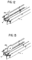
- Fig. 12 and Fig. 13 illustrate the state in which the discharge treatment is performed on the profile 1 in conveyance, respectively with the electrode 20c shaped like a plate as illustrated in Fig. 6 and the electrode 20d shaped like a disc as illustrated in Fig. 7 inserted into the pouring pocket 1a of the profile 1.
- the pouring pocket 1a of the profile 1 which has undergone the discharge treatment as described above is then filled with resin as illustrated in Fig. 14.
- Fig. 14 illustrates one example of the injection of urethane resin.
- Isocyanate and polyol which have been pneumatically conveyed in a volumetric ratio of 1 : 1 from the respective storage tanks (not shown) are fed into a mixing chamber 70 and stirred therein with a mixing rotor 71.
- the resultant mixture is continuously injected via an injection pipe 72 into the pouring pocket 1a of the profile 1 being conveyed on the conveying device (Fig. 10).
- the mixing chamber 70 has the interior thereof cleaned with a solvent.
- the conditions for the injection of the resin may be suitably set depending on such factors as the inner volume of the pouring pocket, it is generally advantageous to fix the conveying speed of the profile in the approximate range of 10 - 30 m/min., the rotating speed of the mixing rotor 71 in the approximate range of 3,000 - 5,000 revolutions per min., and the amount of the urethane resin to be released in the approximate range of 1 - 5 liters/min.
- the position of the injection pipe 72 may be adjusted essentially in the same way as described above in respect to the adjustment of the position of electrode.
- the samples manufactured herein were extruded profiles of aluminum electrophoretically coated with three kinds of acrylic coating material, with the pouring pockets thereof subjected to a corona discharge treatment and then filled with urethane resin.
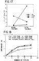
- Fig. 15 through Fig. 17 show changes of the amount of functional groups in the surface of a coating film before and after the discharge treatment; Fig. 15 representing the data obtained of a matt coating material, Fig. 16 the data of a white matt coating material, and Fig. 17 the data of a luster coating material.
- Fig. 15 representing the data obtained of a matt coating material
- Fig. 16 the data of a white matt coating material
- Fig. 17 the data of a luster coating material.
- ESCA electrospray spectroscopy for chemical analysis
- the reagent is fixed on the surface of the coating film when a functional group capable of reacting with the reagent is present in the surface of the coating film, the reagent is easily washed out with a solvent in the absence of such a functional group.
- the test was performed after the urethane resin poured in the profile was left curing for 24 hours. In the test, the tension was applied perpendicularly to the surface of the test piece at a rate of 1 mm/min.
- the maximum tensile strength 311.3 kgf (matt coating material), 363.7 kgf (luster coating material), and 449.2 kgf (white matt coating material) (invariably the average value of three measurements), was obtained.
- heat insulating profiles designed for left vertical frame, right vertical frame, upper frame, and lower frame were manufactured in the same manner as described above, with or without a discharge treatment. They were retained at 60°C for 16 hours, at 23 °C for one hour, then at -20°C for six hours, and thereafter at 23°C for one hour, and subsequently they were returned to the first retention at 60 °C for 16 hours. This cycle of heat treatment was repeated by way of a cooling-heating repeating test. The results are shown in Fig. 18.
Landscapes
- Engineering & Computer Science (AREA)
- Civil Engineering (AREA)
- Structural Engineering (AREA)
- Application Of Or Painting With Fluid Materials (AREA)
- Door And Window Frames Mounted To Openings (AREA)
- Wing Frames And Configurations (AREA)
- Automatic Assembly (AREA)
- Electrical Discharge Machining, Electrochemical Machining, And Combined Machining (AREA)
- Laminated Bodies (AREA)
Applications Claiming Priority (3)
| Application Number | Priority Date | Filing Date | Title |
|---|---|---|---|
| JP16788397A JP3400298B2 (ja) | 1997-06-11 | 1997-06-11 | 樹脂複合アルミニウム形材、断熱アルミニウム形材、それらの製造方法及びそれに用いる装置 |
| JP16788397 | 1997-06-11 | ||
| JP167883/97 | 1997-06-11 |
Publications (3)
| Publication Number | Publication Date |
|---|---|
| EP0884112A2 true EP0884112A2 (de) | 1998-12-16 |
| EP0884112A3 EP0884112A3 (de) | 2000-12-27 |
| EP0884112B1 EP0884112B1 (de) | 2004-09-08 |
Family
ID=15857854
Family Applications (1)
| Application Number | Title | Priority Date | Filing Date |
|---|---|---|---|
| EP98110476A Expired - Lifetime EP0884112B1 (de) | 1997-06-11 | 1998-06-08 | Aluminium-Harz-Verbundprofile und Verfahren zu deren Herstellung |
Country Status (7)
| Country | Link |
|---|---|
| US (2) | US6143372A (de) |
| EP (1) | EP0884112B1 (de) |
| JP (1) | JP3400298B2 (de) |
| KR (1) | KR100284645B1 (de) |
| DE (1) | DE69826064T2 (de) |
| ES (1) | ES2226033T3 (de) |
| ID (1) | ID21300A (de) |
Cited By (3)
| Publication number | Priority date | Publication date | Assignee | Title |
|---|---|---|---|---|
| EP2594382A1 (de) * | 2011-11-21 | 2013-05-22 | Frank Schmidt Verpachtungsunternehmen | Verfahren zum Herstellen eines beschichteten länglichen Profilelements |
| CN105415412A (zh) * | 2015-12-11 | 2016-03-23 | 大连华工创新科技股份有限公司 | 型腔内聚氨酯发泡铝型材u型纸条剪切装置 |
| CN112476009A (zh) * | 2020-10-18 | 2021-03-12 | 党君英 | 一种铝合金型材切割装置 |
Families Citing this family (14)
| Publication number | Priority date | Publication date | Assignee | Title |
|---|---|---|---|---|
| US6895718B2 (en) * | 2003-02-10 | 2005-05-24 | Andrew Mark Moffatt | Construction unit mounting system |
| US7096640B1 (en) * | 2003-05-30 | 2006-08-29 | Traco | Thermal breaking system for construction materials and the like |
| US20070193205A1 (en) * | 2006-01-31 | 2007-08-23 | Nathanael Hill | Method of modifying the surface of a fenestration member |
| US8112941B2 (en) * | 2007-05-16 | 2012-02-14 | Alcoa Commercial Windows Llc | Construction product having a moveable element with multi-functional thermal break |
| US7987633B2 (en) * | 2007-05-16 | 2011-08-02 | Alcoa Commercial Windows Llc | Construction product having a frame with multi-functional thermal break |
| CN101812956B (zh) * | 2009-06-25 | 2012-05-30 | 朱成祥 | 提高浇注式断桥铝型材抗剪性的方法 |
| JP2014128900A (ja) * | 2012-12-28 | 2014-07-10 | Sumika Bayer Urethane Kk | ポリウレタン樹脂一体成形型断熱性金属長尺形材 |
| CA2845638C (en) * | 2013-03-15 | 2016-06-07 | Alcoa Inc. | Method for incorporating thermal barriers into tubular extrusions using retainer clips |
| JP2018071334A (ja) * | 2016-10-27 | 2018-05-10 | 株式会社福地建装 | アルミ製断熱サッシ |
| US11035167B1 (en) * | 2020-03-03 | 2021-06-15 | Quaker Window Products Co. | Thermally enhanced extrudate for windows and doors |
| US20210355744A1 (en) * | 2020-05-15 | 2021-11-18 | Vinyl Window Designs | Sash apparatus and method of making same |
| US11946313B2 (en) | 2020-09-04 | 2024-04-02 | Quaker Window Products Co. | Fenestration unit including slidable glass panels |
| CN115324269B (zh) * | 2022-09-05 | 2023-10-10 | 湖南国宗铝业有限公司 | 一种填充变相材料的铝型材 |
| GB2638261A (en) * | 2024-02-16 | 2025-08-20 | Garner Aluminium Extrusions Ltd | A roof vent |
Citations (1)
| Publication number | Priority date | Publication date | Assignee | Title |
|---|---|---|---|---|
| JPS5419537A (en) | 1977-07-15 | 1979-02-14 | Yamauchi Satsushi Kogyo Kk | Sash |
Family Cites Families (29)
| Publication number | Priority date | Publication date | Assignee | Title |
|---|---|---|---|---|
| NL130914C (de) * | 1964-05-26 | |||
| FR2252421A1 (en) * | 1973-11-27 | 1975-06-20 | Bereday Sigmund | Coating aluminium with resin - by first applying a controlled thickness of active anodising, then applying the resin |
| JPS5134934A (ja) * | 1974-09-20 | 1976-03-25 | Toyo Satsushi Kogyo Kk | Shinshitosohoho |
| DE2633764C2 (de) * | 1976-07-28 | 1978-09-07 | Bayer Ag, 5090 Leverkusen | Verfahren zur Herstellung von Kunststoff -Metall-Verbunden |
| GB2013129B (en) * | 1977-12-20 | 1982-03-31 | Norcros Investments Ltd | Filling of elongate metal members with insulating |
| GB1599284A (en) * | 1978-05-31 | 1981-09-30 | Pryce Jones A & Holt J B | Frame members for double glazing units |
| CH645838A5 (de) * | 1979-04-03 | 1984-10-31 | Hueck Fa E | Vorrichtung zur herstellung von verbundprofilen, insbesondere fuer fensterrahmen, tuerrahmen und fassaden. |
| DE3050779C2 (de) * | 1980-04-25 | 1983-12-15 | Helmar Dr.Dr. 8530 Neustadt Nahr | Verfahren zur Herstellung eines w{rmeisolierenden Profilk¦rpers |
| DE3101709C2 (de) * | 1981-01-21 | 1983-02-10 | Fa. Eduard Hueck, 5880 Lüdenscheid | Verfahren und Vorrichtung zur Herstellung von Verbundprofilen für Fensterrahmen, Türrahmen, Fassadenkonstruktionen o.dgl. |
| JPS5867714A (ja) * | 1981-10-19 | 1983-04-22 | Kurinatsupu Kk | 断熱材 |
| JPS59118421A (ja) * | 1982-12-25 | 1984-07-09 | Yoshida Kogyo Kk <Ykk> | サツシ部材の注入溝に断熱材を充填する方法および装置 |
| JPS59131451A (ja) * | 1983-01-18 | 1984-07-28 | 凸版印刷株式会社 | 金属箔への樹脂のラミネ−ト方法 |
| DE3302161A1 (de) * | 1983-01-22 | 1984-07-26 | Klaus 4803 Steinhagen Kalwar | Vorrichtung zur elektrischen koronabehandlung von profilstraengen aus elektrisch nichtleitendem oder leitendem material und zur weiterbehandlung der oberflaeche |
| FR2544324B1 (fr) * | 1983-04-13 | 1987-07-10 | Toyo Boseki | Procede pour accroitre l'adherence de la surface d'un produit faconne en polyester et produit obtenu par ce procede |
| JPS59225776A (ja) * | 1983-06-08 | 1984-12-18 | Kishimoto Akira | アルミニウム材料の表面処理法 |
| JPS6168988A (ja) * | 1985-05-31 | 1986-04-09 | ワイケイケイ株式会社 | 断熱型材の製造法 |
| JPS62241576A (ja) * | 1986-04-14 | 1987-10-22 | Nikken Sekkei:Kk | 形材の静電塗装方法 |
| DE3702982A1 (de) * | 1987-02-02 | 1988-08-11 | Horn Geb Paul Stephanie | Bei der durchfuehrung von lackierarbeiten auf ein kfz oder einen teil davon aufbringbares bahn- oder haubenfoermiges abdeckmittel |
| US4743672A (en) * | 1987-02-26 | 1988-05-10 | Ashland Oil, Inc. | Sag resistant, two component urethane adhesives |
| US5280084A (en) * | 1988-04-12 | 1994-01-18 | Pp Polymer Ab | Process for improving the hydrophilic properties on polymer surfaces |
| JP2718957B2 (ja) * | 1988-10-05 | 1998-02-25 | ポリプラスチックス株式会社 | 結晶性熱可塑性樹脂成形品の静電塗装方法並びに塗装プラスチックス成形品 |
| DE3827628A1 (de) * | 1988-08-16 | 1990-03-15 | Hoechst Ag | Verfahren und vorrichtung zur oberflaechenvorbehandlung eines formkoerpers aus kunststoff mittels einer elektrischen koronaentladung |
| NL8802982A (nl) * | 1988-12-02 | 1990-07-02 | Thomassen & Drijver | Werkwijze en inrichting voor het activeren van een metaaloppervlak. |
| US5229214A (en) * | 1989-07-31 | 1993-07-20 | Akzo N.V. | Preprimed metal substrates for formed metal applications |
| JPH03189129A (ja) * | 1989-12-19 | 1991-08-19 | Nippon Paint Co Ltd | コロナ放電処理装置 |
| WO1993021415A1 (en) * | 1992-04-16 | 1993-10-28 | H.B. Fuller Licensing & Financing, Inc. | Improved metal casing with thermal break |
| JP2799698B2 (ja) * | 1996-03-22 | 1998-09-21 | 春日電機株式会社 | コロナ放電電極構造 |
| US5780118A (en) * | 1996-07-01 | 1998-07-14 | Xerox Corporation | Method for increasing hydrophilicity of transparencies used as recording media in a thermal ink jet printer |
| US5869188A (en) * | 1997-02-26 | 1999-02-09 | Eastman Kodak Company | Electrostatographic member and system for electrostatographic reproduction and method for preparing same |
-
1997
- 1997-06-11 JP JP16788397A patent/JP3400298B2/ja not_active Expired - Lifetime
-
1998
- 1998-06-05 US US09/090,948 patent/US6143372A/en not_active Expired - Lifetime
- 1998-06-08 DE DE69826064T patent/DE69826064T2/de not_active Expired - Fee Related
- 1998-06-08 ES ES98110476T patent/ES2226033T3/es not_active Expired - Lifetime
- 1998-06-08 EP EP98110476A patent/EP0884112B1/de not_active Expired - Lifetime
- 1998-06-10 ID IDP980848A patent/ID21300A/id unknown
- 1998-06-11 KR KR1019980021687A patent/KR100284645B1/ko not_active Expired - Lifetime
-
2000
- 2000-08-01 US US09/630,707 patent/US6500550B1/en not_active Expired - Lifetime
Patent Citations (1)
| Publication number | Priority date | Publication date | Assignee | Title |
|---|---|---|---|---|
| JPS5419537A (en) | 1977-07-15 | 1979-02-14 | Yamauchi Satsushi Kogyo Kk | Sash |
Cited By (4)
| Publication number | Priority date | Publication date | Assignee | Title |
|---|---|---|---|---|
| EP2594382A1 (de) * | 2011-11-21 | 2013-05-22 | Frank Schmidt Verpachtungsunternehmen | Verfahren zum Herstellen eines beschichteten länglichen Profilelements |
| CN105415412A (zh) * | 2015-12-11 | 2016-03-23 | 大连华工创新科技股份有限公司 | 型腔内聚氨酯发泡铝型材u型纸条剪切装置 |
| CN105415412B (zh) * | 2015-12-11 | 2017-06-06 | 大连华工创新科技股份有限公司 | 型腔内聚氨酯发泡铝型材u型纸条剪切装置 |
| CN112476009A (zh) * | 2020-10-18 | 2021-03-12 | 党君英 | 一种铝合金型材切割装置 |
Also Published As
| Publication number | Publication date |
|---|---|
| JP3400298B2 (ja) | 2003-04-28 |
| ES2226033T3 (es) | 2005-03-16 |
| EP0884112B1 (de) | 2004-09-08 |
| US6500550B1 (en) | 2002-12-31 |
| EP0884112A3 (de) | 2000-12-27 |
| DE69826064D1 (de) | 2004-10-14 |
| KR19990006884A (ko) | 1999-01-25 |
| ID21300A (id) | 1999-05-20 |
| US6143372A (en) | 2000-11-07 |
| DE69826064T2 (de) | 2005-09-22 |
| JPH112072A (ja) | 1999-01-06 |
| KR100284645B1 (ko) | 2001-08-07 |
Similar Documents
| Publication | Publication Date | Title |
|---|---|---|
| EP0981667B1 (de) | Ausgefälltes aragonit kalciumkarbonatpigment zur beschichtung von tiefdruckpapieren | |
| EP0884112B1 (de) | Aluminium-Harz-Verbundprofile und Verfahren zu deren Herstellung | |
| US5105591A (en) | Spacer frame for an insulating glass panel and method of making the same | |
| US4628582A (en) | Method of making spacer frame for an insulating glass panel | |
| US4530195A (en) | Spacer frame for an insulating glass panel and method of making the same | |
| DE3269522D1 (en) | Profile strip, in particular for the production of window or door frames | |
| JPS6470220A (en) | Automobile window glass for direct bonding | |
| DE69728329T2 (de) | Herstellungsverfahren für Mehrfachverglasungen mit Plastikzwischenfolien | |
| DE3802527A1 (de) | Druckempfindlicher fuehler | |
| AU589608B2 (en) | Encapsulated multiple glazed unit | |
| JP2669607B2 (ja) | 碍子の製造方法、および同方法を実施するための装置 | |
| WO1997049887A1 (de) | Isolierglaseinheit | |
| TR199500939A2 (tr) | Kapi ve pencere cerceveleri icin kompozit metal-ahsap profil seti. | |
| JPS61188224A (ja) | 自動車や建築物の窓や戸の開口部の密着囲い用の枠レール | |
| AU7759598A (en) | Method for producing bent hollow profile strips | |
| EP0805254A3 (de) | Verfahren zum Herstellen von Isolierglasscheiben mit thermoplastischem Abstandhalter | |
| EP0154121B1 (de) | Verfahren zum Herstellen von Dichtungsstreifen und ähnlichen Profilsträngen aus Kautschuk und kautschukartigen Elastomeren | |
| EP0918129A3 (de) | Fenster, Türe oder dergl. | |
| DE19644346A1 (de) | Wärmedämmender Abstandhalter für Isolierverglasungen | |
| SE510064C2 (sv) | Förfarande och anordning för framställning av elektrisk isolator med skruv- eller spiralformad beläggning | |
| DE3802077A1 (de) | Glaswand oder fassade | |
| AR244140A1 (es) | Mejoras en un perfil de guia y estanqueidad para un vidrio movil, especialmente en una puerta de automovil. | |
| CA1293888C (en) | Encapsulated glazing structure | |
| WO2001036192A1 (en) | Steel-plastic laminating profile and the manufacturing process thereof | |
| IT8922432A0 (it) | Metodo ed apparecchiatura per verificare e regolare il posizionamento dei trefoli di rinforzo metallici in fogli di gomma in particolare per la costruzione di pneumatici |
Legal Events
| Date | Code | Title | Description |
|---|---|---|---|
| PUAI | Public reference made under article 153(3) epc to a published international application that has entered the european phase |
Free format text: ORIGINAL CODE: 0009012 |
|
| AK | Designated contracting states |
Kind code of ref document: A2 Designated state(s): DE ES SE |
|
| AX | Request for extension of the european patent |
Free format text: AL;LT;LV;MK;RO;SI |
|
| EUG | Se: european patent has lapsed | ||
| PUAL | Search report despatched |
Free format text: ORIGINAL CODE: 0009013 |
|
| AK | Designated contracting states |
Kind code of ref document: A3 Designated state(s): AT BE CH CY DE DK ES FI FR GB GR IE IT LI LU MC NL PT SE |
|
| AX | Request for extension of the european patent |
Free format text: AL;LT;LV;MK;RO;SI |
|
| 17P | Request for examination filed |
Effective date: 20010531 |
|
| AKX | Designation fees paid |
Free format text: DE ES SE |
|
| 17Q | First examination report despatched |
Effective date: 20020730 |
|
| RTI1 | Title (correction) |
Free format text: RESIN-COMPOSITE ALUMINUM PROFILES AND METHOD FOR PRODUCTION THEREOF |
|
| GRAJ | Information related to disapproval of communication of intention to grant by the applicant or resumption of examination proceedings by the epo deleted |
Free format text: ORIGINAL CODE: EPIDOSDIGR1 |
|
| GRAP | Despatch of communication of intention to grant a patent |
Free format text: ORIGINAL CODE: EPIDOSNIGR1 |
|
| GRAP | Despatch of communication of intention to grant a patent |
Free format text: ORIGINAL CODE: EPIDOSNIGR1 |
|
| RTI1 | Title (correction) |
Free format text: RESIN-COMPOSITE ALUMINUM PROFILES AND METHOD FOR PRODUCTION THEREOF |
|
| RAP1 | Party data changed (applicant data changed or rights of an application transferred) |
Owner name: YKK AP INC. |
|
| GRAS | Grant fee paid |
Free format text: ORIGINAL CODE: EPIDOSNIGR3 |
|
| GRAA | (expected) grant |
Free format text: ORIGINAL CODE: 0009210 |
|
| AK | Designated contracting states |
Kind code of ref document: B1 Designated state(s): DE ES SE |
|
| REG | Reference to a national code |
Ref country code: SE Ref legal event code: TRGR |
|
| REF | Corresponds to: |
Ref document number: 69826064 Country of ref document: DE Date of ref document: 20041014 Kind code of ref document: P |
|
| REG | Reference to a national code |
Ref country code: ES Ref legal event code: FG2A Ref document number: 2226033 Country of ref document: ES Kind code of ref document: T3 |
|
| PLBE | No opposition filed within time limit |
Free format text: ORIGINAL CODE: 0009261 |
|
| STAA | Information on the status of an ep patent application or granted ep patent |
Free format text: STATUS: NO OPPOSITION FILED WITHIN TIME LIMIT |
|
| 26N | No opposition filed |
Effective date: 20050609 |
|
| PGFP | Annual fee paid to national office [announced via postgrant information from national office to epo] |
Ref country code: SE Payment date: 20060607 Year of fee payment: 9 |
|
| PGFP | Annual fee paid to national office [announced via postgrant information from national office to epo] |
Ref country code: ES Payment date: 20060626 Year of fee payment: 9 |
|
| EUG | Se: european patent has lapsed | ||
| PG25 | Lapsed in a contracting state [announced via postgrant information from national office to epo] |
Ref country code: SE Free format text: LAPSE BECAUSE OF NON-PAYMENT OF DUE FEES Effective date: 20070609 |
|
| REG | Reference to a national code |
Ref country code: ES Ref legal event code: FD2A Effective date: 20070609 |
|
| PG25 | Lapsed in a contracting state [announced via postgrant information from national office to epo] |
Ref country code: ES Free format text: LAPSE BECAUSE OF NON-PAYMENT OF DUE FEES Effective date: 20070609 |
|
| PGFP | Annual fee paid to national office [announced via postgrant information from national office to epo] |
Ref country code: DE Payment date: 20080612 Year of fee payment: 11 |
|
| PG25 | Lapsed in a contracting state [announced via postgrant information from national office to epo] |
Ref country code: DE Free format text: LAPSE BECAUSE OF NON-PAYMENT OF DUE FEES Effective date: 20100101 |