EP0884121A2 - Procédé de fabrication d'une boíte à fluide tubulaire - Google Patents
Procédé de fabrication d'une boíte à fluide tubulaire Download PDFInfo
- Publication number
- EP0884121A2 EP0884121A2 EP98110688A EP98110688A EP0884121A2 EP 0884121 A2 EP0884121 A2 EP 0884121A2 EP 98110688 A EP98110688 A EP 98110688A EP 98110688 A EP98110688 A EP 98110688A EP 0884121 A2 EP0884121 A2 EP 0884121A2
- Authority
- EP
- European Patent Office
- Prior art keywords
- semidivided cylindrical
- connecting portion
- cylindrical portions
- semidivided
- header pipe
- Prior art date
- Legal status (The legal status is an assumption and is not a legal conclusion. Google has not performed a legal analysis and makes no representation as to the accuracy of the status listed.)
- Withdrawn
Links
Images


Classifications
-
- F—MECHANICAL ENGINEERING; LIGHTING; HEATING; WEAPONS; BLASTING
- F28—HEAT EXCHANGE IN GENERAL
- F28F—DETAILS OF HEAT-EXCHANGE AND HEAT-TRANSFER APPARATUS, OF GENERAL APPLICATION
- F28F9/00—Casings; Header boxes; Auxiliary supports for elements; Auxiliary members within casings
- F28F9/02—Header boxes; End plates
- F28F9/0202—Header boxes having their inner space divided by partitions
- F28F9/0204—Header boxes having their inner space divided by partitions for elongated header box, e.g. with transversal and longitudinal partitions
- F28F9/0209—Header boxes having their inner space divided by partitions for elongated header box, e.g. with transversal and longitudinal partitions having only transversal partitions
-
- B—PERFORMING OPERATIONS; TRANSPORTING
- B21—MECHANICAL METAL-WORKING WITHOUT ESSENTIALLY REMOVING MATERIAL; PUNCHING METAL
- B21D—WORKING OR PROCESSING OF SHEET METAL OR METAL TUBES, RODS OR PROFILES WITHOUT ESSENTIALLY REMOVING MATERIAL; PUNCHING METAL
- B21D53/00—Making other particular articles
- B21D53/02—Making other particular articles heat exchangers or parts thereof, e.g. radiators, condensers fins, headers
- B21D53/04—Making other particular articles heat exchangers or parts thereof, e.g. radiators, condensers fins, headers of sheet metal
-
- F—MECHANICAL ENGINEERING; LIGHTING; HEATING; WEAPONS; BLASTING
- F28—HEAT EXCHANGE IN GENERAL
- F28F—DETAILS OF HEAT-EXCHANGE AND HEAT-TRANSFER APPARATUS, OF GENERAL APPLICATION
- F28F9/00—Casings; Header boxes; Auxiliary supports for elements; Auxiliary members within casings
- F28F9/02—Header boxes; End plates
- F28F9/0243—Header boxes having a circular cross-section
-
- Y—GENERAL TAGGING OF NEW TECHNOLOGICAL DEVELOPMENTS; GENERAL TAGGING OF CROSS-SECTIONAL TECHNOLOGIES SPANNING OVER SEVERAL SECTIONS OF THE IPC; TECHNICAL SUBJECTS COVERED BY FORMER USPC CROSS-REFERENCE ART COLLECTIONS [XRACs] AND DIGESTS
- Y10—TECHNICAL SUBJECTS COVERED BY FORMER USPC
- Y10T—TECHNICAL SUBJECTS COVERED BY FORMER US CLASSIFICATION
- Y10T29/00—Metal working
- Y10T29/49—Method of mechanical manufacture
- Y10T29/4935—Heat exchanger or boiler making
- Y10T29/49389—Header or manifold making
-
- Y—GENERAL TAGGING OF NEW TECHNOLOGICAL DEVELOPMENTS; GENERAL TAGGING OF CROSS-SECTIONAL TECHNOLOGIES SPANNING OVER SEVERAL SECTIONS OF THE IPC; TECHNICAL SUBJECTS COVERED BY FORMER USPC CROSS-REFERENCE ART COLLECTIONS [XRACs] AND DIGESTS
- Y10—TECHNICAL SUBJECTS COVERED BY FORMER USPC
- Y10T—TECHNICAL SUBJECTS COVERED BY FORMER US CLASSIFICATION
- Y10T29/00—Metal working
- Y10T29/49—Method of mechanical manufacture
- Y10T29/4935—Heat exchanger or boiler making
- Y10T29/49391—Tube making or reforming
-
- Y—GENERAL TAGGING OF NEW TECHNOLOGICAL DEVELOPMENTS; GENERAL TAGGING OF CROSS-SECTIONAL TECHNOLOGIES SPANNING OVER SEVERAL SECTIONS OF THE IPC; TECHNICAL SUBJECTS COVERED BY FORMER USPC CROSS-REFERENCE ART COLLECTIONS [XRACs] AND DIGESTS
- Y10—TECHNICAL SUBJECTS COVERED BY FORMER USPC
- Y10T—TECHNICAL SUBJECTS COVERED BY FORMER US CLASSIFICATION
- Y10T29/00—Metal working
- Y10T29/49—Method of mechanical manufacture
- Y10T29/4935—Heat exchanger or boiler making
- Y10T29/49393—Heat exchanger or boiler making with metallurgical bonding
Definitions
- the present invention relates to a method for manufacturing a header pipe which con be used as a tank in a heat exchanger.
- a partition is provided in a header to thereby change the passage of fluid.
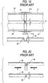
- a header with a partition of this type for use in a heat exchanger is manufactured in the following manner as shown in Fig. 15.
- a pipe member which is formed of aluminum alloy and the outer surface of which is cladded with brazing material, is cut into a given dimension, thereby producing a pipe 11 for a header.
- an aluminum alloy divide 21 with the two surfaces thereof cladded with brazing material is inserted into the divide slit 15, and also two patches 23 formed of aluminum alloy are respectively pressure inserted into the two ends of the pipe 11 so as to manufacture a header pipe.
- the conventional header raises a fear that poor brazing can occur between the divide 21 and the pipe 11.
- a pipe with a partition structured such that it includes a partition portion 33 comprising a pair of semidivided partition portions 32.
- this pipe with a partition is manufactured in the following manner:
- a plate member formed of aluminum is molded so that there are formed a pair of semidivided cylindrical portions 35.
- the pair of semidivided cylindrical portions 35 are arranged in parallel to each other with an arc-shaped connecting portion 37 between them.
- Each of the pair of semidivided cylindrical portions 35 has a diameter smaller by 2 mm or so than the radius of a pipe portion 31 to be formed and, on the outside of each semidivided cylindrical portion 35, there is formed an edge portion 41.
- the above-mentioned molding step can be achieved by holding the flat plate between given metal molds and then molding the same by pressing.
- This cutting step can be attained by trimming and piercing the flat plate using a piece of press work machinery.
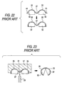
- the partition forming portions 39 are respectively compressed from the two sides thereof in a direction of arrows B in Fig. 20 to thereby form a semidivided partition portion 32.
- This compressing step is carried out in such a manner as shown in Fig. 21: that is, the outside portions of the two semidivided cylindrical portions 35 are held by a work holder 51 to be energized by springs 49, and, on the other hand, pressing members 53 are respectively disposed on the two sides of the partition forming portions 39 situated inside the two semidivided cylindrical portions 35; and, after then, if the partition forming portions 39 are compression molded by the compressing members 53, then the semidivided partition portion 32 can be formed.
- a dimension correcting block 55 between the compressing members 53, so that the inward projecting length H of the semidivided partition portion 32 can be corrected by the dimension correcting block 55.
- each edge portion 41 is formed in an arc shape which continues with its associated semidivided cylindrical portion 35.
- This edge portion molding stop can be achieved by holding the pair of semidivided cylindrical portions 35 between given metal molds and then molding the same by pressing.
- the connecting portion 37 is projected from the inside thereof to thereby dispose the pair of semidivided cylindrical portions 35 in such a manner that they are opposed to each other.
- This mutually opposing step is carried out by storing the outside portions of the semidivided cylindrical portions 35 into a metal mold 57 and then pressing the connecting portion 37 against the arc-shaped portion 61 of the metal mold 57 using a punch 59.
- This butting step is executed by storing the outside portions of the semidivided cylindrical portions 35 into a pair of metal molds (not shown) and then moving the metal molds. As a result of this, the semidivided cylindrical portions 35 are molded into a pipe shape.
- a connecting step is carried out: that is, not only the pair of semidivided cylindrical portions 35 but also the pair of semidivided partition portions 32 are connected to each other, so that the pipe with a partition shown in Figs. 16 and 17 can be manufactured.
- This connecting step can be achieved by performing, for example, a brazing operation using non-corrosive flux.
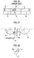
- Fig. 25 shows a header with a partition for a heat exchanger which is manufactured according to the above-mentioned method for manufacturing a pipe with a partition.
- the present header with a partition for a heat exchanger includes a partition portion 33 formed in the center portion of a cylindrically-shaped pipe portion 31A thereof.
- the tube insertion holes 63 in one of the semidivided cylindrical portions 35, the tube insertion holes 63 in such a manner that they are spaced from each other at given intervals; and, at the same time, there are also formed a fluid flow-in port 67 into which a thermal medium is allowed to flow, and a fluid flow-out port 69 from which the thermal medium is allowed to flow.
- This step can be achieved by slit/pierce molding using a piece of press work machinery.
- the integral formation of the partition portion can reduce the number of parts, which makes it possible to reduce the coat of the header.
- the tube insertion hole 63 can be worked in a semicircle state, the tube insertion hole 63 after molded con provide a sufficient strength, the working time thereof can be shortened, end thus the cost of the header con be reduced.
- the radius R2 of the connecting portion 37 and the radius R1 of the semidivided cylindrical portion 35 are set substantially equal to each other
- the peripheral length AB of the semidivided cylindrical portion 35 which extends from a connecting point A between the semidivided cylindrical portion 35 and connecting portion 37 to a virtual intersecting point B where a center connecting line L connecting the respective centers of the pair of semidivided cylindrical portions 35 with each other intersects the semidivided cylindrical portion 35, is set substantially the same as the peripheral length AC extending from the connecting point A to the center point C of the connecting portion 37; and also, the tube insertion holes 63 are respectively formed in such a manner that they extend up to the connecting portion 37.
- the end portion 63a of the tube insertion hole 63 is tapered to make the insertion of the tube into the tube insertion hole 63 easy in advance as shown in Fig. 28.
- the mutually opposing step shown in Fig. 23 and the butting step shown in Fig. 24 are carried out, then, there is raised a problem that the end portion 63a of the tube insertion hole 63 is deformed and the tapered portion is deformed so that the insertion of the tube into the tube insertion hole 63 becomes difficult.
- the present invention aims at eliminating the above-mentioned drawbacks found in the conventional header pipe manufacturing methods. Accordingly, it is an object of the invention to provide a method for manufacturing a header pipe which is surely able to prevent the end portion of the tube insertion hole from being deformed.
- a method for manufacturing a header pipe comprising the steps of: molding a flat plate so that a pair of semidivided cylindrical portions are arranged in parallel to each other with a connecting portion therebetween; forming a tube insertion hole in one of the pair of semidivided cylindrical portions so that the tube insertion hole is not allowed to extend up to the connecting portion; projecting the connecting portion to thereby dispose the pair of semidivided cylindrical portions so as to be opposed to each other; and butting the mutually opposed semidivided cylindrical portions against each other, thereby manufacturing a cylindrically-shaped header pipe.
- the connecting portion is arc-shaped in a cross section, and a radius of the connecting portion in the cross section is set smaller than a radius of the semidivided cylindrical portions in a cross section.
- a virtual peripheral length of the semidivided cylindrical portion in a cross section which extends from a connecting point of the semidivided cylindrical portion and the connecting portion to a virtual intersecting point where a center connecting line connecting respective centers of the pair of semidivided cylindrical portions with each other intersect each of virtually extended peripheries of the semidivided cylindrical portions, is set substantially same as a peripheral length of the connecting portion in a cross section extending from the connecting point to a center point of the connecting portion.
- the tube insertion holes are formed only in one of the pair of semidivided cylindrical portions in such a manner that the tube insertion holes are not allowed to extend up to the connecting portion, and, after then, the mutually opposing step and butting step are carried out to thereby manufacture the cylindrically-shaped header pipe.
- the radius of the connecting portion is set smaller than the radius of the semidivided cylindrical portion.
- the peripheral length of the semidivided cylindrical portion which extends from the connecting point between the semidivided cylindrical portion and the connecting portion to a virtual intersecting point where the center connecting line connecting the respective centers of the pair of semidivided cylindrical portions with each other intersects each of the semidivided cylindrical portions, is set substantially the same as the peripheral length of the connecting portion extending from the above-mentioned connecting point to the center point of the connecting portion.
- Fig. 1 is an explanatory view of an embodiment of a method for manufacturing a header pipe according to the invention, showing a state thereof after a molding step thereof is executed.
- this state as a result of molding of an aluminum flat plate, there are formed a pair of semidivided cylindrical portions 71 which are arranged in parallel to each other with an arc-shaped connecting portion 73 between them.
- the radius R2 of the connecting portion 73 is set smaller then the radius R1 of the semidivided cylindrical portion 71.
- the virtual peripheral length PO of the semidivided cylindrical portion 71 which extends from a connecting point P between the semidivided cylindrical portion 71 and the connecting portion 73 to a virtual intersecting point O where the center connecting line L connecting the respective centers of the pair of semidivided cylindrical portions 71 with each other intersects each of the virtually extended periphery of the semidivided cylindrical portions 71, is set substantially the same as the peripheral length PQ of the connecting portion 73 extending from the above-mentioned connecting point P to the center point Q of the connecting portion 73.
- the length dimension L1 of the tube insertion hole 75 is set such that one end of the tube insertion hole 75 is not allowed to extend up to the connecting portion 73.
- This step is carried out by slit/pierce molding the aluminum flat plate using a piece of press work machinery.
- the connecting portion 73 is projected from the inside thereof so that the pair of semidivided cylindrical portions 71 are disposed opposed to each other at an angular interval of, for example, 30 degree.
- This mutually opposing step is executed by storing the outside portions of the semidivided cylindrical portions 71 into a metal mold and then pressing the connecting portion 73 against the arc-shaped portion of the metal mold using a punch.
- the tuba insertion hole 75 is formed only in one of the semidivided cylindrical portions 71 in such a manner that it is not allowed to extend up to the connecting portion 73, when, after then, the mutually opposing step and butting step are carried out to thereby manufacture the cylindrically-shaped header pipe, it is possible to surely prevent the end portion of the tube insertion hole 75 from being deformed.
- the radius R2 of the connecting portion 73 is set smaller than the radius R1 of the semidivided cylindrical portion 71, it is possible to increase the outer peripheral length of the semidivided cylindrical portion 71, so that the length L1 of the tube insertion hole 75 can be set as the length that is required of a header pipe having a given outside diameter dimension.
- the radius R2 of the connecting portion 73 is set smaller than the radius R1 of the semidivided cylindrical portion 71, it is possible to increase the outer peripheral length of the semidivided cylindrical portion 71, so that the length L1 of the tube insertion hole 75 can be set easily as the length that is required of a header pipe having a given outside diameter dimension.
- the virtual peripheral length PO of the semidivided cylindrical portion 71 which extends from a connecting point P between the semidivided cylindrical portion 71 and the connecting portion 73 to a virtual intersecting point O where the center connecting line L connecting the respective centers of the pair of semidivided cylindrical portions 71 with each other intersects each of the virtually extended periphery of the semidivided cylindrical portions 71, is set substantially the same as the peripheral length PQ of the connecting portion 73 extending from the above-mentioned connecting point P to the center point Q of the connecting portion 73, after then, by carrying out the mutually opposing step and butting step, the cylindrically-shaped header pipe can be produced positively.
- a header pipe with a partition is manufactured from an aluminum flat plate.
- the present header pipe is manufactured in the following manner:
- an aluminum plate member including brazing layers on the two surfaces thereof is molded to thereby form a pair of semidivided cylindrical portions 101.
- the pair of semidivided cylindrical portions 101 are arranged in parallel to each other with an arc-shaped connecting portion 103 between them.
- Each of the semidivided cylindrical portions 101 includes an edge portion 107 on the outside thereof.
- the radius of the connecting portion 103 is set smaller than the radius of the semidivided cylindrical portion 101.
- the virtual peripheral length of the semidivided cylindrical portion 101 which extends from a connecting point between the semidivided cylindrical portion 101 and the connecting portion 103 to a virtual intersecting point where a center connecting line connecting the respective centers of the pair of semidivided cylindrical portions 101 with each other intersects each of virtually extended periphery of the semidivided cylindrical portions 101, is set substantially the same as the peripheral length of the connecting portion 103 extending from the above-mentioned connecting point to the center point of the connecting portion 103.
- the above-mentioned molding step is carried out by holding the flat plate between given metal molds and then molding the same by pressing.
- the base portion of the partition forming portion 105 is molded into on arc shape having a given radius.
- This cutting step is executed by trimming and piercing the flat plate using, a piece of press work machinery.
- the partition forming portions 105 are compressed from the two sides thereof to thereby form a semidivided partition portion 109.
- edge portions 107 of the pair of semidivided cylindrical portions 101 situated on the two sides thereof are molded in such a manner that, as shown in the side view of Fig. 7, each edge portion 107 is formed into an arc shape which continues with its associated semidivided cylindrical portion 10.
- a stepped portion 111 there is formed a stepped portion 111 and, at the same time, securing recessed portions 113 in which the caulking pawl portions are caulked and fixed, as well as pressing recessed portions 115 are respectively worked by embossing.
- This edge portion molding step is carried out by holding the pair of semidivided cylindrical portions 101 between given metal molds and then molding the same by pressing.
- the unnecessary portions of the edge portions 107 except for the portions that are used as caulking pawl portions 117 are trimmed and worked, thereby forming the caulking pawl portions 117.
- a first tube insertion hole forming step shown in Fig. 11 in the central portion of one of the pair of semidivided cylindrical portions 101, there are formed a plurality of tube insertion holes 119 which are spaced at given intervals from each other and, on the two sides of the present semidivided cylindrical portion 101, there are formed side plate insertion holes 121.
- the length of the tube insertion hole 119 is set as the length that is required of a header pipe having a given outside diameter dimension to be manufactured.
- This tube insertion hole forming step can be achieved by slit/pierce molding the flat plate using a piece of press work machinery.
- This second tube insertion hole forming step can be achieved by slit/pierce molding the flat plate using a piece of press work machinery.
- the connecting portion 103 is projected from the inside thereof to thereby dispose the pair of semidivided cylindrical portions 101 in such a manner that they are opposed to each other.
- the caulking pawl portions 117 are respectively staked and fixed to the securing recessed portions 113 according to a caulking step (not shown) and, in such staked and fixed state, not only the pair of semidivided cylindrical portions 101 but also the pair of semidivided partition portions 109 are connected to each other.
- the connecting step is executed by performing a brasing operation using non-corrosive flux.
- the length of the tube insertion hole 119 can be set as the length that is required of a header pipe having a given outside diameter dimension.
- the tube insertion hole are formed only in one of the pair of semidivided cylindrical portions in such a manner that the tube insertion holes are not allowed to extend up to the connecting portion. Duo to this, after then, when the mutually opposing step and butting step are carried out to thereby manufacture the cylindrically-shaped header pipe, it is possible to surely prevent the end portions of the tube insertion holes from being deformed.
- the radius of the connecting portion is set smaller than the radius of the semidivided cylindrical portion, it is possible to increase the outer peripheral length of the semidivided cylindrical portion, so that the length of the tube insertion hole can be net easily as the length that is required of a header pipe having a given outside diameter dimension.
- the virtual peripheral length of the semidivided cylindrical portion which extends from the connecting point between the semidivided cylindrical portion and the connecting portion to a virtual intersecting point where the center connecting line connecting the respective centers of the pair of semidivided cylindrical portions with each other intersects each of virtually extended periphery of the semidivided cylindrical portions, is set substantially the same as the peripheral length of the connecting portion extending from the above-mentioned connecting point to the center point of the connecting portion.
Landscapes
- Engineering & Computer Science (AREA)
- Mechanical Engineering (AREA)
- Physics & Mathematics (AREA)
- Thermal Sciences (AREA)
- General Engineering & Computer Science (AREA)
- Branch Pipes, Bends, And The Like (AREA)
- Lining Or Joining Of Plastics Or The Like (AREA)
- Rigid Pipes And Flexible Pipes (AREA)
Applications Claiming Priority (6)
| Application Number | Priority Date | Filing Date | Title |
|---|---|---|---|
| JP15339297 | 1997-06-11 | ||
| JP15339297 | 1997-06-11 | ||
| JP153392/97 | 1997-06-11 | ||
| JP10050536A JPH1157912A (ja) | 1997-06-11 | 1998-03-03 | ヘッダーパイプの製造方法 |
| JP50536/98 | 1998-03-03 | ||
| JP5053698 | 1998-03-03 |
Publications (2)
| Publication Number | Publication Date |
|---|---|
| EP0884121A2 true EP0884121A2 (fr) | 1998-12-16 |
| EP0884121A3 EP0884121A3 (fr) | 2002-01-16 |
Family
ID=26391016
Family Applications (1)
| Application Number | Title | Priority Date | Filing Date |
|---|---|---|---|
| EP98110688A Withdrawn EP0884121A3 (fr) | 1997-06-11 | 1998-06-10 | Procédé de fabrication d'une boíte à fluide tubulaire |
Country Status (3)
| Country | Link |
|---|---|
| US (1) | US6049981A (fr) |
| EP (1) | EP0884121A3 (fr) |
| JP (1) | JPH1157912A (fr) |
Cited By (1)
| Publication number | Priority date | Publication date | Assignee | Title |
|---|---|---|---|---|
| ES2253999A1 (es) * | 2003-08-07 | 2006-06-01 | Framatome Anp. | Intercambiador de calor y, en particular, generador de vapor con fondo convexo. |
Families Citing this family (3)
| Publication number | Priority date | Publication date | Assignee | Title |
|---|---|---|---|---|
| EP0884120B1 (fr) * | 1997-06-11 | 2004-09-01 | Calsonic Kansei Corporation | Procédé et dispositif de fabrication d'une boíte à eau tubulaire |
| JP3670135B2 (ja) * | 1998-05-06 | 2005-07-13 | 俊臣 林 | 枝管を一体に備えた管状体の製造方法 |
| US7296461B2 (en) | 2002-12-03 | 2007-11-20 | Ppg Industries Ohio, Inc. | Temperature compensated windshield moisture detector |
Citations (2)
| Publication number | Priority date | Publication date | Assignee | Title |
|---|---|---|---|---|
| JPH0463982U (fr) | 1990-10-08 | 1992-06-01 | ||
| JPH07314035A (ja) | 1994-03-29 | 1995-12-05 | Calsonic Corp | 仕切り付パイプの製造方法 |
Family Cites Families (7)
| Publication number | Priority date | Publication date | Assignee | Title |
|---|---|---|---|---|
| JPH0284250A (ja) * | 1988-07-14 | 1990-03-26 | Showa Alum Corp | ろう付用パイプの製造方法 |
| US5243842A (en) * | 1988-07-14 | 1993-09-14 | Showa Aluminum Kabushiki Kaisha | Method of making a brazeable metal pipe having tube-insertion apertures formed with guide lugs |
| JPH02165832A (ja) * | 1988-12-15 | 1990-06-26 | Calsonic Corp | 熱交換器用タンクの製造方法 |
| US5119552A (en) * | 1990-02-16 | 1992-06-09 | Sanden Corporation | Method for manufacturing header pipe of heat exchanger |
| US5329995A (en) * | 1992-08-28 | 1994-07-19 | Valeo Engine Cooling Incorporated | Heat exchanger assembly I |
| JP3616679B2 (ja) * | 1995-09-07 | 2005-02-02 | カルソニックカンセイ株式会社 | 端部閉塞パイプおよび熱交換器用ヘッダー |
| US5781808A (en) * | 1996-03-27 | 1998-07-14 | Fuji Photo Optical Co., Ltd. | Zoom-lens drive control apparatus |
-
1998
- 1998-03-03 JP JP10050536A patent/JPH1157912A/ja active Pending
- 1998-06-10 EP EP98110688A patent/EP0884121A3/fr not_active Withdrawn
- 1998-06-11 US US09/095,420 patent/US6049981A/en not_active Expired - Fee Related
Patent Citations (2)
| Publication number | Priority date | Publication date | Assignee | Title |
|---|---|---|---|---|
| JPH0463982U (fr) | 1990-10-08 | 1992-06-01 | ||
| JPH07314035A (ja) | 1994-03-29 | 1995-12-05 | Calsonic Corp | 仕切り付パイプの製造方法 |
Cited By (2)
| Publication number | Priority date | Publication date | Assignee | Title |
|---|---|---|---|---|
| ES2253999A1 (es) * | 2003-08-07 | 2006-06-01 | Framatome Anp. | Intercambiador de calor y, en particular, generador de vapor con fondo convexo. |
| ES2253999B2 (es) * | 2003-08-07 | 2007-08-16 | Framatome Anp. | Intercambiador de calor y, en particular, generador de vapor con fondo convexo. |
Also Published As
| Publication number | Publication date |
|---|---|
| EP0884121A3 (fr) | 2002-01-16 |
| JPH1157912A (ja) | 1999-03-02 |
| US6049981A (en) | 2000-04-18 |
Similar Documents
| Publication | Publication Date | Title |
|---|---|---|
| US5119552A (en) | Method for manufacturing header pipe of heat exchanger | |
| JPH06159986A (ja) | 熱交換器用チューブおよびその製造方法 | |
| JPH05172488A (ja) | 熱交換器用ヘッダ−パイプの仕切板組付構造及び組付方法 | |
| JP3449897B2 (ja) | 熱交換器及びその製造方法 | |
| US6053243A (en) | Header pipe for heat exchanger and manufacturing apparatus and manufacturing method thereof | |
| EP0884122B1 (fr) | Procédé de fabrication d'un tuyau avec une cloison | |
| CZ285478B6 (cs) | Způsob výroby kovové trubky, pájitelné na tvrdo, opatřené otvory pro vkládání dalších trubek | |
| EP0884121A2 (fr) | Procédé de fabrication d'une boíte à fluide tubulaire | |
| EP0884120B1 (fr) | Procédé et dispositif de fabrication d'une boíte à eau tubulaire | |
| JP2804156B2 (ja) | 熱交換器用伝熱管の製造方法 | |
| US5743122A (en) | Apparatus for making a manifold for an automotive heat exchanger | |
| EP0761337B1 (fr) | Tube avec une cloison transversale, boíte à fluide tubulaire pour échangeur de chaleur et son procédé de fabrication | |
| EP0736346B1 (fr) | Procédé de fabrication d'un évaporateur pour des véhicules automobiles | |
| JP2008516177A (ja) | 熱交換器用扁平管 | |
| JP3913887B2 (ja) | 仕切り付パイプの製造方法 | |
| JPH03238130A (ja) | 熱交換器用ヘッダーパイプの製造方法 | |
| JP2002086232A (ja) | 熱交換器用ヘッダーパイプの製造方法 | |
| EP1577628A1 (fr) | Reservoir pour echangeur de chaleur | |
| JPH08145586A (ja) | 熱交換器用偏平チューブ | |
| JP3831480B2 (ja) | ヘッダーパイプの製造方法 | |
| US5901443A (en) | Method of making a manifold for an automotive heat exchanger | |
| JP3642644B2 (ja) | 仕切壁と流量調整壁とを有する熱交換器用ヘッダの製造方法 | |
| KR100305507B1 (ko) | 에어콘의 적층형 열교환기용 매니폴드 및 그 제조방법 | |
| JPH10213389A (ja) | 熱交換器 | |
| JP2602060B2 (ja) | 分岐管継手の製造方法 |
Legal Events
| Date | Code | Title | Description |
|---|---|---|---|
| PUAI | Public reference made under article 153(3) epc to a published international application that has entered the european phase |
Free format text: ORIGINAL CODE: 0009012 |
|
| AK | Designated contracting states |
Kind code of ref document: A2 Designated state(s): AT BE CH CY DE DK ES FI FR GB GR IE IT LI LU MC NL PT SE Kind code of ref document: A2 Designated state(s): DE FR GB |
|
| AX | Request for extension of the european patent |
Free format text: AL;LT;LV;MK;RO;SI |
|
| RAP1 | Party data changed (applicant data changed or rights of an application transferred) |
Owner name: CALSONIC KANSEI CORPORATION |
|
| PUAL | Search report despatched |
Free format text: ORIGINAL CODE: 0009013 |
|
| AK | Designated contracting states |
Kind code of ref document: A3 Designated state(s): AT BE CH CY DE DK ES FI FR GB GR IE IT LI LU MC NL PT SE |
|
| AX | Request for extension of the european patent |
Free format text: AL;LT;LV;MK;RO;SI |
|
| RIC1 | Information provided on ipc code assigned before grant |
Free format text: 7B 21D 53/02 A, 7F 28F 9/02 B, 7B 21D 53/04 B |
|
| 17P | Request for examination filed |
Effective date: 20020222 |
|
| AKX | Designation fees paid |
Free format text: DE FR GB |
|
| 17Q | First examination report despatched |
Effective date: 20030711 |
|
| STAA | Information on the status of an ep patent application or granted ep patent |
Free format text: STATUS: THE APPLICATION IS DEEMED TO BE WITHDRAWN |
|
| 18D | Application deemed to be withdrawn |
Effective date: 20031122 |