EP0884133A1 - Procede et appareil de production d'un oscillateur a quartz - Google Patents
Procede et appareil de production d'un oscillateur a quartz Download PDFInfo
- Publication number
- EP0884133A1 EP0884133A1 EP97935811A EP97935811A EP0884133A1 EP 0884133 A1 EP0884133 A1 EP 0884133A1 EP 97935811 A EP97935811 A EP 97935811A EP 97935811 A EP97935811 A EP 97935811A EP 0884133 A1 EP0884133 A1 EP 0884133A1
- Authority
- EP
- European Patent Office
- Prior art keywords
- lapped
- spherical
- magnetic
- whetstone
- holder
- Prior art date
- Legal status (The legal status is an assumption and is not a legal conclusion. Google has not performed a legal analysis and makes no representation as to the accuracy of the status listed.)
- Withdrawn
Links
- 239000010453 quartz Substances 0.000 title claims abstract description 90
- VYPSYNLAJGMNEJ-UHFFFAOYSA-N silicon dioxide Inorganic materials O=[Si]=O VYPSYNLAJGMNEJ-UHFFFAOYSA-N 0.000 title claims abstract description 90
- 238000004519 manufacturing process Methods 0.000 title claims abstract description 38
- 238000000034 method Methods 0.000 title claims abstract description 24
- 239000000463 material Substances 0.000 claims abstract description 261
- 230000005291 magnetic effect Effects 0.000 claims abstract description 147
- 239000000853 adhesive Substances 0.000 claims abstract description 41
- 230000001070 adhesive effect Effects 0.000 claims abstract description 35
- 239000010432 diamond Substances 0.000 claims abstract description 25
- 229910003460 diamond Inorganic materials 0.000 claims abstract description 25
- 239000011347 resin Substances 0.000 claims abstract description 19
- 229920005989 resin Polymers 0.000 claims abstract description 19
- 235000008331 Pinus X rigitaeda Nutrition 0.000 claims abstract description 13
- 235000011613 Pinus brutia Nutrition 0.000 claims abstract description 13
- 241000018646 Pinus brutia Species 0.000 claims abstract description 13
- XEEYBQQBJWHFJM-UHFFFAOYSA-N Iron Chemical compound [Fe] XEEYBQQBJWHFJM-UHFFFAOYSA-N 0.000 claims abstract description 10
- 229910052742 iron Inorganic materials 0.000 claims abstract description 5
- 230000006698 induction Effects 0.000 claims description 16
- 239000002313 adhesive film Substances 0.000 claims description 11
- 238000003754 machining Methods 0.000 claims description 11
- 230000010355 oscillation Effects 0.000 claims description 10
- 239000004033 plastic Substances 0.000 claims description 10
- 229920003023 plastic Polymers 0.000 claims description 10
- 229910000831 Steel Inorganic materials 0.000 claims description 9
- 239000010959 steel Substances 0.000 claims description 9
- 239000002184 metal Substances 0.000 claims description 8
- 229910052751 metal Inorganic materials 0.000 claims description 8
- 239000003795 chemical substances by application Substances 0.000 claims description 6
- 238000003466 welding Methods 0.000 claims description 4
- 239000002390 adhesive tape Substances 0.000 claims description 2
- 239000000919 ceramic Substances 0.000 claims description 2
- 239000000696 magnetic material Substances 0.000 claims description 2
- 229910000859 α-Fe Inorganic materials 0.000 claims description 2
- 238000009434 installation Methods 0.000 claims 3
- 230000003287 optical effect Effects 0.000 abstract description 3
- 238000010586 diagram Methods 0.000 description 9
- 229910052782 aluminium Inorganic materials 0.000 description 5
- XAGFODPZIPBFFR-UHFFFAOYSA-N aluminium Chemical compound [Al] XAGFODPZIPBFFR-UHFFFAOYSA-N 0.000 description 5
- 150000002739 metals Chemical class 0.000 description 5
- 239000013078 crystal Substances 0.000 description 3
- 238000005516 engineering process Methods 0.000 description 3
- 239000011521 glass Substances 0.000 description 3
- 238000010295 mobile communication Methods 0.000 description 3
- 238000004891 communication Methods 0.000 description 2
- 230000000694 effects Effects 0.000 description 2
- 238000001704 evaporation Methods 0.000 description 2
- 230000008020 evaporation Effects 0.000 description 2
- 239000000126 substance Substances 0.000 description 2
- 238000001816 cooling Methods 0.000 description 1
- 238000005520 cutting process Methods 0.000 description 1
- 230000007547 defect Effects 0.000 description 1
- 230000005684 electric field Effects 0.000 description 1
- 230000004907 flux Effects 0.000 description 1
- 239000003292 glue Substances 0.000 description 1
- 230000005484 gravity Effects 0.000 description 1
- 239000004417 polycarbonate Substances 0.000 description 1
- 229920000515 polycarbonate Polymers 0.000 description 1
- 239000002904 solvent Substances 0.000 description 1
- XLYOFNOQVPJJNP-UHFFFAOYSA-N water Substances O XLYOFNOQVPJJNP-UHFFFAOYSA-N 0.000 description 1
Images



















Classifications
-
- H—ELECTRICITY
- H03—ELECTRONIC CIRCUITRY
- H03H—IMPEDANCE NETWORKS, e.g. RESONANT CIRCUITS; RESONATORS
- H03H3/00—Apparatus or processes specially adapted for the manufacture of impedance networks, resonating circuits, resonators
- H03H3/007—Apparatus or processes specially adapted for the manufacture of impedance networks, resonating circuits, resonators for the manufacture of electromechanical resonators or networks
- H03H3/02—Apparatus or processes specially adapted for the manufacture of impedance networks, resonating circuits, resonators for the manufacture of electromechanical resonators or networks for the manufacture of piezoelectric or electrostrictive resonators or networks
-
- B—PERFORMING OPERATIONS; TRANSPORTING
- B24—GRINDING; POLISHING
- B24B—MACHINES, DEVICES, OR PROCESSES FOR GRINDING OR POLISHING; DRESSING OR CONDITIONING OF ABRADING SURFACES; FEEDING OF GRINDING, POLISHING, OR LAPPING AGENTS
- B24B1/00—Processes of grinding or polishing; Use of auxiliary equipment in connection with such processes
-
- B—PERFORMING OPERATIONS; TRANSPORTING
- B24—GRINDING; POLISHING
- B24B—MACHINES, DEVICES, OR PROCESSES FOR GRINDING OR POLISHING; DRESSING OR CONDITIONING OF ABRADING SURFACES; FEEDING OF GRINDING, POLISHING, OR LAPPING AGENTS
- B24B41/00—Component parts such as frames, beds, carriages, headstocks
- B24B41/06—Work supports, e.g. adjustable steadies
-
- Y—GENERAL TAGGING OF NEW TECHNOLOGICAL DEVELOPMENTS; GENERAL TAGGING OF CROSS-SECTIONAL TECHNOLOGIES SPANNING OVER SEVERAL SECTIONS OF THE IPC; TECHNICAL SUBJECTS COVERED BY FORMER USPC CROSS-REFERENCE ART COLLECTIONS [XRACs] AND DIGESTS
- Y10—TECHNICAL SUBJECTS COVERED BY FORMER USPC
- Y10S—TECHNICAL SUBJECTS COVERED BY FORMER USPC CROSS-REFERENCE ART COLLECTIONS [XRACs] AND DIGESTS
- Y10S451/00—Abrading
- Y10S451/913—Contour abrading
-
- Y—GENERAL TAGGING OF NEW TECHNOLOGICAL DEVELOPMENTS; GENERAL TAGGING OF CROSS-SECTIONAL TECHNOLOGIES SPANNING OVER SEVERAL SECTIONS OF THE IPC; TECHNICAL SUBJECTS COVERED BY FORMER USPC CROSS-REFERENCE ART COLLECTIONS [XRACs] AND DIGESTS
- Y10—TECHNICAL SUBJECTS COVERED BY FORMER USPC
- Y10T—TECHNICAL SUBJECTS COVERED BY FORMER US CLASSIFICATION
- Y10T279/00—Chucks or sockets
- Y10T279/11—Vacuum
-
- Y—GENERAL TAGGING OF NEW TECHNOLOGICAL DEVELOPMENTS; GENERAL TAGGING OF CROSS-SECTIONAL TECHNOLOGIES SPANNING OVER SEVERAL SECTIONS OF THE IPC; TECHNICAL SUBJECTS COVERED BY FORMER USPC CROSS-REFERENCE ART COLLECTIONS [XRACs] AND DIGESTS
- Y10—TECHNICAL SUBJECTS COVERED BY FORMER USPC
- Y10T—TECHNICAL SUBJECTS COVERED BY FORMER US CLASSIFICATION
- Y10T279/00—Chucks or sockets
- Y10T279/23—Chucks or sockets with magnetic or electrostatic means
Definitions
- the present invention relates to a lapping technology for quartz oscillators, quartz resonators, or optical lenses, which are then machined to be as small, thin, and precise as possible in order to transmit and receive electromagnetic waves at higher frequencies.
- the conventional lapping techniques for quartz oscillators and quartz resonators consist of machining by barrel lapping, plane lapping, curve generators, etc.
- the most common lapping limit for quartz oscillators and resonators is approximately 27.8 ⁇ m in a planar shape.
- the resonant primary frequency corresponds to 60 MHz at best.
- quartz oscillators with holders coupled to grooves in convex and concave lens shapes to be lapped in an extremely thin and small fashion. This also limits the resonant transmitting primary frequency to approximately 60 MHz at best for conventional lapping methods.
- mobile communication equipment for example, amplifies frequencies from 60 MHz to several GHz, the dimensional size cannot be smaller.
- the main demerit here is that the electrical power consumption is increased due to the steady direct current in the frequency amplifying circuit.
- the lower transmitting frequency has resulted in a limited assignment of wave frequencies for mobile communications.
- the objective of the present invention is to manufacture quartz oscillators, quartz resonators, or optical lenses to be as small, thin, and precise as possible, and to transmit and receive an electromagnetic waves at a higher frequency than has previously been allowed.
- Fig. 1 is a vertical cross section of the spherical whetstone that is used to lap quartz in the method of the present invention.
- Figs. 2 and 3 are a vertical cross section and the plan diagram, respectively. They show the cylindrical holder that holds the whetstone in a spherical shape.
- Fig. 4 is a vertical cross section of the first executed example of a lapping apparatus for quartz oscillators for the present invention.
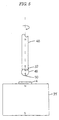
- Fig. 5 is a vertical cross section of an example of a typical holder for the present invention.
- Fig. 6 is a vertical cross section of another example of a holder for the present invention.
- Fig. 7 and 8 are a vertical cross section and the plan, respectively, that show another example of a lapping apparatus for quartz oscillators of the present invention.
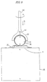
- Fig. 9 is a vertical cross section of another example for a lapping apparatus of quartz oscillators for the present invention.
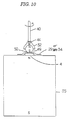
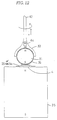
- Figs. 10-13 are vertical cross sections that show other examples of a lapping apparatus for quartz oscillators of the present invention.
- Fig. 14 is a vertical cross section of the lapped state of the present invention.
- Figs. 15-21 are vertical cross sections that show other examples of a lapping apparatus for quartz oscillators of the present invention.
- Figs. 22 and 23 are a vertical cross section and the plan, respectively, that show the magnetic table.
- Fig. 24 is a vertical cross section of the lapping apparatus for quartz.
- Fig. 25 is the plan of the plate.
- Fig. 26 is a vertical cross section of the lapping apparatus for said quartz.
- Fig. 27 is a vertical cross section of the magnetic plate for the present invention.
- Figs. 28-30 are vertical cross sections that show the lapping apparatus for quartz for the present invention.
- Figs. 31 and 32 are vertical cross sections of the spherical whetstone of the present invention.
- Figs. 33-36 are vertical cross sections that show the lapping apparatus for quartz of the present invention.
- Figs. 37-41 are vertical cross sections that show the object machined by the lapping process of the present invention.
- Figs. 42-44 are vertical cross sections that show a holding method example for lapped material of the present invention.
- Figs. 45-49 are a plan showing an example of the plastic part that holds the lapped material.
- Fig. 50 is a vertical cross section of the assembled state for the lapped material with a magnetic plate.
- Figs. 51 and 52 are the front view and the plan, respectively, that show the doughnut-shaped plate that connects the lapped material to the magnetic plate.
- Figs. 53 and 54 are vertical cross sections of the lapping apparatus for quartz of the present invention.
- Fig. 55 is a vertical cross section that shows the assembled state of the lapped material.
- Figs. 56-58 are vertical cross sections that show the lapping apparatus for quartz of the present invention.
- Figs. 59-61 are vertical cross sections that show one holding method for the lapped material.
- Fig. 62 is the plan for Fig. 61.
- Fig. 63 is a vertical cross section that shows another holding method for the lapped material.
- Fig. 64 is the plan for the lapping state during the starring motion (rotation and revolution) of the lapped material of the present invention.
- Fig. 65 illustrates the locus of the starring motion.
- Figs. 66 and 67 are vertical cross sections that show a holding example for the lapped material.
- Figs. 68 and 69 are cross sections that show the lapped state of the present invention.
- Figs. 70-73 are cross sections that show the lapped material after the lapping process of the present invention.
- Figs. 74-84 are diagrams of measured data for the lapped material in various shapes after executing the lapping by the manufacturing method of the present invention.
- Figs. 85-89 are diagrams of the reactance frequency characteristics actually measured for the quartz after the machining process.
- Figs. 1-15 are examples executed by the present invention.
- number 3 is the chuck
- 4 is the lapped material
- 12 is the lapping tool
- 14 is the adhesive
- 15 is the holding part
- 31 is the spherical whetstone
- 32 is the holder
- 33 is the adhesive film with a hole
- 34 is glass
- 35 is the table
- 36 is the grinding plate or diamond grain surface
- 37 is the hole
- 38 is the table in a vessel shape
- 39 is the cooling solvent
- 40 is the holder
- 41 is the lid
- 42 is the thin frozen layer
- 43 is the connection part
- 44 is the magnetic part
- 48 is the magnet holder
- 49 is the spherical whetstone for the spherical material
- 50 is the lapping agent for the magnetic material.
- Fig. 1 is a vertical cross section that shows the mechanism of the spherical whetstone 31 to lap the quartz.
- the spherical whetstone 31, whose diameter may range form approximately 1 mm to several cm, is made of nearly spherical iron steel or other materials.
- a lapping agent is coated with diamond grains or other substances by means of electric gilding, evaporation, CVD process, thermally solidified bond, thermally solidified metal, adhesive, or glue.
- the whetstone surface or the diamond grain surface 36 is formed.
- Figs. 2 and 3 are a vertical cross section and the plan, respectively, that show an example of holder 40 executed to hold the spherical whetstone 31.
- the holder part 32 of the holder 40 is shaped to be hemispherical in order to be able to support the upper half part of the spherical whetstone 31.
- the magnet part 44 is installed at the center of the holder 32.
- Fig. 4 shows the first example of a lapping machine for quartz oscillators.
- the magnetic induction of the table 35 supports the spherical whetstone 31 inside the holder 40 to lap the lapped material 4. Then, since the holder is to be rotated around the axis line by utilizing the spherical whetstone 31 with the holder 40, the center line of the spherical whetstone 31 always matches to the central axis of the holder 32, and the highest possible lapping accuracy can be achieved.
- Fig. 5 shows another example of the holder.
- the magnetic holder 48 can support the spherical whetstone 49 by means of the magnetic induction of the table 35.
- the shape of the holding part 32 of the magnetic holder 48 is that of a sphere, a cone, or a similar shape.
- the holding part 32 of spherical or conical shape supports the spherical material 49, and the spherical material 49 is lapped by the whetstone surface or diamond grains 50. Therefore, the center line of the spherical whetstone 49 is always equal to the central axis line of the spherical material 49, and the highest possible lapping accuracy can be achieved.
- Fig. 6 shows another example of the magnetic holder 48.
- the magnetic holder 48 supports the spherical whetstone 31 with the magnetic induction of the table 35.
- the holding part 32 for the magnetic holder 48 is spherical, conical, or of a similar shape. Since the surface of the whetstone 31 or diamond grain 36 laps the material by using the spherical or conical holder part 32 supporting the spherical whetstone 31, the center line of the spherical or conical holding part 32 always becomes the same as the center axis line of the spherical whetstone 31. The lapping accuracy is extremely high.
- Figs. 7 and 8 are a vertical cross section and the plan, respectively, that show another example of the lapping apparatus for quartz oscillators for the present invention.
- the adhesive file of the hole 37 is attached in order to machine solely the lapped material in the hole. Since the magnetic lapping agent 50 is attracted by the magnetic force on the surface of the spherical material 49, the holder 40 with the magnetic part 44 is installed at the center of the holding part 32 with the non-magnetic part.
- the lapped material 4 is rotated to be machined in the shape of a concave lens.
- Fig. 9 is a vertical cross section of another example of a lapping apparatus for quartz oscillators of the present invention.
- the lapped material 4 is installed on the table 35 made of a permanent magnet or an electric magnet, and an adhesive file 33 with a hole 37 is attached in order to machine solely the lapped material 4 in the hole.
- the lapped material 4 is rotated to be machined in a convex shape when the spherical whetstone 31 with the lapping surface or diamond grain surface 36 is installed by magnetic force to the holder 40, which has the magnetic part 44 at the center of the non-magnetic holding part 32.
- Figs. 10-13 are vertical cross sections of another example of a lapping apparatus for quartz oscillators of the present invention.
- the lapped material 4 is installed on the table 35 made of a permanent magnet or an electric magnet, and adhesive film 29 or glass 34 is attached in order to fix the lapped material 4.
- the spherical whetstone 31 or the spherical material 49 is held by the magnetic force of the magnetic induction by using the holder 40 which has the magnetic part 44 at the center of the holding part 32.
- the lapped material 4 is rotated to be machined in the shape of a concave lens.
- the lapped material 4 is also rotated by holding the table 35 with the chuck 3 of the lathe.
- Fig. 14 shows an example of the spherical whetstone 31, which is connected to the holder 40 by forming the adhesive part 43 with a screw, an adhesive agent, welding, or other means after matching the center line of the holder 40 to the spherical whetstone 31.
- the holder 40 is directly connected to the whetstone 31. It is used as said lapping apparatus.
- Fig. 15 shows an example of the spherical material 49 connected to the holder 32 by forming the adhesive part 43 with a screw, an adhesive agent, welding, or other means. This is done after the center line of the holding part 32, whose tip is cylindrical or another similar geometrical shape, matches the spherical whetstone 31.
- the holder 40 is directly connected to the spherical material 49.
- the diamond grains are fixed to the surface of the spherical material 49 by utilizing electric gilding, non-electric field gilding, or other techniques. This is used as the lapping apparatus.
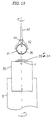
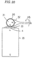
- Fig. 16 is a schematic diagram of the structural drawing of how to lap quartz oscillators.
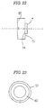
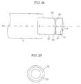
- Figs. 16, 17, 18, 19, 20, 21, 22, 24, 26, 27, 28, 29, and 30 are vertical cross sections.
- Figs. 23 and 25 are the plan.
- the number 3 is the chuck
- 4 is the lapped material
- 14 is the adhesive
- 31 is the spherical shaped whetstone
- 32 is the holding part
- 33 is the adhesive film with a hole
- 35 is the table
- 36 is the whetstone surface
- 40 is the holder 48 is the magnet holder
- 49 is the spherical material
- 51 is the table
- 52 is the air turbine
- 60 is the grooves.
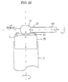
- Figs. 18, 26, 28, and 29 show the shaving or lapping state of the machined object while the spherical whetstone 31 is attracted and fixed to the end part of the magnet holder 4 by using the table 35 made of magnet or by the magnetic induction between the table 35 and the magnetic table 51.
- a lapped material such as quartz is attached on the table 35, which is comprised of the spherical magnet installed on the primary axis of the machine by means of the adhesive agent.
- the magnet holder 48 which is rotated by the air turbine 52, is installed perpendicular to or at an arbitrary angle to the machining axis.
- the spherical whetstone 31, whose surface is coated with diamond lapping grains, is attracted by magnetic induction. At the same time, the lapping primary axis rotates at a rate of approximately 300 rpm.
- the spherical whetstone 31 rotates at nearly 8,000 rpm.
- the lapped material 4 such as quartz as a heterogeneous crystal is shaved precisely and lapped between them.
- the diameter of the magnet holder 48 is smaller than that of the table 35, the magnetic flux between the spherical whetstone 31 and the magnet holder 48 is stronger than that between the spherical whetstone 31 and the table 35. Therefore, as the spherical whetstone 31 made of the magnet attracted to the end of the magnet holder 48 is in the shape of a cylinder or a similar geometrical shape, the spherical whetstone 31 and the magnet holder 48 are connected strongly. Moreover, the spherical whetstone 31 can be easily changed due to the magnetic induction of the ground table 35. Since the position of the spherical center is unchanged after the exchange, we can easily and effectively machine to shave at a high accuracy by using for finishing the fine spherical whetstone 31 after the coarse spherical whetstone 31.
- Figs. 22 and 23 show the side view and the back diagram, respectively, of the magnetic table 51, which is in the same cylindrical shape as that of the cylindrical table 35 made of the magnet.
- the back surface of the magnet table 51 has circular grooves.
- the lapped material 4 made of a heterogeneous material such as quartz is attached at the center with pine resin, and the pine resin is mixed with wax, or another resin.
- the grooves 60 are installed at the central part of the ground table 35.
- Fig. 25 is a side view diagram of the present lapping apparatus for quartz.
- the circular grooves 60, which are machined on the magnetic table 51, and the table 35 are used along with the spherical material 49.
- the center line of the magnet table 51 becomes equal to that of table 35 due to the principle of slide bearing.
- Fig. 26 shows the lapping configuration for the lapping apparatus for quartz.
- the magnetic table 51 attached to the lapped material 4 is connected to the central part of the table 35 installed at the side of the machining primary axis.
- the lapped material 4 is machined in the shape shown in Fig. 27. Again as shown in Fig.28, the central line of the magnet table 51 becomes equal to that of the lapped material 4.
- the lapped material 4 is attached with pine resin, pine resin mixed with wax, or another resin.
- the center line of the ground table 35 is equal to that of the magnet table 51 attached by facing the non-machined surface of the lapped material 4 as well as by using the magnetic table 51, the circular grooves around the table 35, and the spherical material 49. Then, the lapped material 4 is machined to shave by the spherical whetstone 31 and by rotating the non-machined surface of the spherical material 4 with the air turbine 52.
- Figs. 29 and 30 show the direct matching state between the center line of the table 35 and that of the magnetic table 51.
- the center line of the magnetic table 51 is directly connected to that of the chuck 3, and the lapped object 4 is machined to shave.
- Fig. 31 is a schematic diagram of the structural drawings of how to machine quartz oscillators.
- Figs. 31-41 are vertical cross sections.
- number 3 is the chuck
- 4 is the lapped material
- 5 is the vacuum chuck
- 14 is the adhesive
- 31 is the spherical whetstone
- 32 is the holding part
- 33 is the adhesive film with a hole
- 35 is the table
- 36 is the whetstone surface
- 48 is the magnet holder
- 49 is the spherical material
- 50 is the lapping grain.
- Figs. 31 and 32 show the state of the lapping surface 36, which is formed partially on the spherical whetstone 31 by electric gilding or non-electric gilding, on the spherical material 49. Also the whetstone surface 36 can be formed totally on the spherical whetstone 31.
- Figs. 33 and 34 show the shaving or lapping state of the lapped material 4 while the spherical whetstone 31 is attracted and fixed to the end part of the holder 32 at the tip of the magnet holder 48 by using the magnetic induction of the table 35 made of magnet.
- the spherical whetstone 31 held at the end of the magnet holder 48 rotates at over 10,000 rpm.
- the lapped material 4 is shaved and lapped by rotating it as shown in Figs. 33 and 34.
- the spherical whetstone 31 is attracted to the holder 32 at the end of the magnet holder 48 due to the magnetic induction of the table 35.
- Figs. 35 and 36 show the lapping and machining processes of the finished lapped material 12 in the shapes of convex and concave lenses.
- Figs. 37-41 show the finished lapped material 12, which is shaved and machined on the lapped material 4 by the spherical whetstone 31 in Figs. 30, 31 and 32 by the method seen in Figs. 14, 15, 16, 18, 28, 29, 33, 34, 35, and 36.
- Fig. 37 shows the finished lapped material 12 in a planar shape.
- Fig. 38 shows the finished lapped material 12 in a plano-convex shape, Fig. 39 in a convex lens shape, and Figs. 40 and 41 in a concave lens shape.
- Figs. 42 and 49 show the state of the lapped material 4 contacted and attached to the magnetic table 51 or a staggered magnetic table 93, whose U-shaped part is attached with a heated resin such as pine resin.
- the lapped material 4 is installed on the table. Pressure is imposed on the lapped material 4 by the magnetic force of the magnetic table 51 and the staggered magnetic table 93, as well as by using a cylindrical shaped object 66 or a cylindrical shaped magnet 67 on the cylindrical shaped object 66, which is made of iron capped by a plastic part 68 on the lapped material 4.
- the plastic part 68 at the end of the cylindrical object 66 or the cylindrical magnet 67 is made from polycarbonate or other materials.
- the central part of the plastic part 68 is in a hollow cylindrical shape. It is similar to a screw or a bolt. Then, the lapped material 4 is attached to the magnet table 51 by the pressure of the magnetic force from the magnet table 51, and even an extremely thin lapped material such as quartz cannot be ruptured.
- Fig. 43 shows the lapped material 4 connected to the plastic part 68 by the tip attraction pressure of the vacuum tube 69 through the hole 70 of the cylindrical object 66 or the cylindrical magnet 67.
- the magnetic table 51 is formed in a convex shape in order to ease the positioning of the attached lapped material 4.
- the lapped material 4 is attached with the adhesive 14 on the convex part.
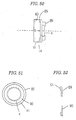
- Figs. 51 and 52 are, respectively, the front view and a cross section that show the doughnut-shaped table 89 used to connect the lapped material 4 to the magnetic table 51.
- Fig. 50 is a side view of the doughnut-shaped table 89, which is connected to the magnetic table 51.
- the doughnut-shaped table 89 is comprised of a sandwich structure of the thin, non-magnetic plate 90 and the magnetic ring 91.
- the heterogeneous crystal lapped material 4 is attached directly by the magnetic force of the magnetic table 51 to the surface center of the cylindrical magnetic table 51 similar to the diameter of magnetic cylindrical table 35, or else the lapped material 4 is attached by the surface tension of the water on the surface of a piece of wet suede 85 on the magnetic table 51.
- the lapped material 4 can be attached to the magnetic table 51 with pine resin or a mixed resin of wax and other materials.
- Fig. 53 shows the absorbed state of the magnetic table 51, which is attached to the lapped material 4, on the central part of the table 35, which is in a spherical shape and is installed at the side of the mechanical primary axis.
- the central axis of the magnetic table 51 is made identical to that of the table 35 by utilizing the principle of the slide bearing with the plural spherical objects 49 and grooves 60, which are machined on the circumference of the magnetic table 51 and the table 35.
- the central axis of the magnetic table 51 is matched to that of the lapping surface for the lapped material 4, and the lapped material 4 is attached on the magnetic table 51 by using resins etc. as shown in Fig. 55.
- the slide bearing principle that uses the spherical shaped material 49 and the grooves 60 made on the magnetic table 51 and the circumference of the table 35, the non-lapped surface of the lapped material 4 is machined by rotating the air turbine 52.
- Figs. 57 and 58 show the lapping process of the lapped material 4 when the magnetic table 51 is directly connected to the table 35, whose cylindrical shape is exactly identical to the magnetic table 51.
- Fig. 57 shows the lapping process of the lapped material 4 when the magnetic table 51 is attracted to the central axis of the magnetic chuck 3 by magnetic force.
- Fig. 58 shows the lapping state of the lapped material 4, where the spherical shaped whetstone 31 is supported by vacuum force by means of the magnetic holder 48 or the vacuum chuck 5 in a cylindrical or conical shape.
- Fig. 59 shows that the lapped material 4, where one side or both sides are shaved and lapped, is thickly attached with an adhesive 14 on the surface of the cylindrical shaped part 102.
- Fig. 59 also shows that the lapped material 4 becomes thicker when a ring-shaped holder 105, which is as thick as the lapped material 4 and is made from aluminum or other materials, is simply placed without the adhesive 14 around the exterior surface of the lapped material 4.
- One side is lapped with a cylindrical shaped part 102, which is made from plastics, metals such as aluminum and super steel, or other materials.
- the other side of the lapped material 4 is lapped with the ring-shaped holder 105 by using the carrier of a two-sided lapping machine. Then, the ultra thin example 12 can be easily lapped. Furthermore, the two-sided lapping machine enables the parallel, planer and flat surface to easily obtain higher accuracy.
- Fig. 60 shows that the circular U-shaped part 106, which is approximately as thick as or nearly as high as the lapped material 4 where one or both sides are lapped, is machined or molded by using plastics or metals such as aluminum.
- the lapped material 4 is attached with the adhesive 14 on part of the U-shaped part 106, or else the lapped material 4 is simply connected to the U-shaped part 106 without the adhesive 14.
- the exterior part of the lapped material 4 is formed and protected by the ring-shaped holder 105, whose height is equal to or less than that of the lapped material 4.
- a U-shaped part 106 makes the lapped material 4 thicker.
- the lapped material 4 is attached with the adhesive 14 on part of the U-shaped part 106 or it is simply connected without the adhesive 14.
- One side is lapped with the U-shaped part 106 made from plastics or metals such as aluminum by using the carrier of a two-sided lapping machine.
- the other side is lapped with both the lapped material 4 and the ring-shaped part of the U-shaped part 106 around the lapped material 4. Then, the ultra thin sample 12 is easily lapped in the way shown in Fig. 59.
- Figs. 61 and 62 show how the hollow cylindrical material 107 made from metals such as aluminum is placed on the lower surface of the lapping plate 62.
- the cylindrical material 108 is inserted into the hollow cylindrical material 107, which is a little shorter.
- the lapped material 4 is thicker because it is attached on the exterior surface of the cylindrical material 8 by the adhesive 14, or because the lapped material 4 is simply connected without the adhesive 14.
- the upper lapping plate 109 and the lower lapping plate 62 are used to employ the carrier of a two-sided lapping machine. As seen in Figs.
- the structure which is composed of the hollow cylindrical material 107, the cylindrical material 108, and the lapped material 4, rotates and revolves like a planet which rotates and revolves around the sun.
- One side laps the upper surface of the lapped material 4 with the lapping plate 109.
- the other side laps the lower side of the cylindrical material 108 by the lapping plate 62.
- the ultra thin lapped material 12 is easily machined.
- the reaction-frequency characteristics of the very thinly lapped material 12 show a spurious oscillation near the resonance region.
- the lapped material 12 shows an ideal reaction-frequency property with almost no spurious oscillation.
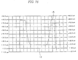
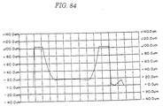
- Figs. 74-84 and Fig. 85 show the measured diagrams for a wide variety of the finished lapped material 12 such as quartz. These were obtained by the lapping method shown in Figs. 18, 56, 57, 58, 59, 60, and 63.
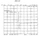
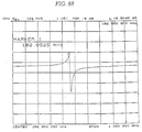
- Figs. 85-89 are measured diagrams of reaction-frequency properties for the finished lapped material 12 as quartz in Figs. 74 and 79.
- the measuring instrument used was a Hewlett Packard HP 8753C network analyzer.
- Fig. 85 shows the data of the finished lapped material 12 in Fig. 74.
- Figs. 86-89 show the data of the finished lapped material in Fig. 77.
- the measured data in Fig. 85 have quasi-frequency vibration with exterior spurious oscillation, which corresponds to the finished lapped material 12.
- the data in Figs. 85-89 have ideal frequency oscillation of reaction characteristics (impedance). This corresponds to the finished lapped material 12 in Figs. 77 and 74.
- the shape of the finished lapped material 12 in Fig. 77 was found to show a different property compared to that in Fig. 74.
- the shape of the finished lapped material 12 shown in Fig. 74 is planar (flat) at the oscillating part, and that the shape in Fig. 77 is plano-convex (one side is in a convex lens shape). Even in the case of the plano-convex shape, as seen in Figs. 80 and 81, the ultra thin finished lapped material 12 shown in Figs. 77-81 was found to show almost no spurious oscillation in the vicinity of the primary frequency when the thickness of the convex lens was less than 70 ⁇ m.
- the finished lapped material 12 should be less than 125 ⁇ m.
- a spherical whetstone made of a nearly spherical steel sphere is held freely by magnetic force at the tip of a spherical, cylindrical, or similarly shaped holder, and the whetstone can shave and lap a lapped material as thinly, minutely, and accurately as possible.
- Quartz oscillators and quartz resonators are required to be as small, thin, and accurate as possible. Conventional theories and machining methods cannot satisfy this requirement.
- the quartz oscillators and quartz resonators of this invention are manufactured without difficulty in quite thin, small, and accurate shapes. Therefore, quartz oscillators and quartz resonators are able to transmit and receive directly high frequency waves from 600 MHz to 1,000 MHz. This has been impossible with conventional technology.
- Mobile communication devices such as mobile telephones can be entirely digitized. Those devices can be made as small as business cards.
- the present invention can be applied to a wide variety of domains such as small high-resolution radar, small radar that automatically stops cars, tiny radar such as robot eyes, small radar for blind people, high resolution electronic microscopes, communication satellites, as well as other domains.
- quartz oscillators as the lapped material are shaved or lapped by a rotating holding tool directly connected to the holder after forming an adhesive part on the spherical whetstone, on which a diamond grain surface is made in a purely spherical or nearly spherical shape.
- the spherical whetstone is made of nearly spherical iron steel in which the diameter ranges from approximately 1 mm to several cm.
- a lapping agent is coated with grains of diamond or other substances by means of electric gilding, evaporation, CVD process, etc., and the whetstone surface or the diamond grain surface is formed.
- This novel structure which is composed of the hollow cylindrical shaped material, the cylindrical shaped material, and the lapped material, rotates and revolves as a planet.
- One side laps the upper surface with the lapping plate.
- the other side laps the lower side of the cylindrical material with the lapping plate.
- An ultra thin material is easily machined. Magnetic force is used to attract the lapped material to the lapping plate. The merits that occur are listed below.
- the lapped material becomes thicker where a ring-shaped holder is placed without an adhesive around the exterior surface of the lapped material.
- One side is lapped with the cylindrical shaped part (the so-called "menko” in Japanese).
- the other side is lapped with a ring-shaped holder by using the carrier of a two-sided lapping machine.
- An ultra thin sample can be easily lapped.
- the circular U-shaped part which is approximately as thick as or nearly as high as the lapped material, is machined or molded by using plastics or metals.
- the lapped material is attached with an adhesive on part of the U-shaped part, or the lapped material is connected to it without an adhesive.
- the exterior part of the lapped material is formed and protected by the ring-shaped part, and the U-shaped part makes the lapped material thicker. This is because the lapped material is attached with an adhesive on part of the U-shaped part, or it is simply connected without an adhesive.
- One side is lapped with the ring-shaped part of the U-shaped part by using the carrier of a two-sided lapping machine. The other side is lapped with both the lapped material and with the ring-shaped part of the U-shaped part around the lapped material.
- An ultra thin sample is easily lapped by overcoming the defects of the conventional lapping machine as explained below.
- Quartz oscillators are lapped while the magnetic part of the spherical material, on which the whetstone surface or the diamond grain surface on the spherical shaped whetstone is formed, is magnetized.
- the lapped object is machined to be partly planar at the central part of said lapped material in the shape of a convex or concave lens. This is accomplished by the circular surface of said spherical whetstone, whose lapping surface is made by electric gild or non-electric gild on the spherical material.
- the present invention can be applied to a wide variety of electronic apparatuses, communication instruments such as mobile telephones and small high resolution radars, and other things that utilize quartz oscillators and quartz resonators in order to transmit and receive stable high frequency waves.
Landscapes
- Engineering & Computer Science (AREA)
- Mechanical Engineering (AREA)
- Manufacturing & Machinery (AREA)
- Finish Polishing, Edge Sharpening, And Grinding By Specific Grinding Devices (AREA)
- Grinding And Polishing Of Tertiary Curved Surfaces And Surfaces With Complex Shapes (AREA)
Applications Claiming Priority (5)
| Application Number | Priority Date | Filing Date | Title |
|---|---|---|---|
| JP357431/96 | 1996-12-06 | ||
| JP35743196A JPH10173462A (ja) | 1996-12-06 | 1996-12-06 | 水晶振動子の製造方法 |
| JP233221/97 | 1997-07-26 | ||
| JP23322197A JPH1142559A (ja) | 1997-07-26 | 1997-07-26 | 水晶振動子の製造方法 |
| PCT/JP1997/002860 WO1998024588A1 (fr) | 1996-12-06 | 1997-08-18 | Procede et appareil de production d'un oscillateur a quartz |
Publications (2)
| Publication Number | Publication Date |
|---|---|
| EP0884133A1 true EP0884133A1 (fr) | 1998-12-16 |
| EP0884133A4 EP0884133A4 (fr) | 2000-11-29 |
Family
ID=26530922
Family Applications (1)
| Application Number | Title | Priority Date | Filing Date |
|---|---|---|---|
| EP97935811A Withdrawn EP0884133A4 (fr) | 1996-12-06 | 1997-08-18 | Procede et appareil de production d'un oscillateur a quartz |
Country Status (3)
| Country | Link |
|---|---|
| US (1) | US6203644B1 (fr) |
| EP (1) | EP0884133A4 (fr) |
| WO (1) | WO1998024588A1 (fr) |
Cited By (1)
| Publication number | Priority date | Publication date | Assignee | Title |
|---|---|---|---|---|
| CN109333166A (zh) * | 2018-09-26 | 2019-02-15 | 南阳富新特光电科技有限公司 | 一种球面玻璃加工工艺 |
Families Citing this family (19)
| Publication number | Priority date | Publication date | Assignee | Title |
|---|---|---|---|---|
| AU2003272073A1 (en) * | 2003-05-30 | 2005-01-21 | Arvindbhai Lavjibhai Patel | A novel laser bruting machine |
| US8778323B2 (en) | 2006-05-03 | 2014-07-15 | L'oréal | Cosmetic compositions containing block copolymers, tackifiers and modified silicones |
| US8673283B2 (en) | 2006-05-03 | 2014-03-18 | L'oreal | Cosmetic compositions containing block copolymers, tackifiers and a solvent mixture |
| US8673282B2 (en) | 2006-05-03 | 2014-03-18 | L'oreal | Cosmetic compositions containing block copolymers, tackifiers and a selective solvent for soft blocks |
| US8557230B2 (en) | 2006-05-03 | 2013-10-15 | L'oreal | Cosmetic compositions containing block copolymers, tackifiers and shine enhancing agents |
| US8758739B2 (en) | 2006-05-03 | 2014-06-24 | L'oreal | Cosmetic compositions containing block copolymers, tackifiers and gelling agents |
| US8603444B2 (en) | 2007-01-12 | 2013-12-10 | L'oréal | Cosmetic compositions containing a block copolymer, a tackifier and a high viscosity ester |
| US8658141B2 (en) | 2007-01-12 | 2014-02-25 | L'oreal | Cosmetic composition containing a block copolymer, a tackifier, a silsesquioxane wax and/or resin |
| US20120219516A1 (en) | 2011-02-25 | 2012-08-30 | L'oreal S.A. | Cosmetic compositions having long lasting shine |
| CN103033898B (zh) * | 2011-09-30 | 2016-08-10 | 鸿富锦精密工业(深圳)有限公司 | 镜头点胶装置及镜头点胶方法 |
| US10272579B2 (en) | 2012-05-25 | 2019-04-30 | Shavelogic, Inc. | Magnetic attachment for shaving cartridge |
| US8789282B2 (en) | 2012-05-25 | 2014-07-29 | Shavelogic, Inc. | Magnetic attachment for shaving cartridge |
| US20140116211A1 (en) | 2012-10-25 | 2014-05-01 | Shavelogic, Inc. | Dedicated Attachment Systems for Consumer Products |
| US20160121498A1 (en) * | 2014-10-30 | 2016-05-05 | The Gillette Company | Shaving razor system including at least one magnetic element |
| US20160121496A1 (en) * | 2014-10-30 | 2016-05-05 | The Gillette Company | Shaving razor system including at least one magnetic element |
| US20160121495A1 (en) * | 2014-10-30 | 2016-05-05 | The Gillette Company | Shaving razor system including at least one magnetic element |
| US20160121497A1 (en) * | 2014-10-30 | 2016-05-05 | The Gillette Company | Shaving razor system including at least one magnetic element |
| CN109483394B (zh) * | 2018-09-13 | 2023-12-12 | 西安航晨机电科技股份有限公司 | 半球谐振子超精密球面加工装置及加工方法 |
| CN115741389B (zh) * | 2022-11-21 | 2025-09-26 | 中国船舶集团有限公司第七〇七研究所 | 一种半球谐振子超精密磨削加工装置及加工方法 |
Family Cites Families (12)
| Publication number | Priority date | Publication date | Assignee | Title |
|---|---|---|---|---|
| US4240311A (en) * | 1978-12-18 | 1980-12-23 | Motorola, Inc. | Quartz crystal resonator |
| JPS5928768Y2 (ja) * | 1980-06-17 | 1984-08-18 | 株式会社東芝 | 研摩工具 |
| JPS5739175A (en) * | 1980-08-19 | 1982-03-04 | Citizen Watch Co Ltd | Sizing method in one side polishing processing |
| JPS59191251A (ja) * | 1983-04-14 | 1984-10-30 | Hitachi Ltd | 雰囲気試料運搬室 |
| JPS59191251U (ja) * | 1983-06-03 | 1984-12-19 | 株式会社東芝 | 研摩材 |
| JPS60170313A (ja) * | 1984-02-14 | 1985-09-03 | Matsushima Kogyo Co Ltd | 圧電発振片の製造方法 |
| JPS6279931A (ja) * | 1985-10-02 | 1987-04-13 | Mitsubishi Heavy Ind Ltd | 非磁性体ワ−ク用のワ−クチヤツクプレ−ト |
| JPH0818241B2 (ja) * | 1987-03-19 | 1996-02-28 | キヤノン株式会社 | 研磨工具の製造方法 |
| JP2624248B2 (ja) * | 1987-03-19 | 1997-06-25 | キヤノン株式会社 | 計測研磨装置 |
| JPH01166061U (fr) * | 1988-05-11 | 1989-11-21 | ||
| US5702294A (en) * | 1989-06-19 | 1997-12-30 | Constant Velocity Systems, Inc. | Grinding bit having a novel grinding grip |
| US5681209A (en) * | 1996-01-29 | 1997-10-28 | Constant Velocity Systems, Inc. | Housing grinding machine |
-
1997
- 1997-08-18 EP EP97935811A patent/EP0884133A4/fr not_active Withdrawn
- 1997-08-18 WO PCT/JP1997/002860 patent/WO1998024588A1/fr not_active Ceased
- 1997-08-18 US US09/117,025 patent/US6203644B1/en not_active Expired - Fee Related
Non-Patent Citations (2)
| Title |
|---|
| No further relevant documents disclosed * |
| See also references of WO9824588A1 * |
Cited By (2)
| Publication number | Priority date | Publication date | Assignee | Title |
|---|---|---|---|---|
| CN109333166A (zh) * | 2018-09-26 | 2019-02-15 | 南阳富新特光电科技有限公司 | 一种球面玻璃加工工艺 |
| CN109333166B (zh) * | 2018-09-26 | 2020-08-04 | 南阳富新特光电科技有限公司 | 一种球面玻璃加工工艺 |
Also Published As
| Publication number | Publication date |
|---|---|
| EP0884133A4 (fr) | 2000-11-29 |
| WO1998024588A1 (fr) | 1998-06-11 |
| US6203644B1 (en) | 2001-03-20 |
Similar Documents
| Publication | Publication Date | Title |
|---|---|---|
| US6203644B1 (en) | Method and apparatus for manufacture of quartz oscillator | |
| EP1326293A1 (fr) | Dispositif piezoelectrique et transducteur electroacoustique et leur procede de production | |
| US6428399B1 (en) | Polishing apparatus for polishing a hard material-coated wafer | |
| CN113523968B (zh) | 石英半球谐振子激光和超声辅助磨削制造装备及其方法 | |
| CN110198809A (zh) | 通过调制磁场角度或强度的对可磁化磨料颗粒的操纵 | |
| Guo et al. | Novel localized vibration-assisted magnetic abrasive polishing method using loose abrasives for V-groove and Fresnel optics finishing | |
| CN117226440B (zh) | 一种二件套半球谐振陀螺的谐振子构型及其加工方法 | |
| CN205237716U (zh) | 磁流变柔性抛光垫的动态磁场自锐抛光装置 | |
| EP0337575A2 (fr) | Transducteur à ultrason et son procédé de production | |
| WO2006126302A1 (fr) | Outil de decoupage et dispositif de decoupage qui ont une lame de decoupage de type disque | |
| CN119714356A (zh) | 一种半球谐振子全球面质量-刚度联合修调方法及系统 | |
| CN112658818A (zh) | 一种用于晶圆超精密加工的超声振动辅助磨削装置 | |
| CN100432004C (zh) | 压电陶瓷球壳制作方法 | |
| Li et al. | A batch-mode micromachining process for spherical structures | |
| CN108161219A (zh) | 一种用于激光加工设备的新型振镜 | |
| CN106493648A (zh) | 一种径向超声振动辅助杯形砂轮及其使用方法 | |
| CN112548848B (zh) | 一种承载头和化学机械抛光设备 | |
| CN210550372U (zh) | 一种用于化学机械抛光的承载头及化学机械抛光设备 | |
| CN116213232B (zh) | 一种超声扭振装置 | |
| EP1168464A1 (fr) | Element piezo-electrique et procede de production | |
| US4240311A (en) | Quartz crystal resonator | |
| CN117161992B (zh) | 一种基于径向跳动量在位监测的永磁半球端抛光头粘接工艺方法 | |
| Xue et al. | Precision polishing of the mandrel for X-ray grazing incidence mirrors in the Einstein probe | |
| Riveros et al. | Development of an alternating magnetic-field-assisted finishing process for microelectromechanical systems micropore x-ray optics | |
| Greger et al. | Development of technology for lightweight Beryllium Cassegrain Telescope for space applications and lessons learnt |
Legal Events
| Date | Code | Title | Description |
|---|---|---|---|
| PUAI | Public reference made under article 153(3) epc to a published international application that has entered the european phase |
Free format text: ORIGINAL CODE: 0009012 |
|
| 17P | Request for examination filed |
Effective date: 19980805 |
|
| AK | Designated contracting states |
Kind code of ref document: A1 Designated state(s): DE FR GB SE |
|
| A4 | Supplementary search report drawn up and despatched |
Effective date: 20001018 |
|
| AK | Designated contracting states |
Kind code of ref document: A4 Designated state(s): DE FR GB SE |
|
| 17Q | First examination report despatched |
Effective date: 20010927 |
|
| STAA | Information on the status of an ep patent application or granted ep patent |
Free format text: STATUS: THE APPLICATION IS DEEMED TO BE WITHDRAWN |
|
| 18D | Application deemed to be withdrawn |
Effective date: 20030301 |