EP0884154A2 - Formspannvorrichtung - Google Patents
Formspannvorrichtung Download PDFInfo
- Publication number
- EP0884154A2 EP0884154A2 EP98304539A EP98304539A EP0884154A2 EP 0884154 A2 EP0884154 A2 EP 0884154A2 EP 98304539 A EP98304539 A EP 98304539A EP 98304539 A EP98304539 A EP 98304539A EP 0884154 A2 EP0884154 A2 EP 0884154A2
- Authority
- EP
- European Patent Office
- Prior art keywords
- lower mold
- mold plate
- lower platen
- platen
- contractible member
- Prior art date
- Legal status (The legal status is an assumption and is not a legal conclusion. Google has not performed a legal analysis and makes no representation as to the accuracy of the status listed.)
- Withdrawn
Links
- 230000000712 assembly Effects 0.000 description 12
- 238000000429 assembly Methods 0.000 description 12
- 230000008859 change Effects 0.000 description 7
- 238000004519 manufacturing process Methods 0.000 description 7
- 230000007246 mechanism Effects 0.000 description 7
- 238000010276 construction Methods 0.000 description 3
- 230000000694 effects Effects 0.000 description 3
- 210000003414 extremity Anatomy 0.000 description 3
- 230000008439 repair process Effects 0.000 description 3
- 230000008602 contraction Effects 0.000 description 1
- 238000006073 displacement reaction Methods 0.000 description 1
- 238000010438 heat treatment Methods 0.000 description 1
- 238000003780 insertion Methods 0.000 description 1
- 230000037431 insertion Effects 0.000 description 1
- 238000009434 installation Methods 0.000 description 1
- 238000000034 method Methods 0.000 description 1
- 238000012986 modification Methods 0.000 description 1
- 230000004048 modification Effects 0.000 description 1
- 230000008569 process Effects 0.000 description 1
- 230000000717 retained effect Effects 0.000 description 1
- 230000007704 transition Effects 0.000 description 1
- 210000001364 upper extremity Anatomy 0.000 description 1
- 238000005303 weighing Methods 0.000 description 1
Images


Classifications
-
- B—PERFORMING OPERATIONS; TRANSPORTING
- B29—WORKING OF PLASTICS; WORKING OF SUBSTANCES IN A PLASTIC STATE IN GENERAL
- B29C—SHAPING OR JOINING OF PLASTICS; SHAPING OF MATERIAL IN A PLASTIC STATE, NOT OTHERWISE PROVIDED FOR; AFTER-TREATMENT OF THE SHAPED PRODUCTS, e.g. REPAIRING
- B29C33/00—Moulds or cores; Details thereof or accessories therefor
- B29C33/30—Mounting, exchanging or centering
- B29C33/305—Mounting of moulds or mould support plates
-
- B—PERFORMING OPERATIONS; TRANSPORTING
- B29—WORKING OF PLASTICS; WORKING OF SUBSTANCES IN A PLASTIC STATE IN GENERAL
- B29L—INDEXING SCHEME ASSOCIATED WITH SUBCLASS B29C, RELATING TO PARTICULAR ARTICLES
- B29L2030/00—Pneumatic or solid tyres or parts thereof
Definitions
- the present invention relates generally to apparatus for detachably retaining mold sections for producing tires in a tire curing press. More particularly, the present invention relates to a mold clamping system for selectively retaining and releasing a lower mold section for tires with respect to a tire curing press. More specifically, the present invention relates to a mold clamping system for aligning and temporarily retaining a lower mold section for tires in a tire curing press which permits quick change to a different lower mold section for a tire having a different size and/or different tread pattern.
- mold retaining devices have been employed for detachably securing mold sections in tire curing presses.
- Some type of mold retaining device was necessary to maintain the molds attached to the platens for travel therewith during the opening and closing of the press for the insertion of an uncured tire into position between the mold sections and the removal of the tire from between the mold sections subsequent to the curing operation.
- the mold sections retain a predetermined position during repeated curing operations and be sufficiently firmly attached to the platens, such that the mold sections can withstand the stripping operation of separating the cured tire from the mold sections subsequent to the curing operation.
- mold change operations have presented a serious safety hazard.
- Mold sections for small passenger car size tires up through large truck tires employ molds weighing from hundreds to thousands of pounds.
- the necessity for press operators to be within the mold cavities for removing and inserting bolts poses a substantial safety risk should the upper mold section be accidentally dropped or should a tire curing press accidentally cycle from the fully open to the closed position.
- the conventional usage of bolts for mounting mold sections in a tire curing press has produced a significant continuing safety hazard over the years.
- lower mold clamping devices hydraulically actuated lever arms have been proposed which project radially outwardly from the lower platen and bolster area to provide a clamping element movable into and out of engagement with a circumferential notch in the lower mold section or the mold plate therefor.
- Even more elaborate lower mold clamping devices have been proposed which employ parallelogram linkage devices that have circumferentially-located centering members that engage centering members on the circumferential outside surface of a lower mold section.
- bearings have been employed to support the lower mold section to permit the centering movement of the lower mold section.
- These lower mold clamping devices are normally cylinder actuated and provide a clamping element for securing a mold once it has been centered to a concentrically aligned position with the lower mold cavity and platen.
- lower mold clamping devices have not received wide acceptance because they are relatively complex and, as a result, expensive.
- some or these lower mold clamping devices include substantial structure which projects radially outwardly from the lower platen bolster and mold areas, such that they are prone to interference with other press operating mechanisms, can be easily damaged, or can themselves constitute an extent of safety hazard to operating personnel endeavoring to service or repair a tire curing press. Accordingly, conventional bolts remain in common use for retaining lower mold sections in tire curing presses.
- a further object of the present invention is to provide such a clamping system which is capable of effecting rapid release of a clamped lower mold section and the alignment and clamping of a different lower mold section to effect mold change in a press in a convenient manner and in a minimum of time such as to minimize down time of a tire curing press during the mold change operation to produce a different tire.
- Another object of the present invention is to provide a lower mold clamping system which is positioned essentially within the confines of the lower platen bolster and housing of a tire curing press.
- a further object of the present invention is to provide such a mold clamping system which is located so as not to interfere with other press operating mechanisms, which is protected from accidental damage, and which does not interfere with service or repair of the press.
- Yet another object of the present invention is to provide such a mold clamping system which does not require manual operations by press operating personnel in the mold area between the upper and lower mold sections.
- Another object of the present invention is to provide a lower mold clamping system which promotes easy location and seating of a lower mold section in its aligned position on the lower platen of a press.
- a further object of the present invention is to provide such a lower mold clamping system which mechanically clamps the lower mold section in its operating position.
- a further object of the present invention is to provide such a mold clamping system which may be employed with any type of upper mold clamping system currently used in the industry.
- Still another object of the present invention is to provide such a mold clamping system which is of relatively simple construction, is easy to install on new presses or as a retrofit for existing presses, and otherwise constitutes an advantageous contribution to the art without the drawbacks of more complex systems which have been proposed.
- the present invention contemplates mold clamping apparatus for selectively detachably securing a lower mold plate mounting a lower mold section relative to the lower platen, lower bolster and lower housing of a tire curing press, including a plurality of bores extending through the lower platen, the lower bolster and the lower housing, a tapered bore in the lower mold plate, a locking rod positioned in each of the bores and extending into the tapered bore, a contractible member affixed to the lower platen and extending into the tapered bore when the lower mold plate is seated on the lower platen, a jam nut mounted on the locking rod movable into and out of engagement with the contractible member, and a biasing element urging the jam nut into contact with the contractible member for locking the contractible member in the tapered bore to secure the lower mold plate to the lower platen.
- Fig. 1 is a fragmentary, vertical sectional view of a lower mold cavity of an exemplary tire curing press taken substantially along the line 1-1 of Fig. 6 showing the arrangement of a mold clamping assembly according to the concepts of the present invention in relation to principal press components.
- Fig. 2 is an enlarged, fragmentary, vertical sectional view of the mold clamping assembly of Fig. 1 positioned to receive a lower mold plate thereon.
- Fig. 3 is an enlarged, fragmentary, vertical sectional view similar to Fig. 2 of the mold clamping assembly depicting the mold plate being fitted over the upper extremity of the mold clamping assembly and aligned with the platen of the tire curing press.
- Fig. 4 is an enlarged, fragmentary, vertical sectional view of the mold clamping assembly, taken substantially along the line 4-4 of Fig. 1, and similar to Figs. 2 and 3, showing the mold plate clamped to the platen of the tire curing press in the position employed for operation of the tire curing press.
- Fig. 5 is an enlarged, exploded perspective view of an operating portion of the mold clamping assembly showing details of the spring collet mechanism and the locking nut which operatively interrelates therewith.
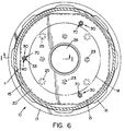
- Fig. 6 is a top plan view taken substantially along line 6-6 of Fig. 1 of a lower mold cavity of a tire curing press showing an exemplary location of a plurality of mold clamping assemblies.
- FIG. 10 A portion of an exemplary tire curing press utilizing the concepts of the present invention is generally indicated by the numeral 10 in Figs. 1 and 6 of the drawings. While a type of press commercialized in the industry by Applicants' assignee is depicted for exemplary purposes, it will be appreciated that the concepts of the present invention may be readily adapted to a variety of types and sizes of tire curing presses.
- a tire curing press lower mold cavity area is depicted.
- the lower mold cavity 11 is generally defined by a lower press housing 12 which is supported by a press base (not shown).
- a cylindrical wall 13 Extending upwardly from lower press housing 12 is a cylindrical wall 13 which peripherally defines the lower mold cavity 11.
- the cylindrical wall 13 has a lower flange or lip 14 which extends radially outwardly of lower mold cavity 11.
- An upper cylindrical shell 15 is located above the cylindrical wall 13 and similarly encompasses an upper mold section and related components suspended from a press cross beam (not shown).
- the cylindrical shell 15 has an upper flange 16 which is selectively interengaged with the lower flange or lip 14 by a locking ring 17 which may be journaled on lower flange 14 for maintaining the press 10 locked in a closed position during the tire curing operation. Additional details of tire curing presses of this general type are shown in U.S. Patent No. 4,332,536 and patents referred to therein.
- a lower mold plate 20 Positioned centrally of the cylindrical wall 13 in the lower mold cavity 11 are support components for an exemplary lower mold section M.
- a lower mold plate 20 Directly underlying and supporting the lower mold section M is a lower mold plate 20.
- the lower mold section M may be attached to the lower mold plate 20 by a plurality of bolts (not shown).
- the lower mold section M and the lower mold plate 20 may be formed as a single unit.
- the combined lower mold section M and lower mold plate 20 are replaced in the tire curing press 10 when a mold change is effected to produce a different tire configuration.
- Underlying and supporting the lower mold plate 20 is a lower platen 21 which may be of any desired conventional construction.
- the lower platen 21 is attached to a lower bolster 22 as by a plurality of suitable fasteners 23.
- the lower platen 21 may be spaced from the lower bolster 22 by a lower insulating layer 24 whereby the transfer of heat from the lower platen 21 is primarily to the lower mold plate 20 and the lower mold section M.
- the lower bolster 22 is supported by rods of squeeze cylinders or adjusting screws (not shown) to which it is attached by fasteners 25.
- the lower mold section M, lower mold plate 20, lower platen 21, and lower bolster 22 are of a generally annular configuration to form a circular central cavity 26 that receives a center mechanism (not shown) which may be any of numerous types known in the art.
- a center mechanism (not shown) which may be any of numerous types known in the art.
- the above-described press environment constitutes merely an example of one type of tire curing press to which the concepts of the present invention may be applied.
- Mold clamping assemblies are shown in Figs. 1-4 and 6 of the drawings. Figs. 1 and 6 particularly depict the position of the mold clamping assemblies 30 in relation to the overall structure of the tire curing press 10. As seen, the mold clamping assemblies 30 are positioned radially proximate the outer periphery of lower platen 21 and in a plurality of locations circumferentially of lower platen 21. Fig. 6 shows three equiangularly-spaced mold clamping assemblies 30 arranged about the lower platen 21. It is to be appreciated that four or more mold clamping assemblies 30 may be provided for a particular platen 21, depending upon the size, construction, and loading parameters on lower platen 21 and mold clamping assemblies 30 of a particular press configuration. Since all of the three mold clamping assemblies 30 may be structurally and operationally identical, only a single mold clamping assembly 30 is hereinafter detailed.
- the locking rod 31 Central to mold clamping assembly 30 is a locking rod, generally indicated by the numeral 31, as may be seen in Figs. 1 and 2.
- the locking rod 31 has an elongate shaft 32 which extends through multi-size bores 21', 22', and 24' in the lower platen 21, the lower bolster 22, and the lower insulating layer 24, respectively.
- the shaft 32 of locking rod 31 is of such a length as to extend upwardly beyond lower platen 21 and below bolster 22.
- the upper axial extremity of shaft 32 has a jam nut 33 rigidly attached thereto.
- the jam nut 33 has a beveled outer surface 34 which is of progressively larger diameter axially upwardly of the jam nut 33, as best seen in Fig. 2.
- the mold clamping assembly 30 also includes a contractible gripping assembly, generally indicated by the numeral 40.
- the contractible gripping assembly 40 supports and interacts with the locking rod 31 to control operation of the mold clamping assembly 30.
- the primary operative component of contractible gripping assembly 40 is a spring collet, generally indicated by the numeral 41, which is best seen in Figs. 2 and 5 of the drawings.
- the spring collet 41 has a circular base 42, which is accommodated in a bore 21' of lower platen 21.
- the circular base 42 has a central aperture 43 adapted to slidingly receive the shaft 32 of the locking rod 31.
- the spring collet 41 has an annular wall 44 projecting axially from the circular base 42 radially outwardly of the aperture 43.
- the annular wall 44 is circumferentially discontinuous in having a plurality of axial slots 45 which preferably extend substantially the entire length of annular wall 44.
- the axial slots 45 permit the annular wall 44 to radially contract or depress from the normal position depicted in Figs. 2 and 5 upon application of radial forces about the annular wall 44.
- the contracted position of the annular wall 44 of spring collet 41 is depicted in Fig. 3 of the drawings.
- the annular wall 44 of contractible gripping assembly 40 is splayed radially outwardly proximate the end displaced from circular base 42 to form a tapered inner surface 46.
- the tapered inner surface 46 becomes progressively diametrically larger proximate the upper end of spring collet 41 and is preferably angularly oriented to substantially parallel and thus matingly engage the beveled surface 34 of jam nut 33 when in engagement therewith, as depicted in Fig. 4 of the drawings.
- the annular wall 44 of spring collet 41 is also provided with a tapered outer surface 47 which may conveniently parallel the tapered inner surface 46 and serves a purpose hereinafter detailed.
- the upper axial extremity of annular wall 44 of spring collet 41 has a reverse taper lead surface 48 which serves a purpose hereinafter detailed.
- Spring collet 41 of contractible gripping assembly 40 is positioned and retained in an annular collet housing 50 which surrounds a portion of the spring collet 41.
- collet housing 50 encompasses the annular wall 44 of spring collet 41 in the area proximate the circular base 42 and engages the circular base 42 to apply an axial seating force thereto.
- the collet housing 50 has external threads 51 adapted to matingly engage threads 52 on the bore 21' in platen 21 to effect positioning of spring collet 41 and to permit disassembly of contractible gripping assembly 40 in the event repair or replacement of the various components is necessary.
- the rod biasing assembly 55 includes a coil spring 56 which is telescoped over the shaft 32 of the locking rod 31 and is of a larger internal diameter than the external diameter of the shaft 32. As shown, the coil spring 56 is interposed between the circular base 42 which is in a fixed position and a spring keeper 57 that engages a split ring 58 which is located in a fixed position axially of the shaft 32.
- the rod biasing assembly 55 thus normally biases the shaft 32 of locking rod 31 to the position depicted in Fig. 4 with the jam nut 33 retracted within and engaging the spring collet 41, thus locking lower mold plate 20 in clamped position on the lower platen 21.
- the rod actuation assembly 60 consists of a fluid-actuated cylinder 61 having a projecting cylinder rod 62 which extends through a bore 12' in lower housing 12 of the tire curing press 10 in concentric alignment with the shaft 32 of locking rod 31.
- the cylinder 61 may have a projecting threaded sleeve 63 which engages internal threads 64 in bore 12' in the lower press housing 12 to maintain cylinder 61 in fixed position relative to the lower press housing 12.
- the cylinder rod 62 When the cylinder rod 62 is in the fully retracted position, it is preferably slightly axially spaced from shaft 32 to ensure that rod biasing assembly 55 has moved jam nut 33 of locking rod 31 to the lowermost seated position seen in Fig. 4 to effect maximum clamping of the lower mold plate 20.
- the cylinder 61 is actuated to extend the cylinder rod 62 only for purposes of releasing jam nut 33 from spring collet 41 prior to lifting of the lower mold plate 20 relative to the lower platen 21 and to maintain the gripping assembly 40 in the position depicted in Fig.
- the lower mold plate 20 is provided with receivers, generally indicated by the numeral 70.
- receivers 70 In the exemplary embodiment shown in the drawings, three receivers 70 (Fig. 2) would be positioned concentric with the three mold clamping assemblies 30 located as seen in Fig. 6.
- each receiver 70 has a tapered bore 71 which substantially parallels the tapered outer surface 47 of annular wall 44 of gripping assembly 40 when lower mold plate 20 is in the clamped position depicted in Fig. 4 of the drawings.
- Lower mold plate 20 is also provided with a platen-engaging surface 72 having as an entry to receiver 70 a reverse taper receiving surface 73 which is adapted to engage reverse taper lead surface 48 at the extremity of annular wall 44 of spring collet 41.
- Reverse taper receiving surface 73 preferably substantially angularly parallels reverse taper lead surface 48 so as to guide receiver 70 and thus lower mold plate 20 as it is lowered into engagement with gripping assembly 40.
- Continued lowering of lower mold plate 20 results in radial contraction of spring collet 41 until reverse taper receiving surface 73 passes an inner apex 74 in receiver 70, which is the transition point between tapered bore 71 and reverse taper receiving surface 73.
- With lower mold plate 20 thus aligned with gripping assembly 40 further lowering of lower mold plate 20 toward lower platen 21 results in expansion of spring collet 41 and seating of jam nut 33 within spring collet 41 when cylinder rod 62 is retracted to allow the rod biasing assembly 55 to act on locking rod 31.
- any number of mold clamping assemblies 30 employed for a particular lower mold plate 20 may simultaneously actuate as the lower mold plate 20 with attached lower mold section M is lowered into a tire curing press 10 and prior to removal of a lower mold plate 20.
Landscapes
- Engineering & Computer Science (AREA)
- Mechanical Engineering (AREA)
- Moulds For Moulding Plastics Or The Like (AREA)
- Heating, Cooling, Or Curing Plastics Or The Like In General (AREA)
Applications Claiming Priority (2)
| Application Number | Priority Date | Filing Date | Title |
|---|---|---|---|
| US08/873,317 US5773041A (en) | 1997-06-11 | 1997-06-11 | Mold clamping system |
| US873317 | 1997-06-11 |
Publications (2)
| Publication Number | Publication Date |
|---|---|
| EP0884154A2 true EP0884154A2 (de) | 1998-12-16 |
| EP0884154A3 EP0884154A3 (de) | 2000-11-22 |
Family
ID=25361393
Family Applications (1)
| Application Number | Title | Priority Date | Filing Date |
|---|---|---|---|
| EP98304539A Withdrawn EP0884154A3 (de) | 1997-06-11 | 1998-06-09 | Formspannvorrichtung |
Country Status (3)
| Country | Link |
|---|---|
| US (1) | US5773041A (de) |
| EP (1) | EP0884154A3 (de) |
| CA (1) | CA2240055A1 (de) |
Families Citing this family (9)
| Publication number | Priority date | Publication date | Assignee | Title |
|---|---|---|---|---|
| US7258539B2 (en) * | 2004-08-16 | 2007-08-21 | Tooling Technology, Llc | Molding press with quick-change mold mounting system |
| CN1951843B (zh) * | 2005-10-21 | 2011-09-28 | 鸿富锦精密工业(深圳)有限公司 | 光学元件成型装置 |
| CN100553924C (zh) * | 2006-01-18 | 2009-10-28 | 鸿富锦精密工业(深圳)有限公司 | 光学元件成型模具 |
| CN101015947B (zh) * | 2006-02-10 | 2011-03-30 | 鸿富锦精密工业(深圳)有限公司 | 模具结构 |
| US20110086123A1 (en) * | 2008-03-04 | 2011-04-14 | Harburg-Freudenberger Maschinenbau Gmbh | Method and device for mounting forms |
| ITMO20130293A1 (it) * | 2013-10-16 | 2015-04-17 | Cms Spa | Apparato di formatura |
| US9346228B2 (en) | 2014-07-09 | 2016-05-24 | Mcneil & Nrm, Inc. | Segmented mold operator |
| CN105397148B (zh) * | 2015-12-21 | 2018-08-07 | 山东云峰数控科技有限公司 | 轮胎模具专用数控自动钻孔机 |
| CN110193923B (zh) * | 2019-06-11 | 2024-06-07 | 汕头市凹凸包装机械有限公司 | 热成型机的锁模装置 |
Family Cites Families (7)
| Publication number | Priority date | Publication date | Assignee | Title |
|---|---|---|---|---|
| IT1176523B (it) * | 1984-08-01 | 1987-08-18 | Pirelli | Perfezionamenti nelle presse per la vulcanizzazione |
| BR8507330A (pt) * | 1985-10-08 | 1988-11-01 | Lema Srl | Conexao rapida para a retencao de pecas mecanicas opostas,especialmente em prensas para a confeccao de tijolos de ceramica |
| US4948105A (en) * | 1987-11-09 | 1990-08-14 | Kabushiki Kaisha Kosmek | Hydraulic clamp |
| JPH0626818B2 (ja) * | 1988-11-11 | 1994-04-13 | 三菱重工業株式会社 | タイヤ加硫機の上金型クランプ装置 |
| JPH0637057B2 (ja) * | 1988-11-11 | 1994-05-18 | 三菱重工業株式会社 | タイヤ加硫機の金型芯合せ兼クランプ装置 |
| JP2686375B2 (ja) * | 1991-04-23 | 1997-12-08 | 三菱重工業株式会社 | タイヤ製造装置 |
| JP2882702B2 (ja) * | 1991-05-20 | 1999-04-12 | 株式会社神戸製鋼所 | タイヤ加硫機の金型クランプ装置 |
-
1997
- 1997-06-11 US US08/873,317 patent/US5773041A/en not_active Expired - Fee Related
-
1998
- 1998-06-09 EP EP98304539A patent/EP0884154A3/de not_active Withdrawn
- 1998-06-09 CA CA002240055A patent/CA2240055A1/en not_active Abandoned
Also Published As
| Publication number | Publication date |
|---|---|
| EP0884154A3 (de) | 2000-11-22 |
| US5773041A (en) | 1998-06-30 |
| CA2240055A1 (en) | 1998-12-11 |
Similar Documents
| Publication | Publication Date | Title |
|---|---|---|
| US5773041A (en) | Mold clamping system | |
| EP0585449B1 (de) | Einstellbare feder fuer druckbehaelterverschluss | |
| US4820384A (en) | Remotely operable vessel cover positioner | |
| US5290076A (en) | Quick activating pressure vessel closure | |
| US3741696A (en) | Segmented tire mold | |
| CN101795911A (zh) | 包括锁定的止挡体的弹簧蓄能制动缸 | |
| EP2239129B1 (de) | Zentriermechanismus einer Reifenvulkanisierungsmaschine | |
| EP3164267B1 (de) | Dorn für eine druckmaschine, druckzylinder und druckmaschine | |
| RU2528071C1 (ru) | Зажимное устройство для колеса станка для обслуживания колес и способ реверсивного закрепления колеса на зажимном устройстве станка для обслуживания колес | |
| US5409361A (en) | Center mechanism of tire curing press | |
| KR870001804B1 (ko) | 타이어 균일성 검사기용 자동 림 교체장치 | |
| KR950012843B1 (ko) | 후경화 인플레이터 | |
| US4964792A (en) | Upper metal mold clamp device in a tire vulcanizing machine | |
| US4045150A (en) | Tire upper-bead positioning device for use in a curing press | |
| CA2038048A1 (en) | Heavy-load lifting system | |
| EP0827824A2 (de) | Zentriervorrichtung für Reifenvulkanisiermaschine | |
| US4950142A (en) | Green tire inserting apparatus in a tire vulcanizing machine | |
| US6506040B1 (en) | Tire curing press mold height adjustment apparatus | |
| EP0502779A2 (de) | Vorrichtung zum Einstellen des Abstands zwischen den Felgen einer Reifengleichförmigkeits-Inspektionsmaschine | |
| US3857430A (en) | Tire removing apparatus | |
| CN212893488U (zh) | 汽轮机汽缸螺母的起吊装置 | |
| JPH0970833A (ja) | ポストキュアインフレータのリム交換装置 | |
| CN115782465B (zh) | 一种锁圈轮辋轮胎组装设备 | |
| KR100397749B1 (ko) | 타이어 가황 설비 | |
| CN112265303A (zh) | 一种轮胎成型机内侧胎圈预置器装置 |
Legal Events
| Date | Code | Title | Description |
|---|---|---|---|
| PUAI | Public reference made under article 153(3) epc to a published international application that has entered the european phase |
Free format text: ORIGINAL CODE: 0009012 |
|
| AK | Designated contracting states |
Kind code of ref document: A2 Designated state(s): DE FR GB IT |
|
| AX | Request for extension of the european patent |
Free format text: AL;LT;LV;MK;RO;SI |
|
| PUAL | Search report despatched |
Free format text: ORIGINAL CODE: 0009013 |
|
| AK | Designated contracting states |
Kind code of ref document: A3 Designated state(s): AT BE CH CY DE DK ES FI FR GB GR IE IT LI LU MC NL PT SE |
|
| AX | Request for extension of the european patent |
Free format text: AL;LT;LV;MK;RO;SI |
|
| RIC1 | Information provided on ipc code assigned before grant |
Free format text: 7B 29C 33/30 A, 7B 29L 30/00 B, 7B 29D 30/06 B, 7B 23Q 1/00 B |
|
| 17P | Request for examination filed |
Effective date: 20010514 |
|
| AKX | Designation fees paid |
Free format text: DE FR GB IT |
|
| 17Q | First examination report despatched |
Effective date: 20011218 |
|
| STAA | Information on the status of an ep patent application or granted ep patent |
Free format text: STATUS: THE APPLICATION IS DEEMED TO BE WITHDRAWN |
|
| 18D | Application deemed to be withdrawn |
Effective date: 20040103 |