EP0884209A1 - Bande à lamelles métalliques, son procédé de fabrication et armature préparée à partir de celui-ci - Google Patents
Bande à lamelles métalliques, son procédé de fabrication et armature préparée à partir de celui-ci Download PDFInfo
- Publication number
- EP0884209A1 EP0884209A1 EP98110301A EP98110301A EP0884209A1 EP 0884209 A1 EP0884209 A1 EP 0884209A1 EP 98110301 A EP98110301 A EP 98110301A EP 98110301 A EP98110301 A EP 98110301A EP 0884209 A1 EP0884209 A1 EP 0884209A1
- Authority
- EP
- European Patent Office
- Prior art keywords
- lamella
- strip
- leg
- slat
- legs
- Prior art date
- Legal status (The legal status is an assumption and is not a legal conclusion. Google has not performed a legal analysis and makes no representation as to the accuracy of the status listed.)
- Granted
Links
- 238000004519 manufacturing process Methods 0.000 title claims description 8
- 241000446313 Lamella Species 0.000 claims abstract description 84
- 238000007789 sealing Methods 0.000 claims description 31
- 229910052751 metal Inorganic materials 0.000 claims description 9
- 239000002184 metal Substances 0.000 claims description 9
- 238000000034 method Methods 0.000 claims description 5
- 239000013067 intermediate product Substances 0.000 claims description 3
- 238000012545 processing Methods 0.000 claims description 3
- 238000007373 indentation Methods 0.000 abstract 2
- 229910000831 Steel Inorganic materials 0.000 description 11
- 239000010959 steel Substances 0.000 description 11
- 238000004049 embossing Methods 0.000 description 10
- 229910052782 aluminium Inorganic materials 0.000 description 7
- XAGFODPZIPBFFR-UHFFFAOYSA-N aluminium Chemical compound [Al] XAGFODPZIPBFFR-UHFFFAOYSA-N 0.000 description 7
- 239000000463 material Substances 0.000 description 5
- 238000011161 development Methods 0.000 description 4
- 229920001971 elastomer Polymers 0.000 description 4
- 230000002195 synergetic effect Effects 0.000 description 3
- 230000002860 competitive effect Effects 0.000 description 2
- 230000006835 compression Effects 0.000 description 2
- 238000007906 compression Methods 0.000 description 2
- 238000005520 cutting process Methods 0.000 description 2
- 238000013461 design Methods 0.000 description 2
- 239000004033 plastic Substances 0.000 description 2
- 230000002787 reinforcement Effects 0.000 description 2
- 238000003860 storage Methods 0.000 description 2
- 101100008050 Caenorhabditis elegans cut-6 gene Proteins 0.000 description 1
- 239000002318 adhesion promoter Substances 0.000 description 1
- 230000000694 effects Effects 0.000 description 1
- 239000000806 elastomer Substances 0.000 description 1
- 230000002349 favourable effect Effects 0.000 description 1
- 230000001151 other effect Effects 0.000 description 1
- 230000008092 positive effect Effects 0.000 description 1
- 238000005096 rolling process Methods 0.000 description 1
- 238000012549 training Methods 0.000 description 1
Images
Classifications
-
- B—PERFORMING OPERATIONS; TRANSPORTING
- B60—VEHICLES IN GENERAL
- B60J—WINDOWS, WINDSCREENS, NON-FIXED ROOFS, DOORS, OR SIMILAR DEVICES FOR VEHICLES; REMOVABLE EXTERNAL PROTECTIVE COVERINGS SPECIALLY ADAPTED FOR VEHICLES
- B60J10/00—Sealing arrangements
- B60J10/15—Sealing arrangements characterised by the material
- B60J10/18—Sealing arrangements characterised by the material provided with reinforcements or inserts
Definitions
- the present invention relates to a metallic Lamella strips as an intermediate product for further processing to a scaffolding belt with a U- or V-shaped Cross-section, which as a skeleton insert in sealing profiles, Edge protection profiles or the like.
- a metallic Lamella strips as an intermediate product for further processing to a scaffolding belt with a U- or V-shaped Cross-section, which as a skeleton insert in sealing profiles, Edge protection profiles or the like.
- the present invention further relates to Process for producing such a lamella strip as well as one from the above Slat strips made by profiling metallic scaffolding tape with a U- or V-shaped Cross-section.
- the present invention relates to finally a process for making one such scaffolding tape from the above Slat strips.
- a slat strip of the type mentioned at the beginning as well a scaffold tape made from it is from the French patent application 2650648 known.
- the lamella strip consists of steel.
- the separating cuts and the middle cuts is the slat strip on the edges and in Area of the middle webs directed by compression and hardened.
- the Slat strips stretched in its longitudinal direction, whereby the separating cuts and the middle cuts open.
- German Offenlegungsschrift 2717837 discloses a Scaffolding belt with a U-shaped cross-section, which is made of a slat band has emerged, in which two Adjacent slats to each other over two Bridges are interconnected. The slats are quiet bead-like impressions on each from one end of each slat to the opposite Extend end. The depth of the bead-like Embossing takes place in the area of the lamella legs towards the edges of the slat strip.
- This publication also includes the use of the scaffolding belt as reinforcement insert or skeleton insert in a sealing or edge protection profile explained, so that at this point in-depth explanations in this aspect can be dispensed with.
- Sealing profile In motor vehicles are sealing profiles that as Skeleton insert have metallic scaffold bands, especially in the area of the door openings and the Trunk opening used.
- To assemble the Sealing profile is either a sealing profile, whose skeleton insert is its final Has cross-sectional shape on an edge of the body unclamped; in this case usually a Sealing profile with a metallic scaffold tape U-shaped cross section used.
- the metallic scaffolding tape one V-shaped cross-section has the corresponding Edge of the body put on, being immediate then the scaffolding belt by a suitable Tool into a substantially U-shaped Cross-section is deformed to a firm connection to the Manufacture body. In both cases it is important that an adequate Clamping force is provided to be permanent Connection of the sealing profile to the body ensure.
- the conventional design of the scaffolding belt allows more or less good that the corresponding Sealing profile of the three-dimensional contour of the respective opening - even with relatively small ones Radii of curvature - can follow. Because stand out the two conditions (high clamping force on the one hand and good ductility on the other hand) in a competitive relationship to each other. There is also another wish the motor vehicle manufacturer; if possible namely the sealing profile can also be compressible in order to Compensate assembly and assembly tolerances during assembly to be able to and a tenth of a millimeter exact cutting of the sealing or edge protection profile to make redundant.
- compressibility generally exists a competition to the required Clamping force.
- the present invention is based on the object a scaffold belt in the preamble of claim 6 mentioned type and one used for its production Lamella strips according to the preamble of claim 1 to create, without this being disadvantageous Effects on the deformability of the corresponding Sealing or edge protection profile has the ratio from clamping force to weight compared to the generic State of the art is increased, which also corresponding sealing or edge protection profile should be compressible.
- this object is achieved with a slat strip of the type mentioned solved in that each slat two elongated bead-like Has embossing on both sides of the middle cut are arranged and stand out from a slat leg over the middle of the slat strip in the extend into the opposite lamella leg, the bead-like embossing in the way with Distance to the edges of the lamella strip ends that the lamella legs each have a non-embossed, have a smooth end region.
- the present invention thus focuses on the combination of one specific cut on the one hand and specific trained bead-like embossing on the other hand, this combination being in terms of the task at hand is extremely positive synergistic effect.
- the Increasing the clamping force leaves a reduction in Material thickness and / or choosing a lighter one Material (e.g. aluminum), so that there is an under Use of the lamella strip according to the invention or profile of the scaffolding belt according to the invention with the same clamping force due to a significantly lower one Weight distinguishes as known profiles.
- the scaffolding belt according to the invention not only sealing or edge protection profiles produce a high weight Have clamping force and good ductility and are compressible.
- the surface of the corresponding sealing or edge protection profile high aesthetic requirements of motor vehicle manufacturers, because an excessive undulation of the surface does not occur.
- This Characteristic has the other effect that due to the smooth sharp-edged design of the assigned edges of the sealing or edge protection profile this can be assembled relatively easily.
- the separating cuts protrude from this Development of the invention to a significant extent in the arch of the U-shaped in cross section Scaffolding stand. In this sense, the Width of the web to about 10-15% of the width of the Limit lamella strip.
- the scaffold tape can be used to weight the sealing profile according to the present invention from a thinner Sheet steel can be made as in the case of the stand of the technique.
- a sealing profile according to the invention, its scaffolding band made of a 0.3 mm thick Steel sheet is made, about the same clamping force on like a conventional sealing profile whose Scaffolding tape made from a 0.5 mm thick sheet steel is.
- the scaffolding belt without loss in clamping force instead of sheet steel made of aluminum sheet to manufacture. The possible weight saving falls into this case more clearly than through reduction the thickness of the steel sheet.
- the use possible by the invention has of aluminum sheet to produce a practical Two scaffolding belt requirements other significant advantages.
- steel scaffolding belts applies, an elaborate sealing of the end faces of the respective sealing or edge protection profile.
- the scaffolding belt made of aluminum takes unlike sheet steel, in contact with moisture no harm.
- the springback of Aluminum significantly lower than that of steel. This has the consequence that in the case of assembly of the sealing profile deforming the scaffolding belt from a V-shaped Cross section to a U-shaped cross section (see above) achieved a significantly greater clamping force can be used as in the case of sealing profiles a conventional one, made of sheet steel Scaffolding belt.
- a preferred development of the present invention is characterized in that the extension of the bead-like embossments essentially transverse to the longitudinal axis corresponds to the extent of the middle cuts or only slightly exceeds it.
- This Trap results in a particularly favorable mutual Influencing middle cuts and bead-like Embossing in the sense of that explained above synergistic effect.
- Another preferred development of the invention is characterized in that in the area of the edge Cutouts provided at the ends of the separating cuts are. It is particularly useful if the - in Direction of the cuts - depth of the Cutouts essentially the width of the not embossed, smooth end areas of the slats corresponds. There is a value for the width of the cutouts between about 10% and 15% of the division of the lamella strip (Distance from center cut to center cut) proven to be particularly suitable. Such cutouts have a particularly positive effect in that a system of adjacent lamella legs in the area of the edge of the slat strip safely excluded is.
- the compressibility of one using the scaffolding tape according to the invention produced sealing or Edge protection profile can be by a more or less strong stretching of the lamella strip or Scaffolding tape before overmolding with plastic or Affect rubber. With such a stretching the separating cuts and the middle cuts are slit-like open. This leads to excellent compressibility using the appropriate scaffolding belt manufactured sealing or edge protection profile with low weight, good material utilization, high surface quality and good adhesion of the Plastic material or rubber of the seal or Edge protection profile on the scaffolding belt. A stretching between 5% and 20% in most cases deliver very good results in this regard.
- connection is present invention provided that the - apart from the embossing - flat slat strips at Profiling to create a scaffold belt with U or. V-shaped cross section at the same time in its Is stretched longitudinally, causing the Open the dividing cuts and the middle cuts further.
- a such stretching of the lamella strip during its Profiling is particularly easy achieve that in the profiling tool of level the diameter of the profiling rollers or Profiling rolls increase slightly, so that at same drive speed of all profiling rollers and rolling the finished profiled scaffolding belt Profiling tool at a higher speed leaves when the slat strip is fed.
- the aspect explained above can be seen, after which by inserting cutouts in the area of edge ends of the separating cuts a storage of non-stretched slat strips is possible.
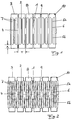
- the lamella strip shown in Fig. 1 consists of one - apart from bead-like embossing (see below) - flat sheet metal, in which by separating cuts 1, which face each other in pairs and which a distance from each other corresponding to the division T. have slats 2 are formed.
- the Separating cuts 1 each extend from the edge 3 into the metal strip. They end at a distance the opposite cut under training one each two adjacent slats with each other connecting web 4.
- the width of the web is about 15% of the width of the lamella strip.
- Each Slat 2 comprises two opposite one another Lamella legs 5a and 5b.
- each lamella 2 there is a parallel to the separating cuts 1 running middle cut 6 introduced. This extends over about 60 - 70% of the width of the Slat strips and ends at a distance from each Edges 3 of the slat strip. Furthermore points each lamella 2 has two bead-like embossments 7, the on both sides of the middle section 6 of the corresponding slat 2 are arranged.
- the bead-like embossments 7 extend parallel to the middle cuts 6 over essentially the same Length like or slightly longer than this. You end up thus with a distance A in front of the edges 3 of the Slat strip, so that each slat leg 5a or 5b a non-embossed, smooth end region 8 having.
- U-shaped cutouts 9 are provided in the area of the ends of the separating cuts 1 . Their depth corresponds to the width A of the non-embossed, smooth End regions 8 of the lamella legs. The width of the Excerpts amount to approximately 12% of the division T.
- the cutouts 9 are optionally rounded 10 in the corresponding edge 3 of the lamella strip about.
Landscapes
- Engineering & Computer Science (AREA)
- Mechanical Engineering (AREA)
- Shaping Metal By Deep-Drawing, Or The Like (AREA)
- Laminated Bodies (AREA)
- Bending Of Plates, Rods, And Pipes (AREA)
- Gasket Seals (AREA)
- Catalysts (AREA)
Priority Applications (1)
| Application Number | Priority Date | Filing Date | Title |
|---|---|---|---|
| DE29823835U DE29823835U1 (de) | 1997-06-13 | 1998-06-05 | Metallischer Lamellenstreifen sowie aus ihm hergestelltes Gerüstband |
Applications Claiming Priority (2)
| Application Number | Priority Date | Filing Date | Title |
|---|---|---|---|
| DE19725166A DE19725166A1 (de) | 1997-06-13 | 1997-06-13 | Metallischer Lamellenstreifen, Verfahren zu seiner Herstellung sowie aus im hergestelltes Gerüstband |
| DE19725166 | 1997-06-13 |
Publications (2)
| Publication Number | Publication Date |
|---|---|
| EP0884209A1 true EP0884209A1 (fr) | 1998-12-16 |
| EP0884209B1 EP0884209B1 (fr) | 2000-10-18 |
Family
ID=7832465
Family Applications (1)
| Application Number | Title | Priority Date | Filing Date |
|---|---|---|---|
| EP98110301A Expired - Lifetime EP0884209B1 (fr) | 1997-06-13 | 1998-06-05 | Bande à lamelles métalliques, son procédé de fabrication et armature préparée à partir de celui-ci |
Country Status (4)
| Country | Link |
|---|---|
| EP (1) | EP0884209B1 (fr) |
| AT (1) | ATE197022T1 (fr) |
| DE (2) | DE19725166A1 (fr) |
| ES (1) | ES2150807T3 (fr) |
Cited By (5)
| Publication number | Priority date | Publication date | Assignee | Title |
|---|---|---|---|---|
| US6306522B1 (en) | 1999-10-26 | 2001-10-23 | Geissler Stanztechnik Gmbh | Metal lamella strip, process for its production, as well as a framework band made from it |
| EP1666295A3 (fr) * | 2004-12-06 | 2007-09-05 | BFC Büro- und Fahrzeugtechnik GmbH & Co. Prod. KG | Lame métallique d'insertion pour bandes décorative et d'étanchéité |
| EP2401462A4 (fr) * | 2009-02-26 | 2013-01-23 | Henniges Automotive Sealing Systems North America Inc | Support de caoutchouc d'étanchéité renforcé mécaniquement |
| EP3924198A1 (fr) * | 2019-12-03 | 2021-12-22 | BFC Fahrzeugteile GmbH | Bande métallique |
| EP4096851B1 (fr) | 2020-01-28 | 2025-05-14 | BFC Fahrzeugteile GmbH | Ruban métallique utilisé comme armature pour bande de protection de bord et procédé de fabrication de ce ruban métallique |
Families Citing this family (2)
| Publication number | Priority date | Publication date | Assignee | Title |
|---|---|---|---|---|
| DE10101778C1 (de) * | 2001-01-17 | 2002-06-20 | Saar Gummiwerk Gmbh | Trägerband für Karosseriedichtungen |
| DE102015120415B4 (de) * | 2015-11-25 | 2022-12-29 | Cqlt Saargummi Technologies S.À.R.L. | Verstärkungsprofil |
Citations (9)
| Publication number | Priority date | Publication date | Assignee | Title |
|---|---|---|---|---|
| DE2717837A1 (de) | 1976-04-26 | 1977-11-03 | Draftex Dev Ag | U-foermiger profilstreifen |
| GB2052318A (en) * | 1979-05-31 | 1981-01-28 | Toyoda Gosei Kk | Method for producing a channel-shaped trim |
| JPS60215447A (ja) * | 1984-04-11 | 1985-10-28 | Toyoda Gosei Co Ltd | トリム芯金 |
| DE8607576U1 (de) | 1985-03-21 | 1986-08-21 | Silent Channel Products Ltd., Huntingdon, Cambridgeshire | Streifenprofil zum Aufklemmen auf einen Flansch |
| DE3708889A1 (de) | 1987-03-19 | 1988-09-29 | Happich Gmbh Gebr | Verfahren zur herstellung einer profilleiste aus gummi od. dgl. sowie profilleiste |
| FR2650648A1 (fr) | 1989-08-02 | 1991-02-08 | Mesnel Sa Ets | Procede de fabrication d'une armature metallique pour profiles en une matiere synthetique resiliente |
| EP0416433A2 (fr) | 1989-09-02 | 1991-03-13 | Draftex Industries Limited | Bande d'étancheité profilée |
| US5302466A (en) * | 1991-09-04 | 1994-04-12 | The Gem City Engineering Co. | Expanded metal strip for reinforcing a resilient product |
| EP0710788A1 (fr) * | 1994-11-07 | 1996-05-08 | Standard Products Industriel | Armature interne pour joints d'étanchéité |
-
1997
- 1997-06-13 DE DE19725166A patent/DE19725166A1/de not_active Withdrawn
-
1998
- 1998-06-05 DE DE59800303T patent/DE59800303D1/de not_active Expired - Fee Related
- 1998-06-05 EP EP98110301A patent/EP0884209B1/fr not_active Expired - Lifetime
- 1998-06-05 AT AT98110301T patent/ATE197022T1/de not_active IP Right Cessation
- 1998-06-05 ES ES98110301T patent/ES2150807T3/es not_active Expired - Lifetime
Patent Citations (9)
| Publication number | Priority date | Publication date | Assignee | Title |
|---|---|---|---|---|
| DE2717837A1 (de) | 1976-04-26 | 1977-11-03 | Draftex Dev Ag | U-foermiger profilstreifen |
| GB2052318A (en) * | 1979-05-31 | 1981-01-28 | Toyoda Gosei Kk | Method for producing a channel-shaped trim |
| JPS60215447A (ja) * | 1984-04-11 | 1985-10-28 | Toyoda Gosei Co Ltd | トリム芯金 |
| DE8607576U1 (de) | 1985-03-21 | 1986-08-21 | Silent Channel Products Ltd., Huntingdon, Cambridgeshire | Streifenprofil zum Aufklemmen auf einen Flansch |
| DE3708889A1 (de) | 1987-03-19 | 1988-09-29 | Happich Gmbh Gebr | Verfahren zur herstellung einer profilleiste aus gummi od. dgl. sowie profilleiste |
| FR2650648A1 (fr) | 1989-08-02 | 1991-02-08 | Mesnel Sa Ets | Procede de fabrication d'une armature metallique pour profiles en une matiere synthetique resiliente |
| EP0416433A2 (fr) | 1989-09-02 | 1991-03-13 | Draftex Industries Limited | Bande d'étancheité profilée |
| US5302466A (en) * | 1991-09-04 | 1994-04-12 | The Gem City Engineering Co. | Expanded metal strip for reinforcing a resilient product |
| EP0710788A1 (fr) * | 1994-11-07 | 1996-05-08 | Standard Products Industriel | Armature interne pour joints d'étanchéité |
Non-Patent Citations (1)
| Title |
|---|
| PATENT ABSTRACTS OF JAPAN vol. 10, no. 73 (M - 463)<2130> 22 March 1986 (1986-03-22) * |
Cited By (8)
| Publication number | Priority date | Publication date | Assignee | Title |
|---|---|---|---|---|
| US6306522B1 (en) | 1999-10-26 | 2001-10-23 | Geissler Stanztechnik Gmbh | Metal lamella strip, process for its production, as well as a framework band made from it |
| EP1666295A3 (fr) * | 2004-12-06 | 2007-09-05 | BFC Büro- und Fahrzeugtechnik GmbH & Co. Prod. KG | Lame métallique d'insertion pour bandes décorative et d'étanchéité |
| US7368175B2 (en) | 2004-12-06 | 2008-05-06 | Bfc Buro-Und Fahrzeugtechnik Gmbh & Co. Prod. Kg | Metal band as an inlay for trim strips or sealing strips |
| EP2401462A4 (fr) * | 2009-02-26 | 2013-01-23 | Henniges Automotive Sealing Systems North America Inc | Support de caoutchouc d'étanchéité renforcé mécaniquement |
| EP3924198A1 (fr) * | 2019-12-03 | 2021-12-22 | BFC Fahrzeugteile GmbH | Bande métallique |
| EP3924198B1 (fr) * | 2019-12-03 | 2025-12-31 | BFC Fahrzeugteile GmbH | Bande métallique |
| EP4671015A3 (fr) * | 2019-12-03 | 2026-03-04 | BFC Fahrzeugteile GmbH | Bande métallique |
| EP4096851B1 (fr) | 2020-01-28 | 2025-05-14 | BFC Fahrzeugteile GmbH | Ruban métallique utilisé comme armature pour bande de protection de bord et procédé de fabrication de ce ruban métallique |
Also Published As
| Publication number | Publication date |
|---|---|
| EP0884209B1 (fr) | 2000-10-18 |
| DE59800303D1 (de) | 2000-11-23 |
| DE19725166A1 (de) | 1998-12-17 |
| ATE197022T1 (de) | 2000-11-15 |
| ES2150807T3 (es) | 2000-12-01 |
Similar Documents
| Publication | Publication Date | Title |
|---|---|---|
| DE2937454C2 (de) | Verbundprofil, insbesondere für Fenster, Türen und Fassaden sowie Verfahren zum Herstellen des Verbundprofils | |
| DE69501998T2 (de) | Armierung für Dichtungsstreifen, Führungsleisten und Randleisten | |
| DE69808948T2 (de) | Stossfänger und herstellungsverfahren | |
| DE69207684T2 (de) | Dichtungsleiste mit expandierbarer Breite | |
| DE2926446C2 (de) | An einem Kantenbesatz vorgesehene oder als Kantenbesatz zu verwendende und einen Steg U-förmig umgreifende Klemmleiste | |
| DE3020447A1 (de) | Verfahren zum herstellen einer u-profil-zierleiste | |
| EP0282918B1 (fr) | Profilé en caoutchouc et procédé de fabrication | |
| DE2817716A1 (de) | U-foermiger dichtstreifen | |
| DE4231213C2 (de) | Verfahren zum Herstellen eines trägerartigen Formkörpers | |
| EP0884209B1 (fr) | Bande à lamelles métalliques, son procédé de fabrication et armature préparée à partir de celui-ci | |
| DE68902221T2 (de) | Verfahren und streifen zum herstellen einer u-foermigen fuehrung in einer nute eines fensterrahmens. | |
| DE19857589C2 (de) | Aufprallträger für Fahrzeugtüren und Verfahren zu seiner Herstellung | |
| EP0441287B1 (fr) | Lame métallique d'insertion pour bandes d'enjolivement et d'étanchéité | |
| DE19645517A1 (de) | Türblatt, insbesondere für Aufzugstüren | |
| WO2023217534A1 (fr) | Bande métallique et son procédé de production | |
| EP1464526B1 (fr) | Lame métallique d'insertion pour bandes d'enjolivement ou d'étanchéité | |
| DE3401096C2 (fr) | ||
| DE29823835U1 (de) | Metallischer Lamellenstreifen sowie aus ihm hergestelltes Gerüstband | |
| DE69611998T2 (de) | Stange eines gepäckträgers und verfahren zur herstellung | |
| DE4303435C2 (de) | Rammschutzträger für Türen und Seitenwände von Kraftfahrzeugkarosserien | |
| DE29620673U1 (de) | Metallisches Gerüstband | |
| DE69101580T2 (de) | Profilverstärkungskern, insbesondere zum Gebrauch in der Kraftfahrzeugindustrie. | |
| CH675614A5 (fr) | ||
| CH615976A5 (en) | Roller-shutter slat and method of manufacturing it | |
| DE69002226T2 (de) | Verfahren zum Herstellen einer metallischen Armatur für Profile in biegsamem synthetischem Material. |
Legal Events
| Date | Code | Title | Description |
|---|---|---|---|
| PUAI | Public reference made under article 153(3) epc to a published international application that has entered the european phase |
Free format text: ORIGINAL CODE: 0009012 |
|
| 17P | Request for examination filed |
Effective date: 19981020 |
|
| AK | Designated contracting states |
Kind code of ref document: A1 Designated state(s): AT DE ES FR GB IT SE |
|
| AX | Request for extension of the european patent |
Free format text: AL;LT;LV;MK;RO;SI |
|
| AKX | Designation fees paid |
Free format text: AT DE ES FR GB IT SE |
|
| RAP1 | Party data changed (applicant data changed or rights of an application transferred) |
Owner name: GEISSLER STANZTECHNIK GMBH |
|
| GRAG | Despatch of communication of intention to grant |
Free format text: ORIGINAL CODE: EPIDOS AGRA |
|
| GRAG | Despatch of communication of intention to grant |
Free format text: ORIGINAL CODE: EPIDOS AGRA |
|
| GRAH | Despatch of communication of intention to grant a patent |
Free format text: ORIGINAL CODE: EPIDOS IGRA |
|
| GRAG | Despatch of communication of intention to grant |
Free format text: ORIGINAL CODE: EPIDOS AGRA |
|
| 17Q | First examination report despatched |
Effective date: 20000412 |
|
| GRAH | Despatch of communication of intention to grant a patent |
Free format text: ORIGINAL CODE: EPIDOS IGRA |
|
| GRAA | (expected) grant |
Free format text: ORIGINAL CODE: 0009210 |
|
| AK | Designated contracting states |
Kind code of ref document: B1 Designated state(s): AT DE ES FR GB IT SE |
|
| REF | Corresponds to: |
Ref document number: 197022 Country of ref document: AT Date of ref document: 20001115 Kind code of ref document: T |
|
| ITF | It: translation for a ep patent filed | ||
| REF | Corresponds to: |
Ref document number: 59800303 Country of ref document: DE Date of ref document: 20001123 |
|
| ET | Fr: translation filed | ||
| REG | Reference to a national code |
Ref country code: ES Ref legal event code: FG2A Ref document number: 2150807 Country of ref document: ES Kind code of ref document: T3 |
|
| GBT | Gb: translation of ep patent filed (gb section 77(6)(a)/1977) |
Effective date: 20001214 |
|
| PG25 | Lapsed in a contracting state [announced via postgrant information from national office to epo] |
Ref country code: SE Free format text: LAPSE BECAUSE OF FAILURE TO SUBMIT A TRANSLATION OF THE DESCRIPTION OR TO PAY THE FEE WITHIN THE PRESCRIBED TIME-LIMIT Effective date: 20010118 |
|
| PG25 | Lapsed in a contracting state [announced via postgrant information from national office to epo] |
Ref country code: AT Free format text: LAPSE BECAUSE OF NON-PAYMENT OF DUE FEES Effective date: 20010605 |
|
| PLBE | No opposition filed within time limit |
Free format text: ORIGINAL CODE: 0009261 |
|
| STAA | Information on the status of an ep patent application or granted ep patent |
Free format text: STATUS: NO OPPOSITION FILED WITHIN TIME LIMIT |
|
| 26N | No opposition filed | ||
| REG | Reference to a national code |
Ref country code: GB Ref legal event code: IF02 |
|
| PGFP | Annual fee paid to national office [announced via postgrant information from national office to epo] |
Ref country code: ES Payment date: 20030623 Year of fee payment: 6 |
|
| PG25 | Lapsed in a contracting state [announced via postgrant information from national office to epo] |
Ref country code: ES Free format text: LAPSE BECAUSE OF NON-PAYMENT OF DUE FEES Effective date: 20040607 |
|
| PGFP | Annual fee paid to national office [announced via postgrant information from national office to epo] |
Ref country code: FR Payment date: 20040618 Year of fee payment: 7 |
|
| PGFP | Annual fee paid to national office [announced via postgrant information from national office to epo] |
Ref country code: GB Payment date: 20040629 Year of fee payment: 7 |
|
| PGFP | Annual fee paid to national office [announced via postgrant information from national office to epo] |
Ref country code: DE Payment date: 20040827 Year of fee payment: 7 |
|
| PG25 | Lapsed in a contracting state [announced via postgrant information from national office to epo] |
Ref country code: IT Free format text: LAPSE BECAUSE OF NON-PAYMENT OF DUE FEES Effective date: 20050605 Ref country code: GB Free format text: LAPSE BECAUSE OF NON-PAYMENT OF DUE FEES Effective date: 20050605 |
|
| REG | Reference to a national code |
Ref country code: ES Ref legal event code: FD2A Effective date: 20040607 |
|
| PG25 | Lapsed in a contracting state [announced via postgrant information from national office to epo] |
Ref country code: DE Free format text: LAPSE BECAUSE OF NON-PAYMENT OF DUE FEES Effective date: 20060103 |
|
| PG25 | Lapsed in a contracting state [announced via postgrant information from national office to epo] |
Ref country code: FR Free format text: LAPSE BECAUSE OF NON-PAYMENT OF DUE FEES Effective date: 20060228 |
|
| GBPC | Gb: european patent ceased through non-payment of renewal fee |
Effective date: 20050605 |
|
| REG | Reference to a national code |
Ref country code: FR Ref legal event code: ST Effective date: 20060228 |