EP4096851B1 - Ruban métallique utilisé comme armature pour bande de protection de bord et procédé de fabrication de ce ruban métallique - Google Patents
Ruban métallique utilisé comme armature pour bande de protection de bord et procédé de fabrication de ce ruban métallique Download PDFInfo
- Publication number
- EP4096851B1 EP4096851B1 EP21703622.7A EP21703622A EP4096851B1 EP 4096851 B1 EP4096851 B1 EP 4096851B1 EP 21703622 A EP21703622 A EP 21703622A EP 4096851 B1 EP4096851 B1 EP 4096851B1
- Authority
- EP
- European Patent Office
- Prior art keywords
- band
- impressions
- metal
- strip
- flat side
- Prior art date
- Legal status (The legal status is an assumption and is not a legal conclusion. Google has not performed a legal analysis and makes no representation as to the accuracy of the status listed.)
- Active
Links
Images



Classifications
-
- B—PERFORMING OPERATIONS; TRANSPORTING
- B21—MECHANICAL METAL-WORKING WITHOUT ESSENTIALLY REMOVING MATERIAL; PUNCHING METAL
- B21H—MAKING PARTICULAR METAL OBJECTS BY ROLLING, e.g. SCREWS, WHEELS, RINGS, BARRELS, BALLS
- B21H8/00—Rolling metal of indefinite length in repetitive shapes specially designed for the manufacture of particular objects, e.g. checkered sheets
-
- B—PERFORMING OPERATIONS; TRANSPORTING
- B60—VEHICLES IN GENERAL
- B60R—VEHICLES, VEHICLE FITTINGS, OR VEHICLE PARTS, NOT OTHERWISE PROVIDED FOR
- B60R13/00—Elements for body-finishing, identifying, or decorating; Arrangements or adaptations for advertising purposes
- B60R13/04—External Ornamental or guard strips; Ornamental inscriptive devices thereon
-
- B—PERFORMING OPERATIONS; TRANSPORTING
- B21—MECHANICAL METAL-WORKING WITHOUT ESSENTIALLY REMOVING MATERIAL; PUNCHING METAL
- B21D—WORKING OR PROCESSING OF SHEET METAL OR METAL TUBES, RODS OR PROFILES WITHOUT ESSENTIALLY REMOVING MATERIAL; PUNCHING METAL
- B21D28/00—Shaping by press-cutting; Perforating
- B21D28/24—Perforating, i.e. punching holes
- B21D28/243—Perforating, i.e. punching holes in profiles
-
- B—PERFORMING OPERATIONS; TRANSPORTING
- B21—MECHANICAL METAL-WORKING WITHOUT ESSENTIALLY REMOVING MATERIAL; PUNCHING METAL
- B21D—WORKING OR PROCESSING OF SHEET METAL OR METAL TUBES, RODS OR PROFILES WITHOUT ESSENTIALLY REMOVING MATERIAL; PUNCHING METAL
- B21D31/00—Other methods for working sheet metal, metal tubes, metal profiles
- B21D31/04—Expanding other than provided for in groups B21D1/00 - B21D28/00, e.g. for making expanded metal
-
- B—PERFORMING OPERATIONS; TRANSPORTING
- B60—VEHICLES IN GENERAL
- B60J—WINDOWS, WINDSCREENS, NON-FIXED ROOFS, DOORS, OR SIMILAR DEVICES FOR VEHICLES; REMOVABLE EXTERNAL PROTECTIVE COVERINGS SPECIALLY ADAPTED FOR VEHICLES
- B60J10/00—Sealing arrangements
- B60J10/15—Sealing arrangements characterised by the material
- B60J10/18—Sealing arrangements characterised by the material provided with reinforcements or inserts
Definitions
- the present invention relates to a metal strip as an insert for decorative, sealing or edge protection strips, in particular for motor vehicles.
- a metal strip having the features of the preamble of claim 1 is known from JP 2011 143918 A
- metal strips are also used as inserts for edge protection strips from DE 10 2018 004379 A1 , US 2004/150171 A1 and the DE 30 20 447 A1 known.
- Such metal strips are used particularly in the automotive sector as inserts for sealing strips for sealing engine compartments, trunks, and door and window openings.
- the continuously manufactured metal strips are coated with a sealing material, such as rubber and/or flexible plastic, and often have slits, among other things to allow the sealing material to penetrate non-adhesive-coated metal strips, since adhesion between rubber and metal or between plastic and metal is not possible or insufficient.
- adhesive-coated metal strips are very expensive.
- slits which can be produced particularly by rotary cutting, such metal strips can also have punched openings. Cut slits can be widened by rolling.
- metal strips without openings can also be used, especially if the finished sealing strips have large radii of curvature when installed. These generally require an adhesive coating.
- the clamping profile should be flexible in both directions perpendicular to its longitudinal direction. Furthermore, the clamping profile should be compressible in its longitudinal direction if the openings to be sealed have circumferential tolerances, as cutting the sealing strip to length on site would be very complex.
- the clamping profile must also exhibit a certain tensile strength and rigidity, since decorative, sealing, or edge protection strips are usually manufactured by extrusion, which involves considerable forces in the longitudinal direction of the strip. Another requirement of the clamping profile is to exert the greatest possible clamping force on the sealing flanges.
- the interdental spaces which can have an opening width of 0.5 to 1.5 mm or more, result in an undesirable "hungry horse” effect on the finished profile, i.e., a very unsightly, rough, or wavy surface, which can be concealed with various measures, such as flocking, covering with textiles, covering with additional lips, decorative strips, or applying various knurling.
- measures such as flocking, covering with textiles, covering with additional lips, decorative strips, or applying various knurling.
- the invention is based on the object of avoiding the aforementioned disadvantages.
- it is intended to provide a metal strip that does not require a coating and yet still allows for good adhesion between the plastic or rubber on the one hand and the metal strip on the other.
- a metal strip having the features of claim 1 or by a decorative, sealing, or edge protection strip having the features of claim 12.
- the object is achieved in that the surface is profiled on at least one flat side of the strip.
- Profiling at least one flat side of the metal strip increases the surface area of the strip. This can improve the adhesion between the plastic or rubber and the metal strip. In addition, the profiled structure of the respective surface also leads to a better adhesive bond between plastic or rubber on the one hand and metal strip on the other.
- the metal strip according to the invention is significantly more cost-effective than known strips, especially coated strips. Furthermore, strips according to the invention are easier to manufacture, making them readily available. Finally, the profiling can also result in partial material hardening, thus increasing the strength of the strip.
- the strip has a plurality of successive, particularly slot-like, perforations in the longitudinal direction of the strip.
- the perforations in the strip allow for greater flexibility of the metal strip, allowing the metal strip or the decorative, sealing, or edge protection strip made from it to adapt better to the edge of the opening.
- the surface profiling is formed according to the invention on at least one flat side of the strip by a surface-enlarging grid pattern consisting of a plurality of impressions. Due to the enlarged surface, the metal strip has a larger contact area for the sealing material, allowing it to bond more firmly to the metal strip.
- Surface enlargement means that the surface of the metal strip profiled by means of a large number of embossed indentations has a larger surface area than the unprofiled surface of the metal strip.
- the surface enlargement is achieved by stretching the sheet material through cold forming to create the indentations, which ultimately increases the surface area of the embossed metal strip compared to the unembossed metal strip.
- the metal strip can preferably be provided with a plurality of impressions.
- the surface of the respective flat side of the metal strip can be provided with a profile in certain areas or completely.
- the surface can be provided with a profile in one or more longitudinal strips.
- the profile can be provided in areas with perforations or in areas without perforations. Providing a profile in areas without perforations has the advantage that, where no plastic or rubber material can penetrate the metal strip, good adhesion can still be achieved between the plastic or rubber on the one hand and the metal strip on the other.
- the surface profiling on the respective flat side of the metal strip can preferably have a repeating pattern in the longitudinal and/or transverse direction of the strip. This ensures consistently good adhesion across the strip, and it also makes such a pattern easy to manufacture.
- the adhesion between the metal strip and the sealing material is preferably achieved by a multitude of closely spaced individual embossings.
- the profiling can have a density of up to 700, preferably up to 800, and particularly preferably up to 850 embossings per square centimeter.
- the surface of the metal strip has a profiling with up to 700 embossings per square centimeter, preferably up to 800 embossings per square centimeter, and particularly preferably up to 850 embossings per square centimeter.
- the embossing depth of the indentations can be continuously adjusted from 0.01 mm to 0.7 mm, so that the indentations can have an embossing depth of 0.01 mm to 0.7 mm.
- the embossing depth can be continuously adjusted, for example, by the contact pressure of a tool used for embossing, such as an embossing die or an embossing roller. The higher the contact pressure, the greater the embossing depth. The resulting surface elevation caused by the indentations is greater the greater the embossing depth, particularly since a greater embossing depth stretches the material of the metal strip more.
- At least one indentation can have a longitudinal extension, wherein the longitudinal extension of the indentations is oriented at an angle of 0° to 90° to the longitudinal direction of the strip.
- At least one indentation can be designed as a quasi-point-shaped pattern.
- a quasi-point-shaped pattern of the indentations allows for the creation of as many indentations as possible per unit area.
- the indentations have the shape of a three- or four-sided pyramid or truncated pyramid, the shape of a cone or truncated cone, the shape of a dome, a cylinder, a hipped roof, or a lens. Combinations of these shapes are also possible. Free-form indentations are also possible. This advantageously improves the anchoring of the rubber or plastic to the metal strip, eliminating the need for a coating of the metal strip.
- impressions can be arranged in successive rows and columns.
- the rows of impressions can extend in the longitudinal direction, i.e., parallel to the longitudinal direction of the strip, and the columns in the transverse direction, i.e., parallel to the transverse direction of the strip.
- This allows the surface of the metal strip to be produced in a roll-embossing process using an embossing roller aligned transversely, in particular at right angles, to the longitudinal direction of the strip.
- the rows of impressions can be aligned obliquely, i.e., at an angle deviating from 0°, such as 45°, with respect to the longitudinal direction of the strip.
- the columns of impressions can be aligned obliquely, i.e., at an angle deviating from 0°, such as 45°, with respect to the transverse direction of the strip.
- the indentations of consecutive columns of indentations in the longitudinal direction of the strip can be offset from one another in the transverse direction.
- the densest possible arrangement of the indentations can preferably be achieved by offsetting the indentations of consecutive columns of indentations in the longitudinal direction of the strip by half the longitudinal extent of an indentation.
- the distance between the centers of an indentation and an immediately adjacent indentation, viewed in the transverse direction of the strip is less than 1.0 mm, preferably less than 0.7 mm, and particularly preferably less than 0.4 mm. Additionally or alternatively, the distance between the centers of an indentation and an immediately adjacent indentation, viewed in the longitudinal direction of the strip, can be less than 0.7 mm, preferably less than 0.5 mm, and particularly preferably less than 0.3 mm. Such small distances between adjacent indentations allow for the creation of as many surface-enhancing indentations as possible per unit area.
- Particularly high adhesion of the sealing material can be achieved by embossing both flat sides of the strip.
- only one flat side of the strip can be embossed, which makes the metal strip particularly easy and cost-effective to manufacture.
- double-sided profiling of the strip surface can be achieved by profiling each flat side of the strip using an embossing roller.
- the metal strip is passed between two embossing rollers.
- one flat side is provided with indentations in such a way that no indentation is produced on the opposite flat side.
- the metal band is preferably made of steel, especially stainless steel, or aluminum. This material has proven advantageous for the aforementioned applications.
- a metal strip thickness between 0.25 mm and 1 mm has also proven advantageous for the aforementioned applications.
- a material thickness range of 0.4 mm to 0.8 mm is particularly preferred.
- the invention also relates to a decorative, sealing or edge protection strip with a metal strip of the type described above, wherein a sealing material surrounding the strip at least in regions is applied in an intimately connected manner to the surface of the strip at least in the region of the profiling.
- the metal strip of the type described above is preferably used as an insert in a decorative, sealing or edge protection strip.
- Profiling the surface of the flat side can be performed both before and after the perforations are created. However, particularly good profiling is achieved when the strip surface is profiled after the perforations are created, as the shape and embossing depth are then not affected by the creation of the perforations, especially by the lengthening of the metal sheet.
- the surface of the flat side can be profiled in a roll-embossing process using at least one embossing roller.
- a peripheral surface of the embossing roller can have a shape complementary to the shape of the impressions to be embossed.
- the metal strip 1 shown has no slits or perforations. As can be seen particularly in Fig. 2 However, as can be seen, the surface of the illustrated flat side 4 of the metal strip 1 is profiled. In particular, the flat side 4 is provided with a plurality of indentations 5 that are evenly distributed over the entire surface of this flat side 4. The flat side 4 is provided with indentations 5 in such a way that no indentation results on the opposite flat side 4.
- both flat sides 4 of the band 1 have indentations.
- a profiling in the form of a surface-enlarging grid pattern consisting of a plurality of indentations 5 is formed on the correspondingly profiled flat side 4 of the strip 1.
- the profiling can have a density of up to 700, preferably up to 800, and particularly preferably up to 850 indentations 5 on an area of one square centimeter. In the illustrated embodiment, 833 indentations per square centimeter are provided.
- the impression 5 can have an embossing depth of 0.01 mm to 0.7 mm.
- the indentations 5 have a longitudinal extension.
- the longitudinal extension of the indentations 5 is aligned at an angle of at least approximately 90° with respect to the longitudinal direction I of the strip 1, or in other words, the longitudinal extension of the indentations 5 is aligned at least approximately parallel to the transverse direction II of the strip 1.
- the indentations 5 can also be aligned with their respective longitudinal extension at an angle other than 90° to the longitudinal direction I of the strip 1.
- Fig. 2 to 6 As can be seen, several impressions 5 are arranged in successive rows and columns, wherein the rows extend in the longitudinal direction I of the strip 1 and the columns in the transverse direction II of the strip 1.
- the several impressions 5 are each arranged one behind the other in a column in the longitudinal direction I of the strip 1, wherein the columns of the impressions 5 correspond to the longitudinal extent of the impressions 5 transverse to the Longitudinal direction I of the strip 1.
- the columns of consecutively arranged impressions 5 are aligned at least approximately parallel to the transverse direction II of the strip 1.
- the indentations 5 of consecutive columns of indentations 5 in the longitudinal direction I of the strip 1 are offset from one another in the transverse direction II. More precisely, the indentations 5 of consecutive columns of indentations 5 in the longitudinal direction of the strip are offset from one another by half the longitudinal extent of an indentation 5.
- the indentations 5 form a pattern that repeats in both the longitudinal direction I and the transverse direction II of the metal strip 1.
- the distance between the centers of an indentation 5 and an immediately adjacent indentation 5 in the transverse direction II of the strip 1 can be less than 1.0 mm and preferably less than 0.7 mm. In the exemplary embodiments, the distance between two indentations 5 in the transverse direction II of the strip 1 is less than 0.4 mm.
- the distance between the centers of an indentation 5 and an immediately adjacent indentation 5, viewed in the longitudinal direction I of the strip 1, can be less than 0.7 mm and preferably less than 0.5 mm.
- the distance between two adjacent indentations 5, viewed in the longitudinal direction I of the strip 1, is less than 0.3 mm. Since the columns of indentations 5 follow one another in the longitudinal directions, the distance between two columns of indentations 5 is consequently also less than 0.3 mm.
- the second flat side of the metal strip 1 can be profiled or smooth in a corresponding manner. This ensures good adhesion between the metal strip and the plastic coating, even without an adhesive coating and without perforations.
- the indentations 5 may also have no longitudinal extension, but may be configured as point-like elements.
- the indentations 5 may have the shape of a three- or four-sided pyramid or truncated pyramid, a cone or truncated cone, a dome, a cylinder, a hipped roof, a lens, transverse grooves or longitudinal grooves, as well as a free form, or combinations thereof.
- the metal strip is preferably made of stainless steel or aluminum and has a material thickness between 0.25 mm and 1 mm. The material thickness is preferably 0.4 to 0.8 mm.
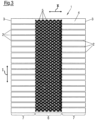
- Fig. 3 In principle, this corresponds to the embodiment of the Fig. 1 and 2 In contrast to the example of the Fig. 1 and 2 However, the indentations 5 are only present in a central region 6 viewed across the transverse direction II of the metal strip 1. In this central region 6, the metal strip 1 has no perforations.
- the strip 1 has a plurality of slit-like perforations 2 that follow one another in the longitudinal direction I of the strip 1. As already mentioned, there are no indentations 5 in these two edge regions 7, so the surface of the metal strip 1 is not profiled in these regions.
- Fig. 4 largely agrees with the example of Fig. 3 In contrast to the example of Fig. 3 However, here the indentations 5 are provided exclusively in the two edge areas 7, while in the central area 6 there is no profiling of the surface of the metal strip 1.
- the metal band of the embodiment of Fig. 5 are next to the openings 2, which are designed as slots leading inwards from the two edges 3 are designed, there are also island perforations 8 in the central region 6 of the metal strip.
- the island perforations 8, like the edge slots 2, are provided successively in the longitudinal direction I of the strip, with three tracks of island perforations 8 being present which overlap one another.
- the entire surface of the flat side 4 of the metal strip 1 shown is profiled by indentations 5 being introduced into this flat side 4.
- the opposite flat side of the metal strip can also be provided with such or other indentations as a profiling.
- Fig. 6 shows an embodiment of the metal strip 1 according to the invention with an asymmetrical design.
- Perforations 2 are provided only in an area 9, which extends from one edge 3 of the metal strip to almost its center.
- the remaining area 10 of the metal strip which extends from the other edge 3 of the metal strip to the first area 9, there are no perforations.
- the second area 10 is provided with a profiled surface in that indentations 5 are present in the flat side 4 shown, while no profiling is provided in the first area 9.
- the profiling is designed as a repeating pattern and can also be present on the opposite flat side of the metal strip in this or a different form.
- All metal strips shown are preferably made of steel, in particular stainless steel, or aluminum, and have a material thickness of preferably between 0.25 mm and 1 mm, in particular between 0.4 mm and 0.8 mm.
- the indentations 5 of the metal strips shown can each have the shape corresponding to the embodiment of Fig. 1 was described. Contrary to what is shown, the impressions 5 may not follow a pattern, but may be randomly distributed over the surface of the respective flat side 4. Likewise, the distribution of the profiling across different areas of the metal strip 1 may be selected differently.
- the metal strip according to the invention is characterized by good adhesion properties to plastic or rubber. It can therefore be used without a surface coating for decorative, sealing, or edge protection strips, particularly for motor vehicles.
- the metal strips shown are preferably bent into a U-shaped profile, each forming a clamping profile.
- a method for producing a metal strip begins with the provision of a strip-like metal sheet. Successive openings 2, 8 are then created in the metal strip, for example by punching and/or cutting the metal sheet.
- the metal sheet can be pulled apart if necessary in order to enlarge the opening width of at least some of the openings 2, 8 by stretching the metal sheet.
- the surface of the flat side 4 or both surfaces of the flat side 4 are profiled, namely embossed, in order to produce a plurality of impressions 5.
- the profiling of the surface of the flat side 4 or the surfaces of the flat sides 4 can also take place before the openings 2, 8 are created.
- the profiling of the surface of the or each flat side 4 is carried out in a roll-embossing process using at least one embossing roller.
- the embossing roller has a peripheral surface that has a shape complementary to the shape of the impressions 5 to be embossed.
- the metal strip is then at least partially surrounded by a sealing material, such as a rubber or flexible plastic material, in order to form a decorative, sealing or edge protection strip with a metal strip inserted therein, in which the sealing material surrounds the strip 1 at least partially and in which the sealing material is applied in the area of the profiling in an intimately connected manner to the surface of the strip.
- a sealing material such as a rubber or flexible plastic material
Landscapes
- Engineering & Computer Science (AREA)
- Mechanical Engineering (AREA)
- Seal Device For Vehicle (AREA)
- Shaping Of Tube Ends By Bending Or Straightening (AREA)
- Laminated Bodies (AREA)
Claims (15)
- Ruban métallique à titre d'insert pour des bandes d'enjolivement, d'étanchéité ou de protection des bords, en particulier pour des véhicules automobiles, la surface étant profilée sur au moins une face plate (4) du ruban,
caractérisé en ce que
le profilage de la surface sur au moins une face plate (4) du ruban (1) est formé par un motif de trame agrandissant la surface et constitué d'une pluralité d'empreintes (5) qui sont réalisées de telle sorte qu'il n'en résulte pas de bosse respective sur la face plate opposée (4). - Ruban métallique selon la revendication 1,
caractérisé en ce que
le ruban (1) présente une pluralité d'ajours (2, 8), en particulier en forme de fentes, qui se succèdent dans la direction longitudinale (I) du ruban (1). - Ruban métallique selon l'une des revendications précédentes,
caractérisé en ce que
la surface de la face plate (4) n'est pourvue du profilage que localement, en particulier dans une ou plusieurs lames longitudinales (6, 7, 10). - Ruban métallique selon la revendication 2,
caractérisé en ce que
le profilage n'est prévu que dans des zones (7) avec des ajours (2), ou en ce que le profilage n'est prévu que dans des zones (6, 10) sans ajours (2). - Ruban métallique selon l'une des revendications précédentes 1 à 3,
caractérisé en ce que
la totalité de la surface de la face plate (4) est profilée. - Ruban métallique selon l'une des revendications précédentes,
caractérisé en ce quele profilage (5) présente un motif se répétant dans la direction longitudinale (I) et/ou dans la direction transversale (II) du ruban (1), et/ouen ce que le profilage présente une densité allant jusqu'à 700, de préférence jusqu'à 800 et de manière particulièrement préférée jusqu'à 850 empreintes (5) sur une surface d'un centimètre carré. - Ruban métallique selon l'une des revendications précédentes,
caractérisé en ce queles empreintes (5) présentent une profondeur d'estampage de 0,01 mm à 0,7 mm, et/ouen ce que les empreintes (5) ont une extension longitudinale, l'extension longitudinale des empreintes (5) étant orientée selon un angle de 0° à 90° par rapport à la direction longitudinale (I) du ruban (1), ouen ce que les empreintes (5) ont une forme quasi ponctuelle, en particulier, les empreintes (5) ayant la forme d'une pyramide ou d'une pyramide tronquée à trois ou quatre côtés, d'un cône ou d'un cône tronqué, d'une coupole, d'un cylindre, d'un toit en croupe, d'une lentille ou d'une forme libre. - Ruban métallique selon l'une des revendications précédentes,
caractérisé en ce que
plusieurs empreintes (5) sont disposées en rangées et en colonnes successives, en particulier, les rangées s'étendent dans la direction longitudinale (I) du ruban (1) et les colonnes s'étendent dans la direction transversale (II) du ruban (1), de manière particulièrement préférée, les empreintes (5) de colonnes d'empreintes (5) se succédant dans la direction longitudinale (I) du ruban (1) sont décalées les unes par rapport aux autres dans la direction transversale (II), en particulier de la moitié de l'extension longitudinale d'une empreinte (5). - Ruban métallique selon l'une des revendications 2 à 8,
caractérisé en ce quela distance entre les centres d'une empreinte (5) et d'une empreinte (5) immédiatement voisine, vue dans la direction transversale (II) du ruban (1), est inférieure à 1,0 mm, de préférence inférieure à 0,7 mm et de manière particulièrement préférée inférieure à 0,4 mm,
et/oula distance entre les centres d'une empreinte (5) et d'une empreinte (5) immédiatement voisine, vue dans la direction longitudinale (I) du ruban (1), est inférieure à 0,7 mm, de préférence inférieure à 0,5 mm et de manière particulièrement préférée inférieure à 0,3 mm. - Ruban métallique selon l'une des revendications précédentes,
caractérisé en ce que
les deux faces plates (4) du ruban (1) présentent des empreintes (5). - Ruban métallique selon l'une des revendications précédentes,
caractérisé en ce quele ruban métallique (1) est en acier, en particulier en acier inoxydable, ou en aluminium, et/ouen ce que le ruban métallique (1) présente une épaisseur de matériau de 0,25 mm à 1 mm, en particulier de 0,4 mm à 0,8 mm. - Bande d'enjolivement, d'étanchéité ou de protection des bords comprenant un ruban métallique selon l'une au moins des revendications 1 à 11, dans laquelle un matériau d'étanchéité entourant le ruban (1) au moins localement est appliqué en liaison intime avec la surface du ruban au moins dans la zone du profilage.
- Utilisation d'un ruban métallique selon l'une au moins des revendications 1 à 11 à titre d'insert dans une bande d'enjolivement, d'étanchéité ou de protection des bords.
- Procédé de fabrication d'un ruban métallique selon l'une au moins des revendications 1 à 11, ledit procédé comprenant les étapes suivantes consistant à :- fournir une tôle métallique de type ruban,- estamper la surface d'au moins une face plate (4) de la tôle métallique, en particulier pour produire une pluralité d'empreintes (5) qui sont réalisées de telle sorte qu'il n'en résulte pas de bosse respective sur la face plate opposée (4), et- de préférence, produire des ajours successifs (2, 8), en particulier par poinçonnage et/ou par découpe de la tôle métallique,- le cas échéant, de préférence, allonger la tôle métallique afin d'augmenter la largeur d'ouverture d'au moins une partie des ajours (2, 8) par allongement de la tôle métallique.
- Procédé selon la revendication 14,
caractérisé en ce quele profilage de la surface de la face plate (4) s'effectue avant ou après la production des ajours (2, 8), et/ouen ce que la surface de la face plate (4) est profilée dans un procédé d'estampage au rouleau au moyen d'au moins un cylindre d'estampage, en particulier une surface enveloppe du cylindre d'estampage présentant une forme conçue de manière complémentaire à la forme des empreintes (5) à estamper.
Applications Claiming Priority (2)
| Application Number | Priority Date | Filing Date | Title |
|---|---|---|---|
| DE102020101975.0A DE102020101975A1 (de) | 2020-01-28 | 2020-01-28 | Metallband |
| PCT/EP2021/051889 WO2021151962A1 (fr) | 2020-01-28 | 2021-01-27 | Ruban métallique utilisé comme armature pour bande de protection de bord et procédé de fabrication de ce ruban métallique |
Publications (3)
| Publication Number | Publication Date |
|---|---|
| EP4096851A1 EP4096851A1 (fr) | 2022-12-07 |
| EP4096851B1 true EP4096851B1 (fr) | 2025-05-14 |
| EP4096851C0 EP4096851C0 (fr) | 2025-05-14 |
Family
ID=74556870
Family Applications (1)
| Application Number | Title | Priority Date | Filing Date |
|---|---|---|---|
| EP21703622.7A Active EP4096851B1 (fr) | 2020-01-28 | 2021-01-27 | Ruban métallique utilisé comme armature pour bande de protection de bord et procédé de fabrication de ce ruban métallique |
Country Status (5)
| Country | Link |
|---|---|
| US (1) | US12330568B2 (fr) |
| EP (1) | EP4096851B1 (fr) |
| CN (1) | CN115023304A (fr) |
| DE (1) | DE102020101975A1 (fr) |
| WO (1) | WO2021151962A1 (fr) |
Families Citing this family (4)
| Publication number | Priority date | Publication date | Assignee | Title |
|---|---|---|---|---|
| DE102019115174A1 (de) * | 2019-06-05 | 2020-12-10 | Lübbers Anlagen- und Umwelttechnik GmbH | Verfahren zum Herstellen eines Lochbleches, Lochblech, Formteil und Aufbereitungsvorrichtung |
| DE102020101975A1 (de) | 2020-01-28 | 2021-07-29 | Bfc Fahrzeugteile Gmbh | Metallband |
| DE202021104735U1 (de) * | 2021-09-02 | 2021-10-04 | Bfc Fahrzeugteile Gmbh | Metallband |
| DE202022100637U1 (de) | 2022-02-03 | 2023-05-05 | STG Stanztechnik GmbH & Co. KG | Verstärkungsband für einen Formkörper aus einer spritzfähigen Formmasse sowie Formkörper mit einem derartigen Verstärkungsband |
Citations (10)
| Publication number | Priority date | Publication date | Assignee | Title |
|---|---|---|---|---|
| DE7802203U1 (de) | 1977-04-25 | 1978-08-17 | The Standard Products Co., Dearborn, Mich. (V.St.A.) | Zierleiste |
| EP0884209A1 (fr) | 1997-06-13 | 1998-12-16 | O & K Geissler Gmbh | Bande à lamelles métalliques, son procédé de fabrication et armature préparée à partir de celui-ci |
| DE10124484C1 (de) | 2001-05-19 | 2002-11-07 | Saar Gummiwerk Gmbh | Verfahren und Vorrichtung zum Einbringen eines in Längsrichtung wechselnden Schnitt- bzw. Stanzbildes in ein metallisches Trägerband für Karosseriedichtungen, sowie danach hergestellte Trägerbänder für Karosseriedichtungen |
| CN1181939C (zh) | 1998-03-24 | 2004-12-29 | 亨特道格拉斯国际有限公司 | 滚花带材 |
| US6964799B1 (en) | 1999-10-06 | 2005-11-15 | Nippon Ply Co., Ltd. | Shrinkage control material and elastomeric molding |
| CN103192228A (zh) | 2013-04-03 | 2013-07-10 | 昆山通塑机械制造有限公司 | 钢带滚花装置 |
| EP1693237B1 (fr) | 2005-02-22 | 2013-09-25 | BFC Fahrzeugteile GmbH | Lame métallique d'insertion pour bandes d'enjolivement et d'étanchéité |
| WO2016083026A1 (fr) | 2014-11-28 | 2016-06-02 | Sms Group Gmbh | Structuration de surface d'outils de formage |
| US20180154414A1 (en) | 2016-12-07 | 2018-06-07 | Kasei Kogyo, Co., Ltd. | Helical layer structure and manufacturing method of helical layer structure |
| WO2021151962A1 (fr) | 2020-01-28 | 2021-08-05 | Bfc Fahrzeugteile Gmbh | Ruban métallique utilisé comme armature pour bande de protection de bord et procédé de fabrication de ce ruban métallique |
Family Cites Families (16)
| Publication number | Priority date | Publication date | Assignee | Title |
|---|---|---|---|---|
| DE1248397B (de) | 1966-06-15 | 1967-08-24 | Goetzewerke | Flanschdichtung |
| JPS5936865B2 (ja) | 1979-05-31 | 1984-09-06 | 豊田合成株式会社 | トリムの製造方法 |
| DE4105367A1 (de) | 1991-02-21 | 1992-09-03 | Kempchen & Co Gmbh | Dichtungsband aus einem laengslaufenden blechstreifen und einer beidseitigen abdeckungsschicht |
| JP3080297B2 (ja) * | 1996-04-19 | 2000-08-21 | 片山特殊工業株式会社 | 金属シートの製造方法および該方法により製造された金属シート |
| DE29620673U1 (de) | 1996-11-19 | 1998-03-26 | O. & K. Geissler GmbH, 82131 Gauting | Metallisches Gerüstband |
| JP3405103B2 (ja) * | 1997-01-24 | 2003-05-12 | 日立電線株式会社 | 内面溝付管およびその製造方法 |
| US6889985B2 (en) | 2003-01-31 | 2005-05-10 | Scovil Hanna Corporation | Core metal insert for weatherseals |
| JP5042871B2 (ja) * | 2008-01-30 | 2012-10-03 | 日立電線株式会社 | 金属箔材の製造方法 |
| US8205390B2 (en) | 2009-02-26 | 2012-06-26 | Henniges Automotive Sealing Systems North America, Inc. | Mechanically stiffened weatherseal carrier |
| JP5563316B2 (ja) | 2009-03-18 | 2014-07-30 | 東海興業株式会社 | 芯材の製造方法及びトリム材の製造方法並びに芯材 |
| JP2011143918A (ja) * | 2009-12-18 | 2011-07-28 | Nishikawa Rubber Co Ltd | ウエザーストリップ用芯金 |
| KR101307866B1 (ko) | 2013-04-25 | 2013-09-12 | 임계화 | 차량의 웨더 스트립, 차량의 웨더 스트립용 보강재 및 그 제조방법 |
| WO2015139996A1 (fr) * | 2014-03-17 | 2015-09-24 | Acp Deutschland Gmbh & Co. Kg | Support métallique estampé pour des joints d'étanchéité |
| DE102015120415B4 (de) | 2015-11-25 | 2022-12-29 | Cqlt Saargummi Technologies S.À.R.L. | Verstärkungsprofil |
| DE102016005074A1 (de) * | 2016-04-27 | 2017-11-02 | Lwb Steinl Gmbh & Co. Kg | Gerüstband mit Verstärkungsmittel |
| DE102018004379A1 (de) | 2018-06-01 | 2019-12-05 | Psa Automobiles Sa | Einleger für eine Kraftfahrzeugdichtung und Kraftfahrzeugdichtung |
-
2020
- 2020-01-28 DE DE102020101975.0A patent/DE102020101975A1/de active Pending
-
2021
- 2021-01-27 CN CN202180011324.3A patent/CN115023304A/zh active Pending
- 2021-01-27 EP EP21703622.7A patent/EP4096851B1/fr active Active
- 2021-01-27 US US17/795,774 patent/US12330568B2/en active Active
- 2021-01-27 WO PCT/EP2021/051889 patent/WO2021151962A1/fr not_active Ceased
Patent Citations (10)
| Publication number | Priority date | Publication date | Assignee | Title |
|---|---|---|---|---|
| DE7802203U1 (de) | 1977-04-25 | 1978-08-17 | The Standard Products Co., Dearborn, Mich. (V.St.A.) | Zierleiste |
| EP0884209A1 (fr) | 1997-06-13 | 1998-12-16 | O & K Geissler Gmbh | Bande à lamelles métalliques, son procédé de fabrication et armature préparée à partir de celui-ci |
| CN1181939C (zh) | 1998-03-24 | 2004-12-29 | 亨特道格拉斯国际有限公司 | 滚花带材 |
| US6964799B1 (en) | 1999-10-06 | 2005-11-15 | Nippon Ply Co., Ltd. | Shrinkage control material and elastomeric molding |
| DE10124484C1 (de) | 2001-05-19 | 2002-11-07 | Saar Gummiwerk Gmbh | Verfahren und Vorrichtung zum Einbringen eines in Längsrichtung wechselnden Schnitt- bzw. Stanzbildes in ein metallisches Trägerband für Karosseriedichtungen, sowie danach hergestellte Trägerbänder für Karosseriedichtungen |
| EP1693237B1 (fr) | 2005-02-22 | 2013-09-25 | BFC Fahrzeugteile GmbH | Lame métallique d'insertion pour bandes d'enjolivement et d'étanchéité |
| CN103192228A (zh) | 2013-04-03 | 2013-07-10 | 昆山通塑机械制造有限公司 | 钢带滚花装置 |
| WO2016083026A1 (fr) | 2014-11-28 | 2016-06-02 | Sms Group Gmbh | Structuration de surface d'outils de formage |
| US20180154414A1 (en) | 2016-12-07 | 2018-06-07 | Kasei Kogyo, Co., Ltd. | Helical layer structure and manufacturing method of helical layer structure |
| WO2021151962A1 (fr) | 2020-01-28 | 2021-08-05 | Bfc Fahrzeugteile Gmbh | Ruban métallique utilisé comme armature pour bande de protection de bord et procédé de fabrication de ce ruban métallique |
Also Published As
| Publication number | Publication date |
|---|---|
| WO2021151962A1 (fr) | 2021-08-05 |
| EP4096851A1 (fr) | 2022-12-07 |
| CN115023304A (zh) | 2022-09-06 |
| US12330568B2 (en) | 2025-06-17 |
| DE102020101975A1 (de) | 2021-07-29 |
| EP4096851C0 (fr) | 2025-05-14 |
| US20230001865A1 (en) | 2023-01-05 |
Similar Documents
| Publication | Publication Date | Title |
|---|---|---|
| EP4096851B1 (fr) | Ruban métallique utilisé comme armature pour bande de protection de bord et procédé de fabrication de ce ruban métallique | |
| DE69207684T2 (de) | Dichtungsleiste mit expandierbarer Breite | |
| DE1479975B2 (de) | Rinnentörmiges biegbares Band | |
| DE10113610C2 (de) | Verfahren und Walzvorrichtung zur Ausbildung von dickenprofiliertem einstückigem Walzgut | |
| DE2757093A1 (de) | Metalltraeger, mit dem metalltraeger aufgebaute zierleiste und verfahren zu deren herstellung | |
| EP0282918B1 (fr) | Profilé en caoutchouc et procédé de fabrication | |
| DE2817716A1 (de) | U-foermiger dichtstreifen | |
| DE2641672A1 (de) | Verfahren zum herstellen eines profilstreifens zum dichten, fuehren oder abdecken | |
| DE2640775A1 (de) | Flexibler profilstreifen mit u-foermigem querschnitt zum dichten, fuehren oder abdecken | |
| EP1724409A1 (fr) | Élément métallique plat et élément profilé | |
| EP1679457A1 (fr) | Joint plat et son procédé de fabrication | |
| DE2302877C3 (de) | Verfahren zum Herstellen von Metalleinlagen für profilierte und flexible Bänder mit einer Umhüllung | |
| DE2343579A1 (de) | Verfahren und vorrichtung zur formung eines metallstreifens mit laengs seiner breite unterschiedlicher dicke | |
| DE3937561A1 (de) | Profilleiste, insbesondere fuer fahrzeuge | |
| EP0441287B1 (fr) | Lame métallique d'insertion pour bandes d'enjolivement et d'étanchéité | |
| EP1464526B1 (fr) | Lame métallique d'insertion pour bandes d'enjolivement ou d'étanchéité | |
| DE7716066U1 (de) | U-foermiger profilstreifen mit einem metalltraeger | |
| EP1589523A2 (fr) | Dispositif de blindage, d'isolation et/ou d'attenuation du bruit, et procédé de fabrication associé | |
| EP1430473A1 (fr) | Dispositif de blindage, d'isolation et/ou d'attenuation du bruit; utilisation et procede de fabrication associes | |
| DE202024002689U1 (de) | Metallband, Dicht-, Zier- oder Randstreifen mit einem Metallband als Einlage | |
| WO2026021860A1 (fr) | Bande métallique, procédé de fabrication d'une bande métallique et procédé de fabrication d'une bande décorative, d'étanchéité ou de protection de bord | |
| EP3800749B1 (fr) | Procédé de fabrication d'un élément de contact électroconducteur, élément de contact électroconducteur et manchon doté d'un élément de contact électroconducteur | |
| DE69606727T2 (de) | Dichtung und ihr Herstellungsverfahren | |
| EP1837095A2 (fr) | Profilé métallique pour constructions de cadres d'éléments de fenêtre, porte ou façade tout comme son procédé de fabrication | |
| CH675614A5 (fr) |
Legal Events
| Date | Code | Title | Description |
|---|---|---|---|
| STAA | Information on the status of an ep patent application or granted ep patent |
Free format text: STATUS: UNKNOWN |
|
| STAA | Information on the status of an ep patent application or granted ep patent |
Free format text: STATUS: THE INTERNATIONAL PUBLICATION HAS BEEN MADE |
|
| PUAI | Public reference made under article 153(3) epc to a published international application that has entered the european phase |
Free format text: ORIGINAL CODE: 0009012 |
|
| STAA | Information on the status of an ep patent application or granted ep patent |
Free format text: STATUS: REQUEST FOR EXAMINATION WAS MADE |
|
| 17P | Request for examination filed |
Effective date: 20220713 |
|
| AK | Designated contracting states |
Kind code of ref document: A1 Designated state(s): AL AT BE BG CH CY CZ DE DK EE ES FI FR GB GR HR HU IE IS IT LI LT LU LV MC MK MT NL NO PL PT RO RS SE SI SK SM TR |
|
| GRAP | Despatch of communication of intention to grant a patent |
Free format text: ORIGINAL CODE: EPIDOSNIGR1 |
|
| STAA | Information on the status of an ep patent application or granted ep patent |
Free format text: STATUS: GRANT OF PATENT IS INTENDED |
|
| INTG | Intention to grant announced |
Effective date: 20250206 |
|
| GRAS | Grant fee paid |
Free format text: ORIGINAL CODE: EPIDOSNIGR3 |
|
| GRAA | (expected) grant |
Free format text: ORIGINAL CODE: 0009210 |
|
| STAA | Information on the status of an ep patent application or granted ep patent |
Free format text: STATUS: THE PATENT HAS BEEN GRANTED |
|
| AK | Designated contracting states |
Kind code of ref document: B1 Designated state(s): AL AT BE BG CH CY CZ DE DK EE ES FI FR GB GR HR HU IE IS IT LI LT LU LV MC MK MT NL NO PL PT RO RS SE SI SK SM TR |
|
| REG | Reference to a national code |
Ref country code: GB Ref legal event code: FG4D Free format text: NOT ENGLISH |
|
| REG | Reference to a national code |
Ref country code: CH Ref legal event code: EP |
|
| REG | Reference to a national code |
Ref country code: IE Ref legal event code: FG4D Free format text: LANGUAGE OF EP DOCUMENT: GERMAN |
|
| U01 | Request for unitary effect filed |
Effective date: 20250514 |
|
| U07 | Unitary effect registered |
Designated state(s): AT BE BG DE DK EE FI FR IT LT LU LV MT NL PT RO SE SI Effective date: 20250520 |
|
| PG25 | Lapsed in a contracting state [announced via postgrant information from national office to epo] |
Ref country code: ES Free format text: LAPSE BECAUSE OF FAILURE TO SUBMIT A TRANSLATION OF THE DESCRIPTION OR TO PAY THE FEE WITHIN THE PRESCRIBED TIME-LIMIT Effective date: 20250514 |
|
| PG25 | Lapsed in a contracting state [announced via postgrant information from national office to epo] |
Ref country code: NO Free format text: LAPSE BECAUSE OF FAILURE TO SUBMIT A TRANSLATION OF THE DESCRIPTION OR TO PAY THE FEE WITHIN THE PRESCRIBED TIME-LIMIT Effective date: 20250814 Ref country code: GR Free format text: LAPSE BECAUSE OF FAILURE TO SUBMIT A TRANSLATION OF THE DESCRIPTION OR TO PAY THE FEE WITHIN THE PRESCRIBED TIME-LIMIT Effective date: 20250815 |
|
| PG25 | Lapsed in a contracting state [announced via postgrant information from national office to epo] |
Ref country code: PL Free format text: LAPSE BECAUSE OF FAILURE TO SUBMIT A TRANSLATION OF THE DESCRIPTION OR TO PAY THE FEE WITHIN THE PRESCRIBED TIME-LIMIT Effective date: 20250514 |
|
| PG25 | Lapsed in a contracting state [announced via postgrant information from national office to epo] |
Ref country code: HR Free format text: LAPSE BECAUSE OF FAILURE TO SUBMIT A TRANSLATION OF THE DESCRIPTION OR TO PAY THE FEE WITHIN THE PRESCRIBED TIME-LIMIT Effective date: 20250514 |
|
| PG25 | Lapsed in a contracting state [announced via postgrant information from national office to epo] |
Ref country code: RS Free format text: LAPSE BECAUSE OF FAILURE TO SUBMIT A TRANSLATION OF THE DESCRIPTION OR TO PAY THE FEE WITHIN THE PRESCRIBED TIME-LIMIT Effective date: 20250814 |
|
| PG25 | Lapsed in a contracting state [announced via postgrant information from national office to epo] |
Ref country code: IS Free format text: LAPSE BECAUSE OF FAILURE TO SUBMIT A TRANSLATION OF THE DESCRIPTION OR TO PAY THE FEE WITHIN THE PRESCRIBED TIME-LIMIT Effective date: 20250914 |
|
| PG25 | Lapsed in a contracting state [announced via postgrant information from national office to epo] |
Ref country code: SM Free format text: LAPSE BECAUSE OF FAILURE TO SUBMIT A TRANSLATION OF THE DESCRIPTION OR TO PAY THE FEE WITHIN THE PRESCRIBED TIME-LIMIT Effective date: 20250514 |
|
| PG25 | Lapsed in a contracting state [announced via postgrant information from national office to epo] |
Ref country code: CZ Free format text: LAPSE BECAUSE OF FAILURE TO SUBMIT A TRANSLATION OF THE DESCRIPTION OR TO PAY THE FEE WITHIN THE PRESCRIBED TIME-LIMIT Effective date: 20250514 |
|
| PG25 | Lapsed in a contracting state [announced via postgrant information from national office to epo] |
Ref country code: SK Free format text: LAPSE BECAUSE OF FAILURE TO SUBMIT A TRANSLATION OF THE DESCRIPTION OR TO PAY THE FEE WITHIN THE PRESCRIBED TIME-LIMIT Effective date: 20250514 |
|
| PLBI | Opposition filed |
Free format text: ORIGINAL CODE: 0009260 |
|
| REG | Reference to a national code |
Ref country code: CH Ref legal event code: L10 Free format text: ST27 STATUS EVENT CODE: U-0-0-L10-L00 (AS PROVIDED BY THE NATIONAL OFFICE) Effective date: 20260225 |
|
| PLAX | Notice of opposition and request to file observation + time limit sent |
Free format text: ORIGINAL CODE: EPIDOSNOBS2 |
|
| U20 | Renewal fee for the european patent with unitary effect paid |
Year of fee payment: 6 Effective date: 20260128 |
|
| 26 | Opposition filed |
Opponent name: STG STANZTECHNIK GMBH & CO.KG Effective date: 20260213 |