EP0884553B1 - Antriebsgerät für eine die Rückstossenergie begrenzendes Geschoss - Google Patents
Antriebsgerät für eine die Rückstossenergie begrenzendes Geschoss Download PDFInfo
- Publication number
- EP0884553B1 EP0884553B1 EP98401424A EP98401424A EP0884553B1 EP 0884553 B1 EP0884553 B1 EP 0884553B1 EP 98401424 A EP98401424 A EP 98401424A EP 98401424 A EP98401424 A EP 98401424A EP 0884553 B1 EP0884553 B1 EP 0884553B1
- Authority
- EP
- European Patent Office
- Prior art keywords
- projectile
- chamber
- fact
- assembly according
- pipe
- Prior art date
- Legal status (The legal status is an assumption and is not a legal conclusion. Google has not performed a legal analysis and makes no representation as to the accuracy of the status listed.)
- Expired - Lifetime
Links
Images

Classifications
-
- F—MECHANICAL ENGINEERING; LIGHTING; HEATING; WEAPONS; BLASTING
- F42—AMMUNITION; BLASTING
- F42B—EXPLOSIVE CHARGES, e.g. FOR BLASTING, FIREWORKS, AMMUNITION
- F42B5/00—Cartridge ammunition, e.g. separately-loaded propellant charges
- F42B5/02—Cartridges, i.e. cases with charge and missile
-
- F—MECHANICAL ENGINEERING; LIGHTING; HEATING; WEAPONS; BLASTING
- F42—AMMUNITION; BLASTING
- F42C—AMMUNITION FUZES; ARMING OR SAFETY MEANS THEREFOR
- F42C19/00—Details of fuzes
- F42C19/08—Primers; Detonators
- F42C19/0823—Primers or igniters for the initiation or the propellant charge in a cartridged ammunition
-
- F—MECHANICAL ENGINEERING; LIGHTING; HEATING; WEAPONS; BLASTING
- F42—AMMUNITION; BLASTING
- F42C—AMMUNITION FUZES; ARMING OR SAFETY MEANS THEREFOR
- F42C19/00—Details of fuzes
- F42C19/08—Primers; Detonators
- F42C19/0823—Primers or igniters for the initiation or the propellant charge in a cartridged ammunition
- F42C19/0826—Primers or igniters for the initiation or the propellant charge in a cartridged ammunition comprising an elongated perforated tube, i.e. flame tube, for the transmission of the initial energy to the propellant charge, e.g. used for artillery shells and kinetic energy penetrators
-
- F—MECHANICAL ENGINEERING; LIGHTING; HEATING; WEAPONS; BLASTING
- F42—AMMUNITION; BLASTING
- F42C—AMMUNITION FUZES; ARMING OR SAFETY MEANS THEREFOR
- F42C19/00—Details of fuzes
- F42C19/08—Primers; Detonators
- F42C19/0823—Primers or igniters for the initiation or the propellant charge in a cartridged ammunition
- F42C19/083—Primers or igniters for the initiation or the propellant charge in a cartridged ammunition characterised by the shape and configuration of the base element embedded in the cartridge bottom, e.g. the housing for the squib or percussion cap
Definitions
- the present invention relates to the field of sets of projectile propulsion, in particular the field of tube systems projectile launchers.
- the present invention finds in particular, but not exclusively, application in the field of weapons. It is indeed not limited to this preferred application, but can be used in any launcher projectile, such as, for example, rocket launching tubes for fireworks, alarm signals, anti-hail rockets, or even in launch tubes on test benches in which projectiles can be formed by example of trolleys or equivalent, in particular for impact tests, etc ...
- launcher projectile such as, for example, rocket launching tubes for fireworks, alarm signals, anti-hail rockets, or even in launch tubes on test benches in which projectiles can be formed by example of trolleys or equivalent, in particular for impact tests, etc ...
- projectile tube launching systems include, as shown in Figure 1 attached, a barrel tube 10, a cylinder head or bottom 12 closing the tube 10 at one end and a pressure source 14, generally formed by a cartridge pyrotechnic.
- damping means between the launcher tube and a reference, for example a shoulder rest, or a support mount for the launch tube.
- a projectile propulsion unit of the type comprising a room that houses a pressure source and communicates with a space trigger via a passage controlled by a valve control system to control the driving pressure of the projectile and preferably adapted to define a constant pressure in the relaxation room.
- WO-A-9107636 describes a projectile comprising timed ejection means of a load. More specifically, this document describes a launcher comprising a pressure source not shown, suitable for launching a projectile.
- the projectile includes a payload, a first pressure chamber and a second pressure chamber.
- a valve ensures the supply of the first pressure chamber to from the source.
- the first pressure chamber communicates by elsewhere with the second pressure chamber through an orifice calibrated. More precisely the second chamber is defined between a piston likely to push the payload and a housing defining the first chamber, the piston and the housing being connected by a shear pin.
- the first chamber is filled, according to the essential characteristic of this document, by a fibrous material. How this projectile works is basically the following. When launching the first room is charged at constant pressure via the valve. Pressure in the second room rises gradually until the pin. The piston then deposits the payload with a sudden rise in the pressure in the second chamber thanks to the passage thus freed from the connection between the two pressure chamber
- the NAVY TECHN document. DISCLOS. BULL., Vol. III, n ° 3, March 1978, DAHLGREN VIRGINIA describes a thruster provided on a system launcher or on a projectile. This document mainly relates to means for adjusting a surface ratio between an orifice leading to the relaxation room and vents.
- GB-A-484346 describes a cartridge comprising a projectile guide means in the form of a central internal tube. A part of the propellant charge is placed inside this tube forming projectile guidance means and another part of the propellant charge is disposed outside of this guide tube. So, to allow on the one hand to guarantee a simultaneous initiation of the two parts of the propellant charge and on the other hand an equi-pressure between the interior and 5 outside the guide tube, the latter is perforated. However, the provision described in this document in no way controls the propulsion pressure, and in particular keep it at least substantially constant.
- the present invention now aims to improve the known projectile propulsion systems, in order to improve the performance of these.
- a main object of the present invention is to modify the internal ballistic of the launcher tube so that the internal pressure in the tube when firing is as constant as possible.
- the arrangement (including distribution, number and size) of the bores provided in the rod is suitable for ensuring propulsion pressure at least substantially constant in the launcher tube.
- the rod with bores distributed over its length is interposed between the chamber which houses the pressure source and the expansion chamber which ensures projectile propulsion.
- the present invention also relates to suitable projectiles to be fired from such a power package.
- the propulsion assembly according to the present invention includes a launcher tube 100.
- a launcher tube 100 with closed barrel that is to say the bottom is closed by a cylinder head 110 or equivalent.
- the starter tube receives a pressure source 120.
- a pressure source 120 are preferably a pyrotechnic cartridge.
- the source of pressure 120 can be formed by any equivalent means.
- the tube 100 is adapted to receive a projectile 200. This is adapted to the internal gauge of the tube 100 as seen in the figures attached.
- the chamber which houses the pressure source 120 communicates with a rod 130 placed in the launcher tube 100.
- the rod 130 comprises bores 132 distributed over its length to be released successively when projectile 200 is ejected.
- the projectile 200 is provided with a chamber 210 opening on its rear end, which chamber 210 is adapted to the diameter outside of the rod 130.
- the projectile 200 originally covers the majority of the bores 132 but gradually releases these during its displacement.
- the tube 100 and the projectile 200 can be the subject of numerous embodiments. They will therefore not be described in detail by the after.
- the pressure source or pyrotechnic cartridge 120 is placed directly into the rod 130 so that the chamber 122 which houses the pressure source 120 communicates directly with chamber 140 which receives the projectile 200 via the bores 132.
- an intermediate chamber 150 is interposed between the chamber very high pressure 122 which houses the source 120 and the chamber 140 receiving the projectile 200.
- This intermediate chamber 150 high pressure communicates with the internal volume of the rod 130.
- the rod 130 is closed at its front end by a transverse partition 134 so that the only possible communication between the internal volume of the rod 130 and the chamber 140 receiving the projectile 200 corresponds to bores 132.
- At least one of the orifices 132 formed in the rod 130 communicates with said chamber 140 receiving the projectile 200, to allow high pressure gas circulation at from the internal volume of the rod 130 towards this chamber 140.
- This orifice is illustrated under reference 132a in the appended figures. According to the figure 3, it is the orifice (s) closest to the cylinder head 110.
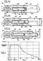
- the orifice (orifices) 132 which leads (s) initially into room 140 is the one (s) located (s) the foremost, that is to say the closest to the wall 134 (according to FIGS. 4a at 4c, this orifice 132a is then temporarily closed by the projectile 200 after the start of the shot and before the projectile 200 leaves the tube 100).
- the projectile 200 can be held in the tube 100 before firing by any suitable conventional means, for example by pins sheared.
- the projectile 200 is provided with a tail unit 220 at its rear end.
- This empennage 220 is adapted to initially seal all of the orifices 132 of the cane with the sole exception of the aforementioned orifice 132a.
- the arrangement of the orifices 132 in particular their distribution, size and number, is suitable for ensuring propulsion pressure at least substantially constant in the propulsion chamber 140.
- the wall of the rod 130 perforated by the openings 132 is inserted directly or indirectly (via the high pressure chamber 150) between the chamber which houses the pressure source 120 and the propulsion chamber 140.
- the operation of the propellant assembly in accordance with this invention essentially comprises three successive phases.
- the pressure prevailing in the launcher tube 100 during these three successive faces is illustrated by way of nonlimiting example in FIG. 5.
- the pyrotechnic cartridge 120 When ignited, the pyrotechnic cartridge 120 (or the source equivalent pressure formed for example from a gas source compressed) generates very high pressure gases which fill the rod 130 (directly according to FIG. 3 and after transit via the chamber 150 according to FIG. 4) and flow into chamber 140 via the bore (or bores) 132a. Following this flow through of bore 132a, the driving pressure will increase in chamber 140 during a phase referenced phase 1 in Figure 5 to reach a regulation pressure at the end of this phase 1. Projectile 200 is moved in the tube 100 with the increase in this driving pressure.
- the initial passage section 132a is completely closed at the end of this phase 1, but on the other hand the rear bores 132 are discovered.
- the displacement of the projectile 200 unmask as the bores 132 formed in the rod 130 to maintain in the form of a plate substantially constant driving pressure in room 140.
- Progressive release bores 132 increases the fluid flow rate between the source of pressure 120 and the launching chamber 140 to maintain the pressure drive at an at least substantially constant value.
- a third phase begins when the 200 projectile has exposed all orifices 132.
- the driving pressure can no longer be maintained at a constant regulation threshold. Then begins a low relaxation phase pressure as illustrated in figure 5.
- FIGS. 4a, 4b and 4c the projectile 200 is illustrated respectively in the positions occupied in phase 1, phase 2 and phase 3 of Figure 5.
- the number, size and position of the bores 132 must be adapted according to the power of the pressure source 120, the caliber and mass of the 200 projectile.
- the rod 130 has a length of 120 mm and a diameter 26 mm and it has 24 bores 132 formed of circular orifice with a diameter of the order of 2 mm distributed with a variable pitch from 21 to 12 mm along the length of the rod 130 and also provided with 3 holes 132a with a diameter of 1.5mm.
- propulsion device in accordance with this invention can be combined with any other known structure capable of to reduce the retraction force of the tube 100, for example all means shock absorbers compatible with this propulsion system.
- the present invention finds particular application in shoulder shooting systems.
- the present invention offers many advantages over known prior systems.
- Rod 130 can be integrated into the cylinder head not consumable from a cannon or in a consumable socket secured to a projectile.
Landscapes
- Engineering & Computer Science (AREA)
- General Engineering & Computer Science (AREA)
- Toys (AREA)
- Excavating Of Shafts Or Tunnels (AREA)
Claims (14)
- Projektiltreibeinheit von dem Typ, der eine Kammer (122) aufweist, die eine Druckquelle (120) aufnimmt und mit wengistens einem Rohr (130) kommuniziert, welches in dem Abschußrohr (100) angeordnet ist und Bohrungen (132) umfaßt, die auf dessen Länge verteilt sind, um beim Ausstoß des Projektils (200) sukzessive freigegeben zu werden, dadurch gekennzeichnet, daß die mit Bohrungen (132) ausgerüstete Wandung des Rohrs (130) zwischen die Kammer, welche die Druckquelle (120) aufnimmt, und die Expansionskammer (140), welche den Vortrieb des Projektils sicherstellt, geschaltet ist.
- Einheit gemäß Anspruch 1, dadurch gekennzeichnet, daß das Rohr (130) die Druckquelle (120) aufnimmt.
- Einheit gemäß einem der Ansprüche 1 oder 2, dadurch gekennzeichnet, daß eine Hochdruck-Zwischenkammer (150) zwischen die Kammer (122), welche die Druckquelle (120) empfängt, und das innere Volumen des Rohrs (130) geschaltet ist.
- Einheit gemäß einem der Ansprüche 1 bis 3, dadurch gekennzeichnet, daß sie ein Projektil (200) umfaßt, das mit einer Kammer (210) ausgerüstet ist, die an dessen Rückfläche mündet, wobei die Kammer (210) an den Außendurchmesser des Rohrs (130) angepaßt ist.
- Einheit gemäß einem der Ansprüche 1 bis 4, dadurch gekennzeichnet, daß wenigstens eine der Bohrungen (132a) des Rohrs (130) anfänglich frei in die Kammer (140), die das Projektil (200) empfängt, mündet.
- Treibeinheit gemäß Anspruch 5, dadurch gekennzeichnet, daß die Bohrung (132a), die anfänglich in die das Projektil (200) empfangende Kammer (140) mündet, die hinterste, im Rohr (130) ausgebildete Bohrung (132a) ist.
- Einheit gemäß Anspruch 5, dadurch gekennzeichnet, daß die Bohrung (132a), die anfänglich in der das Projektil (200) empfangenden Kammer (140) mündet, eine Öffnung ist, die nach der Schußauslösung vorübergehend durch das Projektil (200) infolge dessen Verschiebung verschlossen wird.
- Einheit gemäß Anspruch 7, dadurch gekennzeichnet, daß die Öffnung (132a), die anfänglich in der das Projektil (200) empfangenden Kammer (140) mündet, vorübergehend durch das Leitwerk des Projektils (200) infolge dessen Verschiebung verschlossen wird.
- Einheit gemäß einem der Ansprüche 1 bis 8, dadurch gekennzeichnet, daß das Rohr (130) in dem Abschußrohr (100) zentriert ist.
- Einheit gemäß einem der Ansprüche 1 bis 8, dadurch gekennzeichnet, daß sie mehrere Rohre (130) umfaßt, die mit um die Achse 0-0 des Abschußrohrs (100) gleich verteilten Bohrungen (132) ausgerüstet sind.
- Einheit gemäß einem der Ansprüche 1 bis 10, dadurch gekennzeichnet, daß die Druckquelle (120) in das Abschußrohr (100) integriert ist.
- Einheit gemäß einem der Ansprüche 1 bis 11, dadurch gekennzeichnet, daß die Druckquelle (120) in einem Rohr (130) angeordnet ist, das im nicht-verbrauchbaren Verschluß eines Geschützes integriert ist.
- Einheit gemäß einem der Ansprüche 1 bis 11, dadurch gekennzeichnet, daß die Druckquelle (120) in einem Rohr (130) angeordnet ist, das in eine verbrauchbare Fassung integriert ist.
- Projektil für eine Treibeinheit entsprechend einem der Ansprüche 1 bis 13, dadurch gekennzeichnet, daß es eine Kammer (210) umfaßt, die an dessen rückwärtigem Ende mündet und an die Außenabmessung des Rohrs (130) angepaßt ist.
Applications Claiming Priority (2)
| Application Number | Priority Date | Filing Date | Title |
|---|---|---|---|
| FR9707226 | 1997-06-11 | ||
| FR9707226A FR2764682B1 (fr) | 1997-06-11 | 1997-06-11 | Ensemble de propulsion pour projectile limitant l'effort de recul |
Publications (2)
| Publication Number | Publication Date |
|---|---|
| EP0884553A1 EP0884553A1 (de) | 1998-12-16 |
| EP0884553B1 true EP0884553B1 (de) | 2003-02-12 |
Family
ID=9507847
Family Applications (1)
| Application Number | Title | Priority Date | Filing Date |
|---|---|---|---|
| EP98401424A Expired - Lifetime EP0884553B1 (de) | 1997-06-11 | 1998-06-11 | Antriebsgerät für eine die Rückstossenergie begrenzendes Geschoss |
Country Status (5)
| Country | Link |
|---|---|
| US (1) | US6044746A (de) |
| EP (1) | EP0884553B1 (de) |
| CA (1) | CA2239154C (de) |
| DE (1) | DE69811291T2 (de) |
| FR (1) | FR2764682B1 (de) |
Families Citing this family (5)
| Publication number | Priority date | Publication date | Assignee | Title |
|---|---|---|---|---|
| EP2739930B1 (de) * | 2011-08-04 | 2016-10-12 | Polywad, Inc. | Rückstossabgeschwächtes nutzlastträgersystem |
| US8967046B2 (en) | 2012-11-30 | 2015-03-03 | Alliant Techsystems Inc. | Gas generators, launch tubes including gas generators and related systems and methods |
| US9448033B2 (en) * | 2013-07-11 | 2016-09-20 | The United States Of America As Represented By The Secretary Of The Army | Projectile launcher with a permanent high-low pressure system |
| US10281248B2 (en) | 2015-11-11 | 2019-05-07 | Northrop Grumman Innovation Systems, Inc. | Gas generators, launch tube assemblies including gas generators, and related systems and methods |
| US12467703B2 (en) * | 2021-08-18 | 2025-11-11 | Raytheon Company | Cartridges for recoil management of shoulder fired weapons |
Family Cites Families (21)
| Publication number | Priority date | Publication date | Assignee | Title |
|---|---|---|---|---|
| GB592092A (en) * | 1944-12-16 | 1947-09-08 | Charles Dennistoun Burney | Improvements in or relating to ordnance |
| US1347125A (en) * | 1919-02-28 | 1920-07-20 | Schneider & Cie | Projectile for bomb-throwers |
| BE420894A (de) * | 1936-04-03 | |||
| US2651972A (en) * | 1949-10-31 | 1953-09-15 | Edmund H Engelke | Stop shoulder for recoilless rifle ammunition |
| NL124802C (de) * | 1961-07-20 | Energa | ||
| US3138991A (en) * | 1962-01-10 | 1964-06-30 | Richard L Malter | Firearm muzzle attachment and projectile with expansible, detachable husk |
| NL137772C (de) * | 1965-06-22 | |||
| SE218334C1 (de) * | 1965-07-05 | 1968-01-16 | ||
| US3505924A (en) * | 1967-04-18 | 1970-04-14 | Allied Res Ass Inc | Silent mortar |
| US3628415A (en) * | 1970-01-27 | 1971-12-21 | Stuart H Mcelroy | Mortar |
| DE2713324A1 (de) * | 1976-03-30 | 1977-10-27 | Submarine Eng As | Vorrichtung zum auffangen von erdoel oder dergleichen am wasser |
| US4038902A (en) * | 1976-08-17 | 1977-08-02 | Welsh Robert B | Artillery weapon |
| SE444724B (sv) * | 1982-03-30 | 1986-04-28 | Ffv Affersverket | Driv- och tendpatron till vinggranat |
| DE3336295A1 (de) * | 1983-10-06 | 1985-04-25 | Norbert 2000 Hamburg Bork | Revolverpatrone mit gasdichtungshuelse |
| US4803927A (en) * | 1986-02-03 | 1989-02-14 | Aerojet-General Corporation | Ammunition round and method of manufacture thereof |
| US4782758A (en) * | 1986-02-03 | 1988-11-08 | Aerojet-General Corporation | Ammunition round |
| US4962689A (en) * | 1989-08-01 | 1990-10-16 | Hughes Aircraft Company | Gas generator missile launch system |
| SE463580B (sv) | 1989-11-21 | 1990-12-10 | Saab Missiles Ab | Projektil foer spridning av en last med tidsfoerdroejning |
| DE3939295A1 (de) * | 1989-11-28 | 1991-05-29 | Rheinmetall Gmbh | Verfahren und vorrichtung zur herstellung von grosskalibriger munition |
| FR2713324B1 (fr) | 1993-11-30 | 1996-02-23 | Lacroix E Tous Artifices | Ensemble de propulsion pour projectile. |
| US5837919A (en) * | 1996-12-05 | 1998-11-17 | The United States Of America As Represented By The Secretary Of The Navy | Portable launcher |
-
1997
- 1997-06-11 FR FR9707226A patent/FR2764682B1/fr not_active Expired - Fee Related
-
1998
- 1998-06-10 CA CA002239154A patent/CA2239154C/fr not_active Expired - Fee Related
- 1998-06-11 US US09/095,645 patent/US6044746A/en not_active Expired - Fee Related
- 1998-06-11 EP EP98401424A patent/EP0884553B1/de not_active Expired - Lifetime
- 1998-06-11 DE DE69811291T patent/DE69811291T2/de not_active Expired - Fee Related
Also Published As
| Publication number | Publication date |
|---|---|
| CA2239154A1 (fr) | 1998-12-11 |
| CA2239154C (fr) | 2006-08-15 |
| FR2764682A1 (fr) | 1998-12-18 |
| FR2764682B1 (fr) | 1999-09-03 |
| EP0884553A1 (de) | 1998-12-16 |
| DE69811291T2 (de) | 2003-11-06 |
| DE69811291D1 (de) | 2003-03-20 |
| US6044746A (en) | 2000-04-04 |
Similar Documents
| Publication | Publication Date | Title |
|---|---|---|
| EP0766807B1 (de) | Persönliches feuerwaffensystem | |
| EP0048644B1 (de) | Geschoss mit Leitflossen in Gestalt eines Pfeiles | |
| CA2239154C (fr) | Ensemble de propulsion pour projectile limitant l'effort de recul | |
| EP1650525B1 (de) | Schusseinheit | |
| EP0256894B1 (de) | Rückstossfreie Geschütze oder Abschusssysteme | |
| EP0030051B1 (de) | Gewehrgranate | |
| US3107617A (en) | Ring decoy launching mechanism | |
| EP0557209B1 (de) | Stossdämpfende Vorrichtung für Schulterwaffen mit auswechselbarem Wegwerfdämpferelement | |
| FR2581751A1 (fr) | Dispositif pour l'allumage de charges propulsives ou generateurs de gaz | |
| EP0027418B1 (de) | Vorrichtung zum Abfeuern eines Geschosses ohne rückwärtige Gasabfuhr und ohne Rückstoss mittels eines beidseitig offenen Abschussrohres | |
| EP1712873A1 (de) | Adapter für ein Mörsergeschoss in einem Geschützlauf | |
| EP0661513A1 (de) | Treibanordnung für Geschosse | |
| FR2678054A1 (fr) | Procede pour accelerer un projectile, et tube accelerateur a effet dynamique pour sa mise en óoeuvre. | |
| BE1003971A3 (fr) | Perfectionnements aux projectiles. | |
| FR2725268A1 (fr) | Lanceur de projectile, a canon consommable | |
| EP0759533B1 (de) | Panzerbrechendes Geschoss und mit einem solchen Geschoss versehene Munition | |
| FR2534681A1 (fr) | Perfectionnements apportes aux systemes d'armes lanceurs de projectiles, notamment aux charges propulsives et a la balistique interieure | |
| FR2762081A1 (fr) | Projectile pour munition d'armes a feu de gros calibre | |
| FR2821420A1 (fr) | Ogive perforante autopropulsee pour tir tendu longue portee | |
| BE471675A (de) | ||
| EP0611196B1 (de) | Munition für Kanonen, Mörser oder dergleichen mit eingeschränkter Rückstossenergie | |
| FR2733315A1 (fr) | Moteur-pousseur pour projectiles sans etuis tous calibres | |
| FR2720821A1 (fr) | Perfectionnements apportés aux systèmes d'arme par régulation de leur balistique interne. | |
| FR2611888A1 (fr) | Munitions a propulsion par haute pression de faible duree et lanceurs associes sans recul | |
| FR2698163A1 (fr) | Projectile de perforation et munition équipée d'un tel projectile. |
Legal Events
| Date | Code | Title | Description |
|---|---|---|---|
| PUAI | Public reference made under article 153(3) epc to a published international application that has entered the european phase |
Free format text: ORIGINAL CODE: 0009012 |
|
| AK | Designated contracting states |
Kind code of ref document: A1 Designated state(s): DE FR GB SE |
|
| AX | Request for extension of the european patent |
Free format text: AL;LT;LV;MK;RO;SI |
|
| 17P | Request for examination filed |
Effective date: 19990614 |
|
| AKX | Designation fees paid |
Free format text: DE FR GB SE |
|
| 17Q | First examination report despatched |
Effective date: 20010810 |
|
| GRAG | Despatch of communication of intention to grant |
Free format text: ORIGINAL CODE: EPIDOS AGRA |
|
| GRAG | Despatch of communication of intention to grant |
Free format text: ORIGINAL CODE: EPIDOS AGRA |
|
| GRAH | Despatch of communication of intention to grant a patent |
Free format text: ORIGINAL CODE: EPIDOS IGRA |
|
| GRAH | Despatch of communication of intention to grant a patent |
Free format text: ORIGINAL CODE: EPIDOS IGRA |
|
| GRAA | (expected) grant |
Free format text: ORIGINAL CODE: 0009210 |
|
| AK | Designated contracting states |
Designated state(s): DE FR GB SE |
|
| REG | Reference to a national code |
Ref country code: GB Ref legal event code: FG4D Free format text: NOT ENGLISH |
|
| GBT | Gb: translation of ep patent filed (gb section 77(6)(a)/1977) |
Effective date: 20030212 |
|
| REF | Corresponds to: |
Ref document number: 69811291 Country of ref document: DE Date of ref document: 20030320 Kind code of ref document: P |
|
| PLBE | No opposition filed within time limit |
Free format text: ORIGINAL CODE: 0009261 |
|
| STAA | Information on the status of an ep patent application or granted ep patent |
Free format text: STATUS: NO OPPOSITION FILED WITHIN TIME LIMIT |
|
| 26N | No opposition filed |
Effective date: 20031113 |
|
| PGFP | Annual fee paid to national office [announced via postgrant information from national office to epo] |
Ref country code: SE Payment date: 20070521 Year of fee payment: 10 |
|
| PGFP | Annual fee paid to national office [announced via postgrant information from national office to epo] |
Ref country code: DE Payment date: 20070612 Year of fee payment: 10 |
|
| PGFP | Annual fee paid to national office [announced via postgrant information from national office to epo] |
Ref country code: GB Payment date: 20070612 Year of fee payment: 10 |
|
| PGFP | Annual fee paid to national office [announced via postgrant information from national office to epo] |
Ref country code: FR Payment date: 20070629 Year of fee payment: 10 |
|
| EUG | Se: european patent has lapsed | ||
| GBPC | Gb: european patent ceased through non-payment of renewal fee |
Effective date: 20080611 |
|
| REG | Reference to a national code |
Ref country code: FR Ref legal event code: ST Effective date: 20090228 |
|
| PG25 | Lapsed in a contracting state [announced via postgrant information from national office to epo] |
Ref country code: DE Free format text: LAPSE BECAUSE OF NON-PAYMENT OF DUE FEES Effective date: 20090101 |
|
| PG25 | Lapsed in a contracting state [announced via postgrant information from national office to epo] |
Ref country code: GB Free format text: LAPSE BECAUSE OF NON-PAYMENT OF DUE FEES Effective date: 20080611 |
|
| PG25 | Lapsed in a contracting state [announced via postgrant information from national office to epo] |
Ref country code: FR Free format text: LAPSE BECAUSE OF NON-PAYMENT OF DUE FEES Effective date: 20080630 |
|
| PG25 | Lapsed in a contracting state [announced via postgrant information from national office to epo] |
Ref country code: SE Free format text: LAPSE BECAUSE OF NON-PAYMENT OF DUE FEES Effective date: 20080612 |