EP0884601A1 - Magnetometer - Google Patents
Magnetometer Download PDFInfo
- Publication number
- EP0884601A1 EP0884601A1 EP97304085A EP97304085A EP0884601A1 EP 0884601 A1 EP0884601 A1 EP 0884601A1 EP 97304085 A EP97304085 A EP 97304085A EP 97304085 A EP97304085 A EP 97304085A EP 0884601 A1 EP0884601 A1 EP 0884601A1
- Authority
- EP
- European Patent Office
- Prior art keywords
- sensor support
- magnetic field
- magnetomeasuring
- field sensors
- vessel
- Prior art date
- Legal status (The legal status is an assumption and is not a legal conclusion. Google has not performed a legal analysis and makes no representation as to the accuracy of the status listed.)
- Granted
Links
Images







Classifications
-
- G—PHYSICS
- G01—MEASURING; TESTING
- G01R—MEASURING ELECTRIC VARIABLES; MEASURING MAGNETIC VARIABLES
- G01R33/00—Arrangements or instruments for measuring magnetic variables
- G01R33/02—Measuring direction or magnitude of magnetic fields or magnetic flux
- G01R33/035—Measuring direction or magnitude of magnetic fields or magnetic flux using superconductive devices
- G01R33/0354—SQUIDS
-
- A—HUMAN NECESSITIES
- A61—MEDICAL OR VETERINARY SCIENCE; HYGIENE
- A61B—DIAGNOSIS; SURGERY; IDENTIFICATION
- A61B5/00—Measuring for diagnostic purposes; Identification of persons
- A61B5/24—Detecting, measuring or recording bioelectric or biomagnetic signals of the body or parts thereof
- A61B5/242—Detecting biomagnetic fields, e.g. magnetic fields produced by bioelectric currents
- A61B5/245—Detecting biomagnetic fields, e.g. magnetic fields produced by bioelectric currents specially adapted for magnetoencephalographic [MEG] signals
Definitions
- the present invention relates to a magnetomeasuring apparatus using superconducting quantum interference devices (SQUIDs) as magnetic field sensors, a method for assembling the same and a method for maintaining the same, and a diagnostic apparatus using the same.
- SQUIDs superconducting quantum interference devices
- a magnetomeasuring apparatus using SQUIDs as magnetic field sensors have been conventionally known.
- the SQUIDs have so high sensitivities that the magnetomeasuring apparatus using the SQUIDs can measure weak biomagnetic fields.
- a weak magnetic field measuring apparatus for measuring magnetic fields generated in, e.g., a head of a human being is known (see Japanese Patent Laid-open Publication No. Tokkai Hei 04-315075/1992).
- the weak magnetic field measuring device 1 comprises a dewar vessel 2 including an inner vessel 2a and an outer vessel 2b and the bottom of the dewar vessel 2 shaped in conformity with a head of a human being.
- a support shell 3 is accommodated in the bottom of the dewar vessel 2.
- the support shell 3 is formed in a shape which is contour to a shape of the bottom of the dewar vessel 2.
- a plurality of SQUIDs 4 are arranged in the support shell 3, enclosing the bottom.
- the support shell 3 constitutes one unit 6 together with a mother board 5 in the form of a printed circuit board, etc. This unit 6 is submerged in liquid helium, a coolant.
- a neck plug 9 is disposed above the unit 6 through a support 8 and is housed in an upper part of the interior of the dewar vessel 2.
- the neck plug 9 comprises a radiation shielding and cabling unit.
- the support 8 has electric components mounted thereon.
- the respective component members in the dewar vessel 2 are provided in units, and the unit 6 of the support shell 3 with the neck plug 9 and the support 8 can be removed from the dewar vessel 2 independently.
- the SQUIDs 4 of the weak magnetic field measuring apparatus 1 are mounted on the support shell 3 formed in a helmet-shape which can cover a head over a wide area.
- the support shell 3 must have an at least 30 cm-opening diameter, and the opening of the dewar vessel 2 through which the unit 6 including the support shell 3 has a diameter as large as above 30 cm.
- Liquid helium a coolant
- Liquid helium is very volatile, and it is necessary to minimize intrusion of heat from the outside.
- Major routes of the heat intrusion into the dewar vessel 2 are the vacuum heat-insulating layer between the inner vessel 2a and the outer vessel 2b, and the opening of the dewar vessel 2.
- Loss of the liquid helium due to heat conduction in the opening and its wall of the dewar vessel 2a occupies a considerably high ratio, and the intruding heat reaches a considerably large total amount.
- the increasement of a length of the opening of the dewar vessel 2 reduces the affection by the heat conduction, but the dewar vessel 2 becomes taller.
- the taller dewar vessel 2 requires large rooms installing the weak magnetic field measuring device 1.
- An object of the present invention is to provide a magnetomeasuring apparatus the vessel of which has a small opening so that the apparatus has a small total amount of heat intruding the vessel, and a method for assembling the same and a method for maintaining the same.
- Another object of the present invention is to provide a diagnostic apparatus using the magnetomeasuring apparatus which has a small opening so that the apparatus has a small total amount of heat intruding the vessel.
- a magnetomeasuring apparatus including a plurality of magnetic field sensors and a coolant held in a cooling vessel, comprising: a sensor support for disengageably supporting said plural magnetic field sensors; and fixing means for fixing the sensor support with said plural magnetic field sensors mounted on to a measuring surface of the cooling vessel, an opening of the cooling vessel having a smaller size than the measuring surface for the sensor support to be fixed to.
- the measuring surface of the cooling vessel is formed in a concave shape covering at least a part of a head of a human being in one side of the cooling vessel, and the sensor support has a configuration which permits said plural magnetic field sensors to be arranged in conformity with the configuration of the measuring surface.
- a magnetomeasuring apparatus assembly method for assembling the magnetomeasuring apparatus comprising the steps of disengaging the sensor support from the measuring surface of the coolant vessel, holding the sensor support near the opening of the cooling vessel, mounting the plural magnetic field sensors on the sensor support, and fixing the sensor support with the plural magnetic field sensors mounted on to the measuring surface of the cooling vessel.
- a magnetomeasuring apparatus maintenance method for maintaining the magnetomeasuring apparatus comprising the steps of disengaging the sensor support with the plural magnetic field sensors from the measuring surface of the cooling vessel, holding the cooling vessel near the opening of the cooling vessel, removing a defective one of the plural magnetic field sensors from the sensor support, mounting a normal magnetic field sensor in place of the defective one, and fixing the sensor support with the normal magnetic field sensor to the measuring surface of the cooling vessel.
- a diagnostic apparatus for magnetomeasurement comprising: a bed for a patient to be diagnosed to lie on; the above-described magnetomeasuring apparatus disposed on an end of the bed and arranged so that the head of the patient to be positioned near the measuring surface.
- FIG. 1 is a perspective view of the magnetomeasuring apparatus according to a first embodiment of the present invention
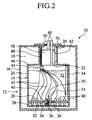
- FIG. 2 is a vertical sectional view of the magnetomeasuring apparatus according to the first embodiment of the present invention.
- FIG. 3 is a cross-sectional view of the magnetomeasuring apparatus according to the first embodiment of the present invention, which shows an arrangement of magnetic field sensors.
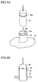
- FIGs. 4A and 4B are views explaining an example of a structure for mounting magnetic field sensors on the sensor support in the magnetomeasuring apparatus according to the first embodiment of the present invention.
- FIG. 5 is a view explaining mounting of magnetic field sensors on the sensor support in the magnetomeasuring apparatus according to the first embodiment of the present invention.
- FIGs. 6A to 6C are views explaining a method for assembling the magnetomeasuring apparatus according to the first embodiment of the present invention.
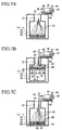
- FIGs. 7A to 7C are views explaining a method for maintaining the magnetomeasuring apparatus according to the first embodiment of the present invention.
- FIG. 8 is a vertical sectional view of the magnetomeasuring apparatus according to the first embodiment of the present invention, which explains another example of securing the sensor support to the bottom of the inner vessel body.
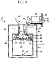
- FIG. 9 is a vertical sectional view of the magnetomeasuring apparatus according to the first embodiment of the present invention, which explain another example of lifting the sensor support.
- FIG. 10 is a perspective view of the magnetomeasuring apparatus according to a second embodiment of the present invention.
- FIG. 11 is a vertical sectional view of the magnetomeasuring apparatus according to a second embodiment of the present invention.
- FIG. 12 is a perspective view of diagnostic apparatus using the magnetomeasuring apparatus according to the second embodiment of the present invention.
- FIG. 13 is a plan view of the diagnostic apparatus using the magnetomeasuring apparatus according to the second embodiment of the present invention.
- FIG. 14 is a front view of the diagnostic apparatus using the magnetomeasuring apparatus according to the second embodiment of the present invention.
- FIG. 15 is a side view of the diagnostic apparatus using the magnetomeasuring apparatus according to the second embodiment of the present invention.
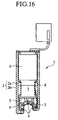
- FIG. 16 is a sectional view of a conventional magnetomeasuring apparatus.
- FIG. 1 is a perspective view of the magnetomeasuring apparatus according to the first embodiment.
- FIG. 2 is a vertical sectional view of the magnetomeasuring apparatus according to the first embodiment.
- FIG. 3 is a cross-sectional view of the magnetomeasuring apparatus according to the first embodiment, which shows the arrangement of magnetic field sensors of the magnetomeasuring apparatus according to the first embodiment.
- FIGs. 4A and 4B are views explaining an example of a structure for mounting magnetic field sensors on the sensor support in the magnetomeasuring apparatus according to the first embodiment of the present invention.
- FIG. 5 is a view explaining the mounted state of the magnetic field sensors on a sensor support of the magnetomeasuring apparatus.
- the magnetomeasuring apparatus 10 includes a cryostat 12 which is a bottomed cylindrical vessel. As shown in FIG. 2, the cryostat 12 has a double structure of an inner bottomed cylindrical vessel 14 accommodated in an outer bottomed cylindrical vessel 16. A heat insulating material 18 is filled inbetween the inner vessel 14 and the outer vessel 16.
- the inner vessel 14 includes an inner vessel body 20, and a cylindrical opened space 22 projected from a top part of the inner vessel body 20.
- the opened space 22 which is an outlet has an inner diameter smaller than that of the inner vessel body 20.
- the opened space 22 has an about 14 cm-inner diameter and an about 30 cm-height.
- the outer vessel 16 has a top opening 24 which is in communication with the opened space 22.
- a sensor body 26 is accommodated in the inner vessel body 20.
- the sensor support 26 is a disc shape and is a little smaller than the inner diameter than the inner vessel body 20. Its diameter is 30 - 40 cm.
- a plurality of holes 28 are formed at a substantially constant pitch in the entire surface of the sensor support 26.
- a male clamp 30 is provided substantially on the center of the surface of the sensor support 26. As shown in FIGs. 2 and 5, the male clamp 30 includes a knob 31 projected to the front surface of the sensor support 26 and an insert 32 projected to the back surface of the sensor support 26.
- a female clamp 34 corresponding to the male clamp 30 is provided on the bottom of the vessel body 20.
- the female clamp 34 includes a receiver 36 for holding the insert 32 engaged therein.
- the insert 32 of the male clamp 30 is pushed in the receiver 36 of the female clamp 34, whereby, as shown in FIG. 2, the insert 32 is engaged with the receiver 36 and the male clamp 30 is connected to the female clamp 34.
- the insert 32 of the male clamp 30 is pulled out of the receiver 36 of the female clamp 34, whereby, as shown in FIG. 5, the insert 32 is disengaged from the receiver 36, and the male clamp 30 is separated from the female clamp 34.
- the clamps 30 and 34 may be replaced by screws.
- a tapped hole 38 is formed substantially in the center of the surface of the sensor support 26.
- the tapped hole 38 may be assembled with the male clamp 30.
- a lift rod 66 which will be described below, can be screwed into the tapped hole 38.
- magnetic field sensors 40 comprising SQUIDs are engaged fixedly in the respective holes 28 in the sensor support 26.
- a plurality of magnetic field sensors 40 are fixed in the sensor support 26 regularly at a constant pitch cover the substantially entire surface of the sensor support 26.
- the magnetic field sensor 40 comprising the SQUIDs, which can measure weak biomagnetic fields, can measure magnetic fields generated in a head of a human being.
- sensor supports 29 for supporting the magnetic field sensors 40 are provided in the respective holes 26 in the sensor support 26.
- Each sensor support 29 is in the shape of a thin cylinder.
- Slits 29a are formed in 2 to 4 upper parts of the cylinder, and a groove 29b is formed in the inside surface thereof.
- a ring 40a is formed on the circumference of each magnetic field sensor 40.
- the slits 29a allow the upper part of the sensor support 29 to be a little expanded outward to facilitate the engagement of the magnetic field sensor 40.
- the ring 40a is engaged into the groove 29b in the sensor support 29 and positioned there.
- the sensor support 26 is formed to be sufficiently wide to accommodate a number of magnetic field sensors 40 necessary for objects to be measured.
- measuring cords 42 are led out from the respective magnetic field sensors 40.
- the respective measuring cords 42 led out from the respective magnetic field sensors 40 are collected by a cord connector 44.
- the cord connector 44 is connected to a wiring connector 46. All the necessary number of wiring cords 48 are collected to the wiring connector 46.
- the wiring cords 48 are connected to a cord output 50 disposed on the outside surface of a cap 56, which will be described later, through a gap between a heat insulator 58 and the opened space 22.
- the wiring cord 48 is formed of a high electric resistance wire having low heat conductivity, whereby heat intrusion due to the heat conduction can be suppressed low.
- the inner vessel body 20 holds liquid helium 52 in which the magnetic field sensors 40 are submerged (see FIG. 2).
- the liquid helium is a coolant for the magnetic field sensors 40.
- a level sensor 54 is disposed inside the inner vessel body 20 heightwise of the inside wall thereof. The level sensor 54 detects a level of the liquid helium 52 held in the inner vessel body 20.
- the top opening 24 of the outer vessel 16 is closed by a cap having a larger diameter than the top opening 24.
- the cap 56 prevents vaporization due to contact between air and the liquid helium 52.
- the cap 56 there are provided two charge/discharge pipes 60 which are opened on the outer side of the cap 56. As shown in FIG. 2, one of the charge/discharge pipes 60 has the other end communicated with a communication hole 62 of the heat insulation portion 58, and the other of the charge/discharge pipes 60 has the other end opened in the underside of the heat insulation portion 58.
- the communication hole 62 crosses the heat insulation portion 58 and opened in the outer circumference at an opposed position. Liquid helium is fed into the inner vessel body 20 through the charge/discharge pipe 60 or discharge helium gas from the inner vessel body 20.
- the inner vessel 14, the outer vessel 16, and almost all constituent members of the cryostat 12 are formed of non-magnetic and non-conducting material, such as fiber-reinforced resin or others.
- the heat insulation portion 58 is formed of heat insulating material comprising multi-layers of polyester resin foils with aluminium vapor deposited.
- the bottoms of the inner vessel 14 and the outer vessel 16 are not essentially flat and may have arbitrary shapes as required.
- the bottoms may be helmet-shaped.
- the mounting of the magnetic field sensors 40 on the sensor support 26 is carried out, when the magnetomeasuring apparatus 10 is assembled at the start, and when defective ones of the magnetic field sensors 40 are replaced by new ones for maintenance.
- the opening 24 of the outer vessel 16 of the cryostat 12 is opened.
- the cap 56 closing the upper opening 24 is lifted to pull out the heat insulation portion 58.
- the cap 56 disengaged from the top opening 24 is rested horizontal on the cap support 64.
- the sensor support 26 is secured to the bottom surface of the inner vessel 14 by the engagement between the male clamp 30 and the female clamp 34.
- the sensor support 26 is beforehand accommodated in the inner vessel 14 when the inner vessel 14 is fabricated and assembled.
- the lift rod 66 has a length larger than a distance from the top opening 24 to the inside bottom of the inner vessel 14, and has a threaded portion 68 which can be screwed on a tapped hole 38 of the sensor support 26.
- the lift rod 66 is registered with the tapped hole 38 of the sensor support 26 and turned to be screw-engaged with the sensor support 26.
- the lift rod 66 screw-engaged with the sensor support 26 is lifted.
- the male clamp 30 is pulled through the sensor support 26 and disengaged from the female clamp 34.
- the sensor support 26 is lifted up to the vicinity of the open space 22.
- the lifted sensor support 26 is held in the lifted state as shown in FIG. 6B.
- the lift rod 66 screw-engaged in the lifted sensor support 26 is secured to the rod support 67 provided on the top surface of the outer vessel 16 toward the top opening 24.
- a magnetic field sensor 40 is inserted by the hand into the opened space 22 through the top opening 24 to be mounted on the sensor support 26.
- the top open space 22 has an about 14 cm-diameter which allows the hand and arm holding a magnetic field sensor 40 to be put into the open space 22.
- the operation is monitored through the open space 22 by a fiberscope, a CCD camera, a mirror or others.
- the measuring cords 42 of the respective magnetic field sensors 40 are wired to a cord leading out portion 50 through the cord connector 44 connected to the wiring connector 46.
- the magnetic field sensors 40 are pushed into the holes 28 to be secured to the sensor support 26.
- the sensor support 26 with the magnetic field sensors 40 mounted on is secured to the bottom surface of the inner vessel 14.
- the lift rod 66 is held by a hand to be removed from the rod support 67 and lowered in the inner vessel 14.
- the male clamp 30 of the sensor support 26 is registered with the female clamp 34, and the lift rod 66 is pushed downward to engage the male clamp 30 with the female clamp 34.
- the lift rod 66 is removed from the sensor support 26.
- the lift rod 66 screw-engaged with the sensor support 26 is turned in a opposite direction to be disengaged from the sensor support 26.
- the lift rod 66 removed from the sensor support 26 is taken out of the inner vessel 14.
- the magnetic field sensors 40 are mounted on the sensor support 26 without taking out the sensor support 26 out of the inner vessel 14 to assemble the magnetomeasuring apparatus 10.
- the top opening 24 of the outer vessel 16 of the cryostat 12 is opened.
- the cap 56 removed from the top opening 24 is rested on the cap support 64.
- the sensor support 26 with the magnetic field sensors 40 mounted on is secured to the bottom surface of the inner vessel 14.
- the measuring cords 42 of the respective sensors 40 are wired to the cord lead-out portion 50 through the cord connector 44 connected to the wiring connector 46.
- the liquid helium 52 in the inner vessel 14 has been discharged in advance from the inner vessel 14.
- the male clamp 30 is disengaged from the female clamp 34.
- the lift rod 66 is lifted to disengage the male clamp 30 from the female clamp 34 and lift the sensor support 26 up near the lower end of the opened space 22. Then, the lifted sensor support 26 is held in this state as shown in FIG. 7B.
- a hand is put into the opened space 22 through the top opening 24 to pull a magnetic field sensor 40, which is to be replaced, from the sensor support 26.
- the measuring cord of a new magnetic field sensor 40 replacing the pulled-out magnetic field sensor 40 is wired to the cord lead-out portion 50 through the cord connector 44 connected to the wiring connector 46.
- the new magnetic field sensor 40 whose measuring cord has been wired to the cord lead-out portion 50 is held by a hand to be put into the open space 22 through the top opening 24, and is mounted on the sensor support 26.
- the sensor support 26 with the new magnetic field sensor 40 mounted on is secured to the bottom surface of the inner vessel 14.
- the defective magnetic field sensor can be replaced by a normal magnetic field sensor without taking out the sensor support 26 out of the inner vessel 14.
- the open space 22 has a size sufficient for a human hand to pass through, e.g., has an about 14 cm diameter, a 2 - 3 mm thickness and an about 30 cm length.
- the conventional magnetomeasuring apparatus has a 30 - 40 cm diameter, a 4 - 5 mm thickness and a 40 - 50 cm length.
- the magnetomeasuring apparatus according to the present invention is reduced to the diameter which is 1/2 - 1/3 of the conventional apparatus, and the length which is about 4/5 of the conventional apparatus.
- the conducting heat through the wall the open space 22 is proportional to a diameter of the open space 22, and conduction heat conducted in the heat insulation material inserted in the open space 22 is proportional to a sectional area, or square of a diameter of the open space 22, and linearly proportional to a length of the open space 22. Even in consideration of affection by heat conduction increase due to the smaller length, heat intrusion occurring because of the open space 22 can be drastically decreased in comparison with that in the conventional magnetomeasuring apparatuses.
- clamps 30, 34 are used to secure the sensor support 26 to the bottom surface of the inner vessel body 20, but may be secured by different means.
- the sensor support 26 may be fixed by a support rod 39 which has is fixed to the cap 56, and is passed through the heat insulation portion 22 to be reached to the sensor support 26.
- the support rod 39 is formed of FRP.
- the sensor support 26 is pressed against the bottom surface of the inner vessel body 20 by flexibility exhibited when the support rod 39 is flexed.
- a single support rod 39 or a plurality of support rods 38 may be used.
- the sensor support 26 is lifted by the lift rod 66 but may be lifted by different means. As shown in FIG. 9, however, a plurality of strings 69 of glass fiber or plastics are fixed to the sensor support 26, and when the sensor support 26 is lifted, the strings 69 are pulled up to lift the sensor support 26.
- the lift rod 66 and the strings 69 may be used together.
- FIG. 10 is a perspective view of the magnetomeasuring apparatus
- FIG. 11 is a vertical sectional view of the magnetomeasuring apparatus.
- the magnetomeasuring apparatus 70 has the same structure as the magnetomeasuring apparatus according to the first embodiment except that the former includes a concavity in one side and a configuration which contains an open space 22 upward projected.
- the cryostat 72 has a double structure of an inner vessel 74 accommodated in an outer vessel similar to the inner vessel, and a heat insulation material 18 is filled inbetween the inner and the outer vessels 74, 76.
- the inner vessel 74 has the open space 22 projected from the substantially central part of an inner vessel body 78 in a horizontal cylindrical shape.
- the outer vessel 76 has an outer vessel open space 81 projected from the substantially central part of an outer vessel body 80.
- a top opening 24 which is in communication with the open space 22 is formed in the outer vessel open space 81.
- the top opening 24 is closed by a cap 56.
- a helmet-shaped concavity 82 which is opened outward is formed horizontally in one side surface of the outer vessel body 80.
- the concavity 82 has a helmet-shape and a size which can accommodate the head of a person to be measured.
- An inner vessel concavity 84 is formed in the inner vessel body 78 in agreement with the concavity 82.
- a sensor support 86 is provided inside the inner vessel concavity 84. As shown in FIG. 11, the sensor support 86 is formed in a dome of an about 30 cm diameter which covers the inner vessel concavity 84. In the sensor support 86 there are formed a plurality of holes 28 in the entire surface thereof.
- a male clamp 88 which is similar to the male clamp 30 of the magnetomeasuring apparatus 10.
- the male clamp 88 includes a long handle 90 which reaches the substantial center of the interior of the inner vessel 74.
- a sensor 92 which detects environmental magnetic field is mounted on the forward end of the handle 90.
- One set or a plurality of sets of the sensors 92 may be mounted on.
- a female clamp 94 which is similar to the female clamp 34 of the magnetomeasuring apparatus 10 is provided on the inner vessel concavity 84.
- Magnetic field sensors 40 comprising SQUIDs are disposed in the respective holes of the sensor support 86.
- Each of the magnetic field sensors 40 has a rod shape and is inserted in each of the holes to be secured to the sensor support 86.
- liquid helium 52 is reserved in the inner vessel body 78 up to an 80%-level so that the magnetic field sensors 40 are immersed.
- the liquid helium 52 is a coolant for the magnetic field sensors 40.
- a liquid level of the liquid helium 52 in the inner vessel body 78 can be detected by a level sensor 54 disposed inside the inner vessel body 78.
- the measuring cords 42 are formed of copper wires, and have good heat conduction which makes a temperature of the inner vessel body 78 uniform. As a result, even when a liquid level of the liquid helium is lowered, and the magnetic field sensors 40 are exposed to gas phase, temperature increase can be suppressed, and the magnetic field detection is not affected.
- cryostat 72 Most of the constituent members of the cryostat 72 are formed of non-magnetic and non conducting material, such as fiber reinforced resins, etc. so that they does not bother the detection of magnetic fields.
- the mounting of the magnetic field sensors 40 on the sensor support 86 is carried out, when the magnetomeasuring apparatus 70 is assembled at the start, and when defective ones of the magnetic field sensors 40 are replaced by new ones for maintenance.
- the method for mounting the magnetic field sensors 40 on the sensor support 86 and assembling the magnetomeasuring apparatus 70 is substantially the same as that for assembling the magnetomeasuring apparatus according to the first embodiment, but is different from the first embodiment in the method for removing the sensor support 86 from the inner vessel concavity 84.
- a hand is put into the inner vessel 74 through the open space 22 to pull the male clamp 88 and disengage the male clamp 88 from the female clamp 94.
- the sensor support 86 removed from the inner vessel concavity 84 is rested to a rod support (not shown) through a lift rod or lift strings (not shown).
- the magnetic field sensors 40 are mounted on the sensor support 86 to assemble the magnetomeasuring apparatus 70.
- the magnetic field sensors 40 mounted on the sensor support 86 are replaced for maintenance.
- FIG. 12 is a perspective view of the diagnostic apparatus
- FIG. 13 is a plan view of the diagnostic apparatus
- FIG. 14 is a front view of the diagnostic apparatus
- FIG. 15 is a side view of the diagnostic apparatus.
- the diagnostic apparatus 96 comprises the magnetomeasuring apparatus 70 disposed on one end of a bed for a patient to lie on. As shown in FIGs. 13 to 15, the diagnostic apparatus 96 is placed on a floor 102 in a magnetically shielded room 100.
- the magnetically shielded room 100 has an entrance/exit door 104.
- the cryostat 72 of the magnetomeasuring apparatus 70 is mounted on a table 106.
- a duct 108 is provided in the top side of the cryostat 72 opposed to the bed and upwardly extended outside.
- the duct 108 accommodates a charge/discharge pipe 60 provided in the cap 56, and the wiring (not shown) from the cord lead-out portion 50.
- the duct 108 may be disposed in another side and extended outside the magnetically shielded room 100 as indicated by the dotted line.
- the top side of the cryostat 72 except the duct 108 is covered with a cover 110.
- the bed 98 is positioned with a height adjusted so that the head of a patient lying on the bed 98 can be inserted in the concavity 82 of the cryostat 72.
- the bed 98 includes a movable table 114 with a pillow 12 on the side of the concavity 82.
- the movable table 114 is moved to and from the concavity 82 with a patient lying on with the head placed on the pillow 112.
- the patient can have magnetic field distributions occurring in the head detected by the magnetic field sensors 40 while lying on the bed 98.
- the magnetomeasuring apparatus 70 includes the magnetic field sensors 40 arranged so as to cover the head of the lying patient, thus the cryostat 72 is lowered in height and the magnetomeasuring apparatus 70 is also lowered in height.
- the ceiling of the magnetically shielded room 100 for the magnetomeasuring apparatus 70 can be lowered.
- the magnetically shielded room 100 including the diagnostic apparatus can be placed in ordinary room having low ceilings.
- the measuring surface of the sensor support 26, 86 is not essentially disk shaped and helmet-shaped.
- the cryostat 12, 27 including the inner vessel 14, 4 and the outer vessel 16, 76 are not essentially cylindrical.
- the open space 22 of the inner vessel 14, 74 is not essentially cylindrical.
- the magnetic field sensors 40 are mounted by putting a hand into the open space 22, but may be mounted by the use of mounting means which can be operated by remote control.
Landscapes
- Physics & Mathematics (AREA)
- Condensed Matter Physics & Semiconductors (AREA)
- General Physics & Mathematics (AREA)
- Measurement And Recording Of Electrical Phenomena And Electrical Characteristics Of The Living Body (AREA)
- Measuring Magnetic Variables (AREA)
Priority Applications (2)
| Application Number | Priority Date | Filing Date | Title |
|---|---|---|---|
| EP97304085A EP0884601B1 (de) | 1997-06-11 | 1997-06-11 | Magnetometer |
| DE69716042T DE69716042T2 (de) | 1997-06-11 | 1997-06-11 | Magnetometer |
Applications Claiming Priority (1)
| Application Number | Priority Date | Filing Date | Title |
|---|---|---|---|
| EP97304085A EP0884601B1 (de) | 1997-06-11 | 1997-06-11 | Magnetometer |
Publications (2)
| Publication Number | Publication Date |
|---|---|
| EP0884601A1 true EP0884601A1 (de) | 1998-12-16 |
| EP0884601B1 EP0884601B1 (de) | 2002-10-02 |
Family
ID=8229371
Family Applications (1)
| Application Number | Title | Priority Date | Filing Date |
|---|---|---|---|
| EP97304085A Expired - Lifetime EP0884601B1 (de) | 1997-06-11 | 1997-06-11 | Magnetometer |
Country Status (2)
| Country | Link |
|---|---|
| EP (1) | EP0884601B1 (de) |
| DE (1) | DE69716042T2 (de) |
Cited By (3)
| Publication number | Priority date | Publication date | Assignee | Title |
|---|---|---|---|---|
| EP1634531A1 (de) * | 2004-09-10 | 2006-03-15 | Hitachi High-Technologies Corporation | Magnetische Abschirmung und Messvorrichtung für die Bestimmung biomagnetischer Signale. |
| CN109414212A (zh) * | 2016-06-03 | 2019-03-01 | 国立大学法人东京医科齿科大学 | 生物磁测量装置 |
| JP2019120517A (ja) * | 2017-12-28 | 2019-07-22 | 住友重機械工業株式会社 | 超伝導磁気シールド装置、及び脳磁計装置 |
Families Citing this family (2)
| Publication number | Priority date | Publication date | Assignee | Title |
|---|---|---|---|---|
| DE102008014003B4 (de) * | 2008-03-13 | 2010-02-11 | Bundesrepublik Deutschland, vertr.d.d. Bundesministerium für Wirtschaft und Technologie, d.vertr.d.d. Präsidenten der Physikalisch-Technischen Bundesanstalt | Kryosensorpositioniervorrichtung und kryostatische Anlage |
| DE102017205279B3 (de) * | 2017-03-29 | 2018-09-20 | Bruker Biospin Ag | Kryostatanordnung mit einem Halsrohr mit einer tragenden Struktur und ein die tragende Struktur umgebendes Außenrohr zur Verringerung des Kryogenverbrauchs |
Citations (5)
| Publication number | Priority date | Publication date | Assignee | Title |
|---|---|---|---|---|
| EP0200958A1 (de) * | 1985-04-26 | 1986-12-17 | Siemens Aktiengesellschaft | Vorrichtung zur Messung schwacher Magnetfelder mit mehreren Gradiometern |
| EP0361137A1 (de) * | 1988-09-16 | 1990-04-04 | Siemens Aktiengesellschaft | Magnetometer-Einrichtung mit einem Dewar-Gefäss zur Messung schwacher Magnetfelder |
| EP0492262A2 (de) * | 1990-12-21 | 1992-07-01 | Neuromag Ltd. | Mehrkanalanordnung zum Messen von räumlich und zeitlich veränderlichen schwachen Magnetfeldern |
| EP0492263A1 (de) * | 1990-12-21 | 1992-07-01 | Neuromag Ltd | Magneto-Messfühler zur Messung der durch die Gehirnaktivität resultierenden Magnetfelder |
| EP0595227A1 (de) * | 1992-10-27 | 1994-05-04 | Biomagnetic Technologies, Inc. | Biomagnetometer mit flexiblem Sensor |
-
1997
- 1997-06-11 EP EP97304085A patent/EP0884601B1/de not_active Expired - Lifetime
- 1997-06-11 DE DE69716042T patent/DE69716042T2/de not_active Expired - Lifetime
Patent Citations (6)
| Publication number | Priority date | Publication date | Assignee | Title |
|---|---|---|---|---|
| EP0200958A1 (de) * | 1985-04-26 | 1986-12-17 | Siemens Aktiengesellschaft | Vorrichtung zur Messung schwacher Magnetfelder mit mehreren Gradiometern |
| EP0361137A1 (de) * | 1988-09-16 | 1990-04-04 | Siemens Aktiengesellschaft | Magnetometer-Einrichtung mit einem Dewar-Gefäss zur Messung schwacher Magnetfelder |
| EP0492262A2 (de) * | 1990-12-21 | 1992-07-01 | Neuromag Ltd. | Mehrkanalanordnung zum Messen von räumlich und zeitlich veränderlichen schwachen Magnetfeldern |
| EP0492263A1 (de) * | 1990-12-21 | 1992-07-01 | Neuromag Ltd | Magneto-Messfühler zur Messung der durch die Gehirnaktivität resultierenden Magnetfelder |
| JPH04315075A (ja) * | 1990-12-21 | 1992-11-06 | Neuromag Oy | 弱磁界測定デバイス |
| EP0595227A1 (de) * | 1992-10-27 | 1994-05-04 | Biomagnetic Technologies, Inc. | Biomagnetometer mit flexiblem Sensor |
Cited By (6)
| Publication number | Priority date | Publication date | Assignee | Title |
|---|---|---|---|---|
| EP1634531A1 (de) * | 2004-09-10 | 2006-03-15 | Hitachi High-Technologies Corporation | Magnetische Abschirmung und Messvorrichtung für die Bestimmung biomagnetischer Signale. |
| US7339373B2 (en) | 2004-09-10 | 2008-03-04 | Hitachi High-Technologies Corporation | Magnetic shielding apparatus and biomagnetism measuring device |
| CN109414212A (zh) * | 2016-06-03 | 2019-03-01 | 国立大学法人东京医科齿科大学 | 生物磁测量装置 |
| EP3466333A4 (de) * | 2016-06-03 | 2020-03-04 | National University Corporation Tokyo Medical and Dental University | Biomagnetismusmessvorrichtung |
| US11647928B2 (en) | 2016-06-03 | 2023-05-16 | National University Corporation Tokyo Medical And Dental University | Biomagnetism measuring device |
| JP2019120517A (ja) * | 2017-12-28 | 2019-07-22 | 住友重機械工業株式会社 | 超伝導磁気シールド装置、及び脳磁計装置 |
Also Published As
| Publication number | Publication date |
|---|---|
| DE69716042D1 (de) | 2002-11-07 |
| EP0884601B1 (de) | 2002-10-02 |
| DE69716042T2 (de) | 2003-06-26 |
Similar Documents
| Publication | Publication Date | Title |
|---|---|---|
| US5896645A (en) | Method of assembling a magnetomeasuring apparatus | |
| CA2057455C (en) | Compact magnetometer probe and an array of them covering the whole human skull for measurement of magnetic fields arising from the activity of the brain | |
| US4996479A (en) | Magnetometer device with a Dewar vessel for measuring weak magnetic fields | |
| EP0595227B1 (de) | Biomagnetometer mit flexiblem Sensor | |
| FI89416C (fi) | Flerkanalanordning foer maetning av svaga, lokal- och tidsberoende magnetfaelt | |
| US4700135A (en) | Apparatus for measuring weak magnetic fields having several gradiometers with associated SQUID array | |
| EP0157404A2 (de) | Gegen Hochfrequenz abgeschirmter Raum für ein Abbildungssystem unter Verwendung kernmagnetischer Resonanz | |
| EP0884601B1 (de) | Magnetometer | |
| US20250176886A1 (en) | Multimodal position transformation dual-helmet meg apparatus | |
| JPS60233874A (ja) | 横形クライオスタツト | |
| JP2000266827A (ja) | 極低温容器用電子素子の交換装置 | |
| JP5253926B2 (ja) | 脳磁計 | |
| JPH10155759A (ja) | 磁気測定装置および極低温容器 | |
| JPH1119058A (ja) | 生体磁気計測装置の真空断熱容器 | |
| WO1995000858A1 (en) | Biomagnetometer with solid conduction cooling | |
| JPH0968564A (ja) | Squid磁束計 | |
| Labik et al. | Fixed illumination system | |
| JPS63232305A (ja) | クライオスタツト | |
| HU189815B (en) | Cryostat with isotope he-3 |
Legal Events
| Date | Code | Title | Description |
|---|---|---|---|
| PUAI | Public reference made under article 153(3) epc to a published international application that has entered the european phase |
Free format text: ORIGINAL CODE: 0009012 |
|
| AK | Designated contracting states |
Kind code of ref document: A1 Designated state(s): DE FI GB NL |
|
| AX | Request for extension of the european patent |
Free format text: AL;LT;LV;SI |
|
| 17P | Request for examination filed |
Effective date: 19990206 |
|
| AKX | Designation fees paid |
Free format text: DE FI GB NL |
|
| 17Q | First examination report despatched |
Effective date: 20001207 |
|
| GRAG | Despatch of communication of intention to grant |
Free format text: ORIGINAL CODE: EPIDOS AGRA |
|
| GRAG | Despatch of communication of intention to grant |
Free format text: ORIGINAL CODE: EPIDOS AGRA |
|
| GRAH | Despatch of communication of intention to grant a patent |
Free format text: ORIGINAL CODE: EPIDOS IGRA |
|
| GRAH | Despatch of communication of intention to grant a patent |
Free format text: ORIGINAL CODE: EPIDOS IGRA |
|
| GRAA | (expected) grant |
Free format text: ORIGINAL CODE: 0009210 |
|
| AK | Designated contracting states |
Kind code of ref document: B1 Designated state(s): DE FI GB NL |
|
| PG25 | Lapsed in a contracting state [announced via postgrant information from national office to epo] |
Ref country code: NL Free format text: LAPSE BECAUSE OF FAILURE TO SUBMIT A TRANSLATION OF THE DESCRIPTION OR TO PAY THE FEE WITHIN THE PRESCRIBED TIME-LIMIT Effective date: 20021002 |
|
| REG | Reference to a national code |
Ref country code: GB Ref legal event code: FG4D |
|
| REF | Corresponds to: |
Ref document number: 69716042 Country of ref document: DE Date of ref document: 20021107 |
|
| NLV1 | Nl: lapsed or annulled due to failure to fulfill the requirements of art. 29p and 29m of the patents act | ||
| PLBE | No opposition filed within time limit |
Free format text: ORIGINAL CODE: 0009261 |
|
| STAA | Information on the status of an ep patent application or granted ep patent |
Free format text: STATUS: NO OPPOSITION FILED WITHIN TIME LIMIT |
|
| 26N | No opposition filed |
Effective date: 20030703 |
|
| PGFP | Annual fee paid to national office [announced via postgrant information from national office to epo] |
Ref country code: GB Payment date: 20160425 Year of fee payment: 20 Ref country code: FI Payment date: 20160623 Year of fee payment: 20 |
|
| PGFP | Annual fee paid to national office [announced via postgrant information from national office to epo] |
Ref country code: DE Payment date: 20160621 Year of fee payment: 20 |
|
| REG | Reference to a national code |
Ref country code: DE Ref legal event code: R071 Ref document number: 69716042 Country of ref document: DE |
|
| REG | Reference to a national code |
Ref country code: GB Ref legal event code: PE20 Expiry date: 20170610 |
|
| PG25 | Lapsed in a contracting state [announced via postgrant information from national office to epo] |
Ref country code: GB Free format text: LAPSE BECAUSE OF EXPIRATION OF PROTECTION Effective date: 20170610 |