EP0884629A1 - Kamera versehen mit einer Zeichen-Anzeigevorrichtung - Google Patents
Kamera versehen mit einer Zeichen-Anzeigevorrichtung Download PDFInfo
- Publication number
- EP0884629A1 EP0884629A1 EP97117587A EP97117587A EP0884629A1 EP 0884629 A1 EP0884629 A1 EP 0884629A1 EP 97117587 A EP97117587 A EP 97117587A EP 97117587 A EP97117587 A EP 97117587A EP 0884629 A1 EP0884629 A1 EP 0884629A1
- Authority
- EP
- European Patent Office
- Prior art keywords
- camera
- light
- character
- film
- exposure
- Prior art date
- Legal status (The legal status is an assumption and is not a legal conclusion. Google has not performed a legal analysis and makes no representation as to the accuracy of the status listed.)
- Withdrawn
Links
Images




Classifications
-
- G—PHYSICS
- G03—PHOTOGRAPHY; CINEMATOGRAPHY; ANALOGOUS TECHNIQUES USING WAVES OTHER THAN OPTICAL WAVES; ELECTROGRAPHY; HOLOGRAPHY
- G03B—APPARATUS OR ARRANGEMENTS FOR TAKING PHOTOGRAPHS OR FOR PROJECTING OR VIEWING THEM; APPARATUS OR ARRANGEMENTS EMPLOYING ANALOGOUS TECHNIQUES USING WAVES OTHER THAN OPTICAL WAVES; ACCESSORIES THEREFOR
- G03B17/00—Details of cameras or camera bodies; Accessories therefor
- G03B17/24—Details of cameras or camera bodies; Accessories therefor with means for separately producing marks on the film, e.g. title, time of exposure
- G03B17/245—Optical means
Definitions
- the present invention relates to a camera equipped with character display device, and relates to a camera which shields a part of the subject image which enters from the camera lens and is photographed onto the film surface, and exposes specific characters or images onto this shielded portion.
- Japanese Utility Model Publication No. Hei. 6-69948 discloses a camera that enables photographic prints of characters, messages or images for advertisements or promotional purposes developed and printed within a predetermined region of a single frame of a picture taken by a camera. Characters are displayed separately from the subject of the photograph by exposing two separate regions of a single frame of a photographic film to light from two different sources. Light from the first source enters through the camera lens and light from the second source is captured from the flash lamp provided externally on the camera for illuminating the subject. An optical fiber conducts light from the external flash lamp into the camera interior and onto the frame of the photographic film.
- One end of the optical fiber faces the external flash light source and the other end of the optical fiber is connected to a light diffusing block that distributes the transmitted light over a transparent film bearing characters, messages or images that are simultaneously exposed on a portion of the photographic film with the picture coming through the camera lens.
- the optical fiber employed in the camera disclosed in the foregoing Japanese Utility Model Publication No. Hei. 6-69948 can permit unwanted, stray light to enter the exposure chamber, exposing the film to light even when the camera shutter is in a closed position. This unwanted exposure can occur because the end of the optical fiber facing the external flash lamp is always exposed to the ambient light entering through the transparent window of the flash unit. The external light is conducted through the optical fiber, into the exposure chamber and onto the photographic film.
- a shutter mechanism at some point along the optical fiber and synchronously operated with the camera shutter release mechanism could be used so that light from the strobe lamp end of the fiber is transmitted only when the camera shutter is released.
- adding components such as a shutter and synchronization hardware increases complexity and cost of the camera, which is undesirable, especially when the character display is employed in an inexpensive disposable camera.
- light emitted from the end of a narrow optical fiber cannot expose a rectangular block area corresponding to the character area of the frame without the use of a light diffusion block placed at the end of the optical fiber to distribute the light.
- the diffusion block adds further complexity and cost of the camera.
- the character image have a long rectangular shape, which includes an edge of the exposure window, so that records relating to the photograph can be written into the margin of the printed image characters.
- the length of the diffusion block also becomes large, so that, while it is technically possible to diffuse the light from the optical conductor along the length of the long diffusion block, it is a source of increased cost.
- the present invention provides a camera having character display capability that employs an artificial light generating source, such as an electronic strobe flash, within the exposure chamber of the camera to expose a portion of the photographic film frame with characters selected by the user.
- an artificial light generating source such as an electronic strobe flash
- the flash used to illuminate and expose the characters onto the film operates in a separate section of the exposure chamber to prevent exposing the entire frame of the photographic film and destroying the image intended to be photographed.
- the character flash exposes only a portion of the frame for character display leaving the remainder of the frame to be exposed by light entering from the camera lens.
- the light from the character flash is segregated from the subject area of the frame by dividing the exposure chamber into two sections with a light shield that seals out any light transfer between the sections.
- a first section of the exposure chamber, the subject section is open at one end to the camera lens and at the other to the film frame.
- a second section of the exposure chamber, the character section does not open to the camera lens, but instead contains the character flash and is open to the photographic film frame.
- the film frame exposed by this exposure chamber has two distinct areas corresponding to the character and subject exposure chamber sections.
- the subject area of the film frame contains the subject of the photograph, such as would appear in a photograph taken with a conventional camera.
- the character area appearing adjacent to the subject area, displays the characters selected by the user.
- the characters or images desired by the user are marked on a strip of transparent film that is then installed inside the back of the camera between the character flash and the photographic film.
- the character flash illuminates the characters on the transparent film with each photograph so that every frame on the roll of film can have the same arrangement of characters displayed in the character area.
- the character flash may be configured to share a port on of its electric circuitry and power source with the external flash to reduce the number of components needed and to reduce cost.
- the character flash bulb may be of the same type as that used for the external subject flash.
- the output of the character flash can be reduced either with resistors or with shading placed between the flash and the photographic film or both.
- the internal character flash intensity may be made adjustable by the user to make the exposure level of the character portion of the film frame correspond to the exposure intensity of the subject portion of the film frame as varies depending on the amount of light available to illuminate the subject.
- the user adjustability of the character flash may also be used to adjust the exposure of the character film portion of the film frame when an automatic exposure mechanism is used to control the amount of subject exposure onto the film.
- the camera body including the structure of the exposure chamber and light shield may be integrally molded from plastic and reused to make new disposable cameras after being returned by the user with exposed film for developing. Additionally, electronic components such as the flash bulbs and their circuitry may also be recycled for reuse in newly refurbished disposable cameras.
- the camera may be equipped with a character display device composed in the following manner.
- a light shield is placed within the camera obscura located between the camera lens and the photographic film in the camera body, dividing the obscura into two sections.
- the first camera obscura section contains the camera lens, while the second camera obscura section does not.
- the light shield divides the exposure window into first and second exposure windows.
- the first exposure window exposes the subject transmitted through the camera lens onto the photographic film surface
- the second exposure window fixes the transparent film displaying the character in proximity to the film surface, and this exposes the character onto the photographic film by a character illumination light source placed within the second camera obscura. This is an important characteristic of the camera according to the present invention.
- the light emission circuitry of the strobe flash light source for character exposure illumination shares a circuit portion in common with the light emission circuitry of the strobe flash light source which illuminates the subject.
- the strobe flash tube of the strobe flash light source for character exposure illumination is connected in parallel with the strobe flash tube of the strobe flash light source which illuminates the subject.
- the strobe flash tube of the strobe flash light source for character exposure illumination has a resistor connected serially, and then connected in parallel with the strobe flash tube of the strobe flash light source which illuminates the subject.
- the resistor inserted serially is composed of multiple resistors which are switchable.
- Figs. 1A and 1B show a camera that is typical of the kind in which the present invention can be used. Though some aspects of the invention are particularly well suited to disposable cameras that are marketed with preloaded film and are intended to be used only with that film, non-disposable cameras can also use the benefits offered by the invention.
- the camera 1 is comprised of a body 22, back lid 24, camera lens 2, finder lens 3, transparent cover 20 for a subject strobe flash 4 for illumination of the subject, and slide switch 5 which turns the power source of the external strobe flash circuit ON and OFF.
- the interior 21 of the camera includes an unexposed film storage cavity 10 for holding a role of unexposed film 26.
- Rewinding knob 6 protrudes to the exterior of the camera when the back lid is in place and available to be rotated by the user to rotate rewinding axle 7 that winds film 26, after it has been exposed, into a cartridge 28 contained in film cartridge cavity 9.
- Sprocket 8 is rotated by film perforations 30 as the film is wound from chamber 10 into cartridge 28.
- Rotation of sprocket 8 resets a spring loaded shutter 12 (shown in a partially open position) that is slidably mounted behind the lens 2. Opening the shutter permits light to enter the camera through the lens 2 to expose the film 26. When the shutter is closed, light does not enter the camera through the lens.
- the interior of the camera 21 also contains a battery 32 to power the strobe flash 4 and electrical hardware(not shown) to join the flash to the battery.
- an exposure chamber 11 occupies the space between the camera lens 2 and an exposure frame 17 (shown as phantom segment in FIG. 2) of photographic film 26.
- a light shield 15 divides the exposure chamber into two sections and serves as a light barrier that keeps the exposure chamber sections sealed from light transfer between each other.
- a first exposure chamber section, the subject exposure chamber 23, is bounded by the camera lens 2, a bottom wall 34, the light shield 15 and is open to a majority of the exposure frame 17.
- a second exposure chamber section, the character exposure chamber section 14, is not open to the camera lens 2 but is bounded by a front wall 38, top wall 36, the light shield 15 and is open to the remaining portion of the exposure frame 17 that is not occupied by the subject exposure chamber.
- the light shield can be made from any material that does not permit the passage of light and can be integrally molded or configured to be tightly snap fit into the exposure chamber 11 to create the two sections.
- the structure of the exposure camber 11 and light shield 15 is preferably integrally molded from any injection moldable plastic, eliminating the chance of gaps between the components that can permit light to pass.
- the exposure chamber and light shield may be integrally molded with the entire camera body to simplify construction.
- character exposure chamber section 14 contains an artificial light generating source, such as a strobe flash light 25, for illuminating characters present on a character film 13 and exposing them onto the photographic film frame 17.
- an artificial light generating source such as a strobe flash light 25, for illuminating characters present on a character film 13 and exposing them onto the photographic film frame 17.
- a transparent strip (13) of film having inscribed upon it characters 40 selected by the user e.g. CENTRAL
- the film may be of any thin material that is transparent and can have imprinted or exposed upon it characters, shapes or designs.
- light shield wall 15 is installed in the camera obscura located between the camera lens 2 and the exposure window 17 for photographic film of the camera body 1a, and the light shield wall 15 divides the camera obscura into camera obscura section 11 which includes the camera lens 2, and camera obscura section 14 which does not include the camera lens 2.
- Camera obscura section 14 is an independent character exposure camera obscura, and it contains a strobe flash tube ST2 for character exposure in its bottom part.
- Section 14 has a character film holder 16 made of transparent material inserted and fixed on its open side (photographic film side).
- Section 14 also holds character film 13 on its top surface by insertion or partial bonding.
- the surface of character film 13 (the side facing the photographic film) is set so as to coincide with the film surface 19 of the photographic film.
- the character film is held in place by a character film holder 16 that is also made of transparent material, but that is rigid so that it can locate the character film 13.
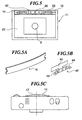
- the holder best shown in Figs. 5 and 5A, is inserted and fixed by a snap fit over the open end (photographic film side) of the character exposure section 14.
- Character film 13 is attached to the film holder 16 by bonding or by sliding into a slot (not shown) formed at the open end of the character exposure section 14.
- the surface of character film 13 contacts the film surface 19 of the photographic film to prevent gaps that could permit light generated by the character strobe 25 to stray into the area of the film frame 17 that is exposed by the subject exposure chamber section 23.
- the contour of the exposure chamber provides a convex profile to the film frame 17 to help provide a zero-gap surface interface with the film 26 that is extended over the chamber as is shown in Fig. 5C.
- the artificial light generating source may comprise an electric light bulb or LED.
- an identical strobe flash bulb to that used for the subject flash 4 is preferably used, thereby reducing the number of separate components needed to assemble the camera.
- the character flash need not be of as high intensity as the subject flash, its intensity may be reduced, electrically by use of resistors (described later herein) or by shading.
- a light shade 42 for reducing the intensity of the character strobe flash 25 is shown in FIGS. 5 and 4, 5B. Though various mechanisms for shading the light produced by the strobe are possible, the shade shown in the figures is fabricated from a thin metal material.
- the light shade shown includes a convex shaded portion 44 and a reflector portion 46 that are integrally formed as one piece.
- the light shade can be mounted in the character exposure chamber 14, adhered to the light shield 15, with the character flash 25 located behind it by supports 50 integrally formed with the light shield.
- the shade portion 44 is positioned between the character strobe and the character film and is perforated with several holes 48 that permit a reduced amount of light to pass from the character flash to the character film holder 16 and associated film 13 to be exposed onto the film frame 17.
- the convex shape of the shade presented to the light generating source 25 is believed to help reduce the light intensity.
- the reflector portion 46 of the light shade resides between the front wall 38 and character flash 25 to reflect light transmitted to the front of the camera back forward the character film 13 and photographic film frame 17.
- other types of light shades may be used including types that are not of a completely opaque material, but that provide a transparent but shaded barrier such as a darkened strip of film.
- Figure 6 is a diagram of an exemplary shared electrical circuit for the subject and character flashes.
- the circuit includes power source battery B, power source switch SW1 linked with slide button 5, transistor Tr, resistor R, rectifier D, capacitor C, neon lamp N and choke CH for the trigger.
- Switch SW2 is joined to the shutter and is configured to turn ON when the shutter 12 is in the fully open position (a picture is taken) simultaneously energizing the subject strobe flash 4 which illuminates the subject, and the character strobe flash 25 which exposes the character film.
- the character flash can be operated on a separate circuit from that of the subject flash so that either flash can be energized independently of the other.
- a diagram of a shared circuit is shown for illustration, as this configuration requires the least number of components and is most cost effective, which is an object of the invention.
- the shutter 12 When the user depresses a release button (not shown), the shutter 12 begins to open and the subject (or image) begins to expose the frame of photographic film 17 via camera lens 2. At the fully open position of the shutter 12, a part of the shutter pushes the switch SW2 to the ON position.
- the high voltage current which had charged capacitor C1, flows through trigger choke CH.
- a high voltage is instantaneously generated, triggering strobe flashes 4 and 25, whereupon the electrode in strobe flashes 4 and 25 discharge, causing the strobes to flash.
- the emission from strobe flash 4 illuminates the subject.
- the emission from strobe flash 25 directly illuminates the character film 13, and exposes the photographic film frame 17 in contact with it.
- the current flowing to the strobe 25 can be reduced and the light intensity thus limited to a suitably low level by inserting resistor R4 serially. Additionally, by including resistor R4, the drop in light intensity of external strobe flash 4 due to the power drain caused by flash 25 connected to it in parallel, is minimized. As discussed above, a light shade alternatively, or additionally may be placed between the flash 25 and film frame 17 to reduce the light intensity.
- Fig. 7 is an example of a photographic print 61 made from the camera of the present invention.
- the subject area 64 appears in the upper portion of the print 61.
- Character area 62 appears in the lower part of the print 61.
- a record regarding the subject of the print also can be entered, written with a ballpoint pen for example, in the margin 63 of the character area 62.
- the entire character area 62 of the frame 61 can be made available for a written record on the finished print by omitting characters from the character film 13 during exposure of the film frames.
- the frame 61 can be brightened, if needed, by making an adjustment for the exposure level during the printing stage of the print process. For example, when the subject is dark, such as occurs in night scenery or indoor photography, the subject can be brightened.
- the frame 61 can also be dimmed by making an adjustment at the printing stage of the print process when the screen is too bright, such as occurs during photography under bright sunlight.
- the character area 62 which always has a constant exposure due to its independent and artificial light generating source, can be adversely affected because printing technology requires that the entire frame be adjusted as together.
- One exposure frame cannot be adjusted for two brightness levels. Thus the character area can be made too light, if the exposure had been increased to compensate for a dark subject, while character area 62 can be made too dark if the exposure had been decreased to compensate for a bright subject.
- Fig. 8 relates to a second embodiment of the present invention that provides a countermeasure to the above described problem.
- the character flash emission circuitry shown in Fig. 8 is arranged so that it can be switched between multiple serial resistors by using a switch SW3 to vary the intensity of the character flash to coincide with the light conditions of the subject.
- An exterior slide knob (not shown) can be employed on the exterior of the camera body 22 to manipulate the switch SW-3.
- Resistor RH with high resistance and resistor RL with low resistance regulates differently the power delivered to the flash 25, causing the flash to operate at different intensity levels.
- the arrangement of all other components shown in Fig. 8, is the same as was described in connection with Fig. 6.
- the exposure adjustment at the printing stage is thus kept from affecting the character area 62 of the frame 61 by switching the resistor to the RH side when the subject is dark, such as occurs in night scenery or indoor photography so that the character area can be brightened the appropriate amount along with the subject area of the frame during the print process.
- the character area 62 of the print will be compensated to be darker along with the subject area 64 of the print during printing.
- a slide knob 81 manipulates switch SW-3.
- the exposure adjustment at the printing stage is kept from affecting the character by switching the slide knob 81 to the RH side when the subject is dark, such as occurs in night scenery or indoor photography, and by switching the slide knob 81 to the RL side when the subject is bright, such as occurs in photography under daytime sunlight.
- Exposing the character film directly with a strobe flash light as opposed to introducing light by an optical conductor, such as optical fiber, offers several advantages. Cost is reduced since little additional electrical hardware is necessary to power the character flash 25, some of which can be shared with the subject strobe flash emission circuitry. In addition, since the flash emitted from a thin strobe flash bulb itself is a thin and long light, the desired character area shape of a long rectangular shape in the exposure frame 17 can be illuminated uniformly along its length both easily and inexpensively in comparison to adding a light diffusor as is required by the optical fiber to produce a character image of long rectangular shape.
- the cost of manufacture can be lowered considerably compared to the cost for conventional methods of drawing around an optical conductor, such as optical fiber, since only electrical wiring would be necessary, and it can share much of the strobe flash emission circuitry for illuminating the subject.
- the character image of long rectangular shape can be illuminated uniformly along its length both easily and inexpensively for a character image of long rectangular shape.
- the flash of a direct strobe flash tube is used as a character light source, there is no nuisance associated with color temperature correction of the character film, since the color temperature of the strobe flash light and noon-light color film is approximately the same. For example, there is far less difficulty compared with the case where an incandescent bulb is employed as the character light source.
Landscapes
- Physics & Mathematics (AREA)
- General Physics & Mathematics (AREA)
- Stroboscope Apparatuses (AREA)
Applications Claiming Priority (4)
| Application Number | Priority Date | Filing Date | Title |
|---|---|---|---|
| US87299497A | 1997-06-11 | 1997-06-11 | |
| US872994 | 1997-06-11 | ||
| US94793297A | 1997-10-09 | 1997-10-09 | |
| US947932 | 1997-10-09 |
Publications (1)
| Publication Number | Publication Date |
|---|---|
| EP0884629A1 true EP0884629A1 (de) | 1998-12-16 |
Family
ID=27128272
Family Applications (1)
| Application Number | Title | Priority Date | Filing Date |
|---|---|---|---|
| EP97117587A Withdrawn EP0884629A1 (de) | 1997-06-11 | 1997-10-10 | Kamera versehen mit einer Zeichen-Anzeigevorrichtung |
Country Status (1)
| Country | Link |
|---|---|
| EP (1) | EP0884629A1 (de) |
Cited By (1)
| Publication number | Priority date | Publication date | Assignee | Title |
|---|---|---|---|---|
| US6707959B2 (en) | 2001-07-12 | 2004-03-16 | Jds Uniphase Inc. | Wavelength switch |
Citations (6)
| Publication number | Priority date | Publication date | Assignee | Title |
|---|---|---|---|---|
| DE1016552B (de) * | 1954-08-26 | 1957-09-26 | Zeiss Carl Fa | Einrichtung zum Belichten von Hilfsabbildungen, insbesondere bei Luftbildkameras |
| DE2112409A1 (de) * | 1971-03-15 | 1972-09-21 | Edwin Kellenberger | Einrichtung zur Beschriftung von photographischen Negativen |
| US4174165A (en) * | 1977-04-29 | 1979-11-13 | Minolta Camera Kabushiki Kaisha | Power supply control device for cameras |
| US4497552A (en) * | 1981-08-05 | 1985-02-05 | Howard Lowell C | Data recording system for cameras |
| WO1993003412A1 (en) * | 1991-08-07 | 1993-02-18 | Concord Camera Corporation | Symbol imprinting mechanism for cameras |
| US5521665A (en) * | 1995-01-03 | 1996-05-28 | Eastman Kodak Company | Composite image camera with flash device |
-
1997
- 1997-10-10 EP EP97117587A patent/EP0884629A1/de not_active Withdrawn
Patent Citations (6)
| Publication number | Priority date | Publication date | Assignee | Title |
|---|---|---|---|---|
| DE1016552B (de) * | 1954-08-26 | 1957-09-26 | Zeiss Carl Fa | Einrichtung zum Belichten von Hilfsabbildungen, insbesondere bei Luftbildkameras |
| DE2112409A1 (de) * | 1971-03-15 | 1972-09-21 | Edwin Kellenberger | Einrichtung zur Beschriftung von photographischen Negativen |
| US4174165A (en) * | 1977-04-29 | 1979-11-13 | Minolta Camera Kabushiki Kaisha | Power supply control device for cameras |
| US4497552A (en) * | 1981-08-05 | 1985-02-05 | Howard Lowell C | Data recording system for cameras |
| WO1993003412A1 (en) * | 1991-08-07 | 1993-02-18 | Concord Camera Corporation | Symbol imprinting mechanism for cameras |
| US5521665A (en) * | 1995-01-03 | 1996-05-28 | Eastman Kodak Company | Composite image camera with flash device |
Cited By (1)
| Publication number | Priority date | Publication date | Assignee | Title |
|---|---|---|---|---|
| US6707959B2 (en) | 2001-07-12 | 2004-03-16 | Jds Uniphase Inc. | Wavelength switch |
Similar Documents
| Publication | Publication Date | Title |
|---|---|---|
| US6249652B1 (en) | Lens-fitted photo film unit and method of producing photographic print | |
| US5546146A (en) | Single use camera film pre-exposure method | |
| JPH0141971B2 (de) | ||
| US5784658A (en) | Optical data recording device of camera and lens-fitted photographic film unit | |
| US4894671A (en) | Film pack support of image-bearing template | |
| US4402588A (en) | Automatic photograph labeler employing camera with passive display | |
| EP0884629A1 (de) | Kamera versehen mit einer Zeichen-Anzeigevorrichtung | |
| US5471268A (en) | Character imprinting device for a camera | |
| JPS5945971B2 (ja) | デ−タ写し込み装置 | |
| JP2007034172A (ja) | ストロボ減光板及びストロボ装置並びにレンズ付きフイルムユニット | |
| JPH09281584A (ja) | キャラクタ表示装置を備えたカメラ | |
| JP3471116B2 (ja) | レンズ付きフイルムユニット用プレ露光装置 | |
| JP3922500B2 (ja) | レンズ付きフイルムユニット | |
| JP3064031U (ja) | カメラ用デバイスおよびカメラ | |
| JP3710269B2 (ja) | レンズ付きフイルムユニット | |
| JPS6120581Y2 (de) | ||
| US5890023A (en) | Apparatus for providing fogged write-on borders on film frame in camera | |
| JPS6235076Y2 (de) | ||
| JPH082664Y2 (ja) | フィルム一体型カメラ | |
| JP2000284347A (ja) | ストロボ装置 | |
| US6035129A (en) | Optical film encoder for camera | |
| JP2002122912A (ja) | カメラの閃光照射角確認装置 | |
| EP0550884A1 (de) | Kamera mit wählbarem Bildformat | |
| JPH1124211A (ja) | レンズ付きフイルムユニット用プレ露光方法及び装置 | |
| JPH03131833A (ja) | カメラのデータ写し込み装置 |
Legal Events
| Date | Code | Title | Description |
|---|---|---|---|
| PUAI | Public reference made under article 153(3) epc to a published international application that has entered the european phase |
Free format text: ORIGINAL CODE: 0009012 |
|
| AK | Designated contracting states |
Kind code of ref document: A1 Designated state(s): ES FR GB IT |
|
| AX | Request for extension of the european patent |
Free format text: AL;LT;LV;RO;SI |
|
| 17P | Request for examination filed |
Effective date: 19990416 |
|
| AKX | Designation fees paid |
Free format text: ES FR GB IT |
|
| REG | Reference to a national code |
Ref country code: DE Ref legal event code: 8566 |
|
| STAA | Information on the status of an ep patent application or granted ep patent |
Free format text: STATUS: THE APPLICATION IS DEEMED TO BE WITHDRAWN |
|
| 18D | Application deemed to be withdrawn |
Effective date: 20010501 |