EP0884774A2 - Verfahren zur Herstellung eines Halbleiterbauelements mit einem Isolationsgraben - Google Patents
Verfahren zur Herstellung eines Halbleiterbauelements mit einem Isolationsgraben Download PDFInfo
- Publication number
- EP0884774A2 EP0884774A2 EP98109987A EP98109987A EP0884774A2 EP 0884774 A2 EP0884774 A2 EP 0884774A2 EP 98109987 A EP98109987 A EP 98109987A EP 98109987 A EP98109987 A EP 98109987A EP 0884774 A2 EP0884774 A2 EP 0884774A2
- Authority
- EP
- European Patent Office
- Prior art keywords
- photoresist pattern
- region
- trench
- principal surface
- insulating film
- Prior art date
- Legal status (The legal status is an assumption and is not a legal conclusion. Google has not performed a legal analysis and makes no representation as to the accuracy of the status listed.)
- Withdrawn
Links
Images


Classifications
-
- H—ELECTRICITY
- H10—SEMICONDUCTOR DEVICES; ELECTRIC SOLID-STATE DEVICES NOT OTHERWISE PROVIDED FOR
- H10W—GENERIC PACKAGES, INTERCONNECTIONS, CONNECTORS OR OTHER CONSTRUCTIONAL DETAILS OF DEVICES COVERED BY CLASS H10
- H10W10/00—Isolation regions in semiconductor bodies between components of integrated devices
- H10W10/01—Manufacture or treatment
- H10W10/011—Manufacture or treatment of isolation regions comprising dielectric materials
- H10W10/014—Manufacture or treatment of isolation regions comprising dielectric materials using trench refilling with dielectric materials, e.g. shallow trench isolations
- H10W10/0145—Manufacture or treatment of isolation regions comprising dielectric materials using trench refilling with dielectric materials, e.g. shallow trench isolations of trenches having shapes other than rectangular or V-shape
-
- H—ELECTRICITY
- H10—SEMICONDUCTOR DEVICES; ELECTRIC SOLID-STATE DEVICES NOT OTHERWISE PROVIDED FOR
- H10W—GENERIC PACKAGES, INTERCONNECTIONS, CONNECTORS OR OTHER CONSTRUCTIONAL DETAILS OF DEVICES COVERED BY CLASS H10
- H10W10/00—Isolation regions in semiconductor bodies between components of integrated devices
- H10W10/10—Isolation regions comprising dielectric materials
- H10W10/17—Isolation regions comprising dielectric materials formed using trench refilling with dielectric materials, e.g. shallow trench isolations
Definitions
- the present invention relates to a method for manufacturing a semiconductor device, and more specifically to a method for manufacturing a semiconductor device such as a MOSFET integrated circuit having trenches having different depths.
- microminiaturization of circuit elements With recent increase in the integration density of a semiconductor integrated circuit, further microminiaturization of circuit elements is demanded. In addition, with the microminiaturization of circuit elements, microminiaturization of a device isolation region is demanded and has become an important problem.
- Japanese Patent Application Pre-examination Publication No. JP-A-60-226126 and No. JP-A-01-232739 propose semiconductor device manufacturing methods using a device isolation technology utilizing the trench. In these methods, each device is isolated by forming trenches having different depths. In addition, it is necessary to carry out a different photoresist process for each trench having a different depth.
- an English abstract of each of JP-A-60-226126 and No. JP-A-01-232739 is available from the Japanese Patent Office and the content of each English abstract is also incorporated by reference in its entirety into this application.
- JP-A-60-226126 After a mask pattern for forming a shallow trench is formed, a photoresist is formed to cover a deep trench formation region and then patterned, and a mask layer is etched by using the patterned photoresist as a mask to form a deep trench, and thereafter, a further etching is conducted by using the mask pattern for forming the shallow trench, so as to form a shallow trench.
- the prior art method typified by the process disclosed by JP-A-60-226126 requires two photoresist processes, namely, a photoresist process for forming the shallow trench and a photoresist process for forming the deep trench.
- Increase of the number of photoresist processes results in increase of the number of photoresist removing processes, resulting in an increased cost for manufacturing the semiconductor device.
- JP-A-60-226135 (an English abstract of JP-A-60-226135 is available from the Japanese Patent Office and the content of the English abstract of JP-A-60-226135 is incorporated by reference in its entirety into this application) proposed a semiconductor device manufacturing method capable of simplifying the process for forming the trench for the device isolation.
- a pattern for forming a deep trench used for a well isolation is automatically generated in a self-alignment with a well pattern.
- a gap is formed in a self alignment at an end of the mask pattern used for a well implantation, by a lift-off process, and then, an etching is carried out to form a trench.
- the deep trench used for the well isolation can be formed without increasing the number of photoresist steps.
- a mask used for forming the trench having a sufficient depth to penetrate through the well in order to isolate the well is formed by lifting off a plasma CVD insulating film on a first mask formed on a first well, by utilizing the phenomenon that a side wall of the plasma CVD insulating film is preferentially etched.
- the plasma CVD insulating film no longer enters into the gaps between the first masks, with the result that a mask used for forming a trench in a second well by an etching cannot be formed.
- a second problem is that, when the plasma CVD insulating film is lifted off, the peeled-off plasma CVD film is deposited again on the semiconductor substrate, with the stability in manufacturing of the semiconductor integrated circuit device is obstructed.
- Another object of the present invention is to provide a semiconductor device forming method, capable of forming a trench for a device isolation, without increasing the number of photoresist steps.
- Still another object of the present invention is to provide a semiconductor device forming method, capable of stably forming a trench for a device isolation, even in a reduced device size, without increasing the number of photoresist steps, and without obstructing the stability in manufacturing of the semiconductor integrated circuit device.
- a method for manufacturing a semiconductor device including the steps of forming a well in a semiconductor substrate by using a first photoresist pattern as a mask, and patterning an insulating film formed on the semiconductor substrate, by using the first photoresist pattern as a mask, and forming a trench in the semiconductor substrate by using as a mask the patterned insulating film and a second photoresist pattern formed separately from the patterned insulating film.
- a method for manufacturing a semiconductor device including the steps of forming a first insulating film on a semiconductor substrate, patterned by using a first photoresist pattern used for forming a first well, forming a second insulating film on the semiconductor substrate, patterned by using a second photoresist pattern used for forming a second well near to the first well, and forming a trench in the semiconductor substrate by using the first and second insulating films as a mask.
- a trench structure is formed for a well isolation or a device isolation.
- the trench is formed in self-alignment with a well pattern, without using the lift-off technology as in the prior art disclosed by the JP-A-60-226135.
- the general prior art semiconductor device forming method when a deep trench and a shallow trench are formed in the semiconductor device, it was required to carry out a plurality of photoresist steps while performing an alignment for formation of each trench.
- the trench is formed by using, as a mask, a photoresist used for a well formation, and a silicon-based film such as a silicon oxide film and a polysilicon film which are formed on a silicon semiconductor substrate and patterned by an etching using the photoresist used for the well formation. Therefore, it is no longer necessary to add a photoresist step for the purpose of forming the device isolating trench, and therefore, it is no longer necessary to perform an alignment for patterning a photoresist for formation of the device isolating trench. Furthermore, since the number of photoresist steps is not increased, the manufacturing cost can be suppressed.
- the trench can be surely formed.
- the lift-off is not carried out, there occurs no problem in which the peeled-off plasma CVD insulating film is deposited on the semiconductor substrate again.
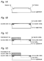
- trenches 102 having the depth of 300nm are formed in a principal surface of a substrate 101 formed of a single crystalline silicon of a first conductivity type.
- a substrate 101 formed of a single crystalline silicon of a first conductivity type.
- a silicon oxide 103 is filled into the trenches 102, and a silicon oxide layer 104 having the thickness of 10nm is formed to cover the filling silicon oxide 103 and the principal surface of the substrate 101.
- the trenches 102 are filled up by depositing a silicon oxide by means of a CVD (chemical vapor deposition) process and then planarizing the deposited silicon oxide by a CMP (chemical mechanical polishing) process.
- CVD chemical vapor deposition
- CMP chemical mechanical polishing
- a patterned photoresist 105 is formed to cover only a P-well forming region which is to be formed in a later step. Furthermore, a donor such as phosphorus is ion-implanted at a dose of 5 ⁇ 10 15 cm -2 under 1000keV, at a dose of 5 ⁇ 10 15 cm -2 under 500keV, and then, at a dose of 5 ⁇ 10 15 cm -2 under 100keV, to form an N-well 106. Within this N-well 106, a pMOSFET will be formed in a later step (not shown).
- the exposed silicon oxide film 104 on the N-well 106 is removed by a selective etching using fluorine, using the photoresist 105 as a mask.
- a photoresist 107 is formed to cover a portion of the N-well 106.
- This photoresist 107 is formed in such a manner that an end of the photoresist 107 is separated from an end "A" of the N-well 106 by a predetermined distance (for example, on the order of 0.5 ⁇ m). This predetermined distance will determine the width of a trench which will be formed in a later step.
- a P-well 108 is formed by an ion implantation.
- an acceptor such as boron is ion-implanted at a dose of 5 ⁇ 10 15 cm -2 under 500keV, and then at a dose of 5 ⁇ 10 15 cm -2 under 250keV.
- an nMOSFET will be formed in a later step (not shown).
- the substrate 101 is etched using the photoresist 107 and the remaining silicon oxide film 104 as a mask, to form a trench 109 having the depth of about 500nm, which is larger than that of the firstly formed trench 102.
- the photoresist 107 is removed, and as shown in Fig. 1H, an insulating material such as a silicon oxide 110 is filled into the deep trench 109.
- an insulating material such as a silicon oxide 110 is filled into the deep trench 109.
- the photoresist 107 is formed directly on an exposed region of the substrate 101 in the step shown in Fig. 1E.
- the process including the step exposing the substrate surface to the photoresist such as the step shown in Fig. 1E, there is a fear that the substrate 101 is contaminated with impurity.
- a method for forming a trench without exposing the substrate surface directly to the photoresist will be described as a second embodiment.
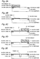
- the N-well 106 is formed in the substrate 101 and the silicon oxide film 104 on the N-well 106 is selectively removed, similarly to the steps of the first embodiment until the step shown in Fig. 1D.
- a silicon oxide film 111 having the thickness of 10nm is formed by a thermal oxidation to cover the whole surface as shown in Fig. 2B.
- a silicon oxide film having a thickness of about 20nm is composed of the silicon oxide films 104 and 111.
- another photoresist 107 is formed to cover a portion of the N-well 106 in such a manner that an end of the photoresist 107 is separated from an end "A" of the N-well 106 by a predetermined distance corresponding to the width of a trench which will be formed in a later step.
- a P-well 108 is formed by ion-implanting an acceptor such as boron, similarly to the first embodiment, and then, the silicon oxide film 111 is selectively removed by fluorine, using the photoresist 107 as a mask, so that an exposed region of the substrate 101 is formed between the end "A" of the N-well 106 and the end of the photoresist 107.
- the substrate 101 is etched using the photoresist 107 and the remaining silicon oxide film 104 as a mask, to form a deep trench 109, similarly to the first embodiment. Further, the photoresist 107 is removed, and an insulating material is filled into the deep trench 109, also similarly to the first embodiment.
- first and second embodiments only the deep trench 109 is formed in the device isolation region.
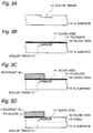
- a method for forming a plurality of trenches having different depths in the isolation region will be described with reference to Figs. 3A to 3H.
- a shallow trench 112 is formed in a principal surface of a substrate 101 formed of a single crystalline silicon.
- a silicon oxide layer 104 having the thickness of 10nm is formed to cover the whole surface while filling up the shallow trench 112 with a silicon oxide 114.
- This can be realized by depositing a silicon oxide by a CVD process and then by planarizing the deposited silicon oxide by a CMP process.
- a polysilicon film 113 is formed on a surface of the silicon oxide film 104.
- a patterned photoresist 105 is formed on the polysilicon film 113 to cover only a P-well forming region which is to be formed in a later step, and in such a manner that the photoresist 105 partially covers the silicon oxide 114 filled up into the shallow trench 112.
- the polysilicon film 113 is selectively removed by an etching using the photoresist 105 as a mask, and as shown in Fig. 3D, the N-well 106 is formed, similarly to the process described in connection with the first embodiment.
- another photoresist 107 is formed to cover a portion of the N-well 106 in such a manner that an end of the photoresist 107 is separated from an end "A" of the N-well 106 by a predetermined distance corresponding to the width of a deep trench which will be formed in a later step, so that a spacing between the end "A" of the N-well 106 and the above mentioned end of the photoresist 107 is positioned at a center of the shallow trench 112.
- the silicon oxide film 104 and the silicon oxide 114 filling up the shallow trench 112 is selectively removed by an etching using the remaining polysilicon layer 113 and the photoresist 107 as a mask, so that the silicon substrate is exposed at the center of the shallow trench 112.
- the remaining polysilicon layer 113 is removed by an etching, and at the same time, the silicon substrate 101 is further etched by a depth on the order of 10nm at a position where the silicon substrate is exposed at the center of the shallow trench 112.
- a P-well 108 is formed, similarly to the first embodiment.
- the substrate 101 is further etched using the photoresist 107 and the exposed silicon oxide film 104 as a mask, to form a deep trench 109 which is deeper than the depth of the N-well 106 and the P-well 108.
- the photoresist 107 is removed, and as shown in Fig. 3J, an insulating material such as a silicon oxide 110 is filled into the deep trench 109.
- an insulating material such as a silicon oxide 110 is filled into the deep trench 109.
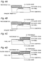
- a shallow trench 112 is formed in a principal surface of the substrate 101, and a silicon oxide film 104 having the thickness of 10nm is formed on the principal surface of the substrate 101, while filling up the shallow trench 112 with a silicon oxide 114.
- a patterned photoresist 105 is formed to partially cover the silicon oxide film 104 in such a manner that patterned photoresist 105 covers a more-than-half portion of a surface of the silicon oxide 114 filling up the shallow trench 112, including a center of the silicon oxide 114 filling up the shallow trench 112.
- an N-well 106 is formed by an ion implantation using the photoresist 105 as a mask.
- the silicon oxide film 115 can be selectively formed on the region excluding the photoresist 105, by for example, immersing the substrate 101 into an aqueous solution of hydrosilicofluoric acid (H 2 SiF 6 ), and causing a boric acid (H 3 BO 3 ) aqueous solution to fall in drops into the aqueous solution of hydrosilicofluoric acid.
- the photoresist 105 on the P-well forming region is selectively removed, and another photoresist 107 is formed on the silicon oxide film 115.
- a P-well 108 is formed, similarly to the process of the first embodiment.
- a silicon oxide film 116 having a thickness equal to that of the silicon oxide film 115 is selectively formed only on the silicon oxide film 104 under which the P-well region 108 is formed.
- etching is carried out until the silicon oxide film 114 filling up the shallow trench 112 is removed and the bottom of the shallow trench 112 is exposed, as shown in Fig. 4F.
- the substrate 101 is etched using the remaining silicon oxide films 115 and 116 as a mask, to form a deep trench 109 which is deeper than the depth of the N-well 106 and the P-well 108.
- an insulating material such as a silicon oxide 110 is filled into the deep trench 109.
- the semiconductor device which has the well isolation region in which the deep trench 109 is formed and a pair of shallow trenches are formed at opposite sides of the deep trench 109, and these trenches 109 and 112 are filled up with the silicon oxides 110 and 114.
- a process for filling up the deep trench with an insulating material in the first to fourth embodiments can include the step of depositing an insulating material by a CVD process and the step of removing the deposited insulating material to the substrate surface by means of the CMP process.
- a silicon oxide film 117 having the thickness of 10nm is formed on an inner wall surface of the trench 109 and the surface of the substrate 101 (N-well 106 and P-well 108).
- a silicon nitride film 118 is formed on the surface of the silicon oxide film 117.
- a silicon oxide film 119 is deposited on the silicon nitride film 118 by the CVD process to completely fill up the deep trench 109.
- the silicon oxide film 119 is polished by the CMP process.
- the CMP process since the polishing of the silicon nitride 118 is more difficult than the polishing of the silicon oxide film, if the polishing reaches the silicon nitride film 118, the polishing speed drops. Therefore, at this time where the polishing reaches the silicon nitride film 118, the CMP process is stopped.
- the silicon oxide film 119 on the substrate surface can be surely removed with a high degree of polishing precision.
- the exposed silicon nitride film 118 is removed by a heated phosphoric acid.
- the deep trench filled up with the insulating material is formed as shown in Fig. 5E.
- the semiconductor device forming method in accordance with the present invention has the following advantages: Namely, since the pattern for forming a deep trench for the well isolation is automatically set from the positional relation between one well and a mask for forming another well, it is no longer necessary to add a photoresist step for forming a trench formation pattern. In addition, since the lift-off process used in the prior art is not used in the semiconductor device forming method in accordance with the present invention, it is possible to form an isolation trench having a narrow width, and also, there does not occur the re-deposition of the peeled-off plasma CVD insulating film onto the semiconductor substrate, with the result that the stability in manufacturing the semiconductor device is remarkably elevated.
Landscapes
- Element Separation (AREA)
Applications Claiming Priority (3)
| Application Number | Priority Date | Filing Date | Title |
|---|---|---|---|
| JP9141393A JP3050166B2 (ja) | 1997-05-30 | 1997-05-30 | 半導体装置の製造方法 |
| JP141393/97 | 1997-05-30 | ||
| JP14139397 | 1997-05-30 |
Publications (2)
| Publication Number | Publication Date |
|---|---|
| EP0884774A2 true EP0884774A2 (de) | 1998-12-16 |
| EP0884774A3 EP0884774A3 (de) | 2000-03-15 |
Family
ID=15290955
Family Applications (1)
| Application Number | Title | Priority Date | Filing Date |
|---|---|---|---|
| EP98109987A Withdrawn EP0884774A3 (de) | 1997-05-30 | 1998-06-02 | Verfahren zur Herstellung eines Halbleiterbauelements mit einem Isolationsgraben |
Country Status (5)
| Country | Link |
|---|---|
| US (1) | US5937286A (de) |
| EP (1) | EP0884774A3 (de) |
| JP (1) | JP3050166B2 (de) |
| KR (1) | KR100318640B1 (de) |
| CN (1) | CN1203448A (de) |
Cited By (1)
| Publication number | Priority date | Publication date | Assignee | Title |
|---|---|---|---|---|
| DE10311059A1 (de) * | 2003-03-13 | 2004-10-07 | Infineon Technologies Ag | Halbleiterstruktur |
Families Citing this family (17)
| Publication number | Priority date | Publication date | Assignee | Title |
|---|---|---|---|---|
| US6579738B2 (en) * | 2000-12-15 | 2003-06-17 | Micron Technology, Inc. | Method of alignment for buried structures formed by surface transformation of empty spaces in solid state materials |
| KR20020056288A (ko) * | 2000-12-29 | 2002-07-10 | 박종섭 | 반도체 장치의 셜로우 트랜치 아이솔레이션 형성방법 |
| KR100390903B1 (ko) * | 2000-12-29 | 2003-07-12 | 주식회사 하이닉스반도체 | 반도체 장치의 에스램 셀 제조방법 |
| US6599813B2 (en) | 2001-06-29 | 2003-07-29 | International Business Machines Corporation | Method of forming shallow trench isolation for thin silicon-on-insulator substrates |
| JP3921363B2 (ja) * | 2001-08-20 | 2007-05-30 | 松下電器産業株式会社 | 不揮発性半導体記憶装置の製造方法 |
| KR100400254B1 (ko) | 2001-12-18 | 2003-10-01 | 주식회사 하이닉스반도체 | 반도체 소자의 제조방법 |
| KR100974421B1 (ko) | 2003-04-04 | 2010-08-05 | 매그나칩 반도체 유한회사 | 반도체 소자의 디자인 룰 개선방법 |
| KR100525797B1 (ko) * | 2003-06-18 | 2005-11-02 | 동부아남반도체 주식회사 | 소자분리막 구조 및 제조 방법 |
| KR100561519B1 (ko) * | 2003-12-30 | 2006-03-17 | 동부아남반도체 주식회사 | 반도체 제조 공정에 있어서의 웰 형성 방법 |
| US20070158779A1 (en) * | 2006-01-12 | 2007-07-12 | International Business Machines Corporation | Methods and semiconductor structures for latch-up suppression using a buried damage layer |
| US7648869B2 (en) * | 2006-01-12 | 2010-01-19 | International Business Machines Corporation | Method of fabricating semiconductor structures for latch-up suppression |
| US7276768B2 (en) * | 2006-01-26 | 2007-10-02 | International Business Machines Corporation | Semiconductor structures for latch-up suppression and methods of forming such semiconductor structures |
| US7491618B2 (en) * | 2006-01-26 | 2009-02-17 | International Business Machines Corporation | Methods and semiconductor structures for latch-up suppression using a conductive region |
| US20070194403A1 (en) * | 2006-02-23 | 2007-08-23 | International Business Machines Corporation | Methods for fabricating semiconductor device structures with reduced susceptibility to latch-up and semiconductor device structures formed by the methods |
| US7818702B2 (en) * | 2007-02-28 | 2010-10-19 | International Business Machines Corporation | Structure incorporating latch-up resistant semiconductor device structures on hybrid substrates |
| US7754513B2 (en) * | 2007-02-28 | 2010-07-13 | International Business Machines Corporation | Latch-up resistant semiconductor structures on hybrid substrates and methods for forming such semiconductor structures |
| US9312143B1 (en) * | 2014-11-24 | 2016-04-12 | International Business Machines Corporation | Formation of isolation surrounding well implantation |
Family Cites Families (8)
| Publication number | Priority date | Publication date | Assignee | Title |
|---|---|---|---|---|
| JPS60226136A (ja) * | 1984-04-25 | 1985-11-11 | Hitachi Ltd | 相補型金属絶縁物半導体装置およびその製法 |
| JPS60226135A (ja) * | 1984-04-25 | 1985-11-11 | Hitachi Ltd | 半導体装置の製造方法 |
| JPS62277745A (ja) * | 1986-05-27 | 1987-12-02 | Toshiba Corp | 半導体集積回路 |
| JPH01232739A (ja) * | 1988-03-12 | 1989-09-18 | Ricoh Co Ltd | 半導体装置の製造方法 |
| US4876214A (en) * | 1988-06-02 | 1989-10-24 | Tektronix, Inc. | Method for fabricating an isolation region in a semiconductor substrate |
| US5449367A (en) * | 1993-08-02 | 1995-09-12 | Kadry; Othman | Pre-tied knot for surgical use and method of using same |
| US5536675A (en) * | 1993-12-30 | 1996-07-16 | Intel Corporation | Isolation structure formation for semiconductor circuit fabrication |
| JP3331798B2 (ja) * | 1995-01-26 | 2002-10-07 | ソニー株式会社 | 不純物層の分離領域形成方法 |
-
1997
- 1997-05-30 JP JP9141393A patent/JP3050166B2/ja not_active Expired - Lifetime
-
1998
- 1998-05-29 KR KR1019980019931A patent/KR100318640B1/ko not_active Expired - Fee Related
- 1998-05-29 CN CN98102308A patent/CN1203448A/zh active Pending
- 1998-06-01 US US09/088,072 patent/US5937286A/en not_active Expired - Fee Related
- 1998-06-02 EP EP98109987A patent/EP0884774A3/de not_active Withdrawn
Cited By (1)
| Publication number | Priority date | Publication date | Assignee | Title |
|---|---|---|---|---|
| DE10311059A1 (de) * | 2003-03-13 | 2004-10-07 | Infineon Technologies Ag | Halbleiterstruktur |
Also Published As
| Publication number | Publication date |
|---|---|
| US5937286A (en) | 1999-08-10 |
| KR100318640B1 (ko) | 2002-04-22 |
| JPH10335441A (ja) | 1998-12-18 |
| JP3050166B2 (ja) | 2000-06-12 |
| CN1203448A (zh) | 1998-12-30 |
| EP0884774A3 (de) | 2000-03-15 |
Similar Documents
| Publication | Publication Date | Title |
|---|---|---|
| US5937286A (en) | Method for manufacturing semiconductor device | |
| US6093621A (en) | Method of forming shallow trench isolation | |
| EP1213757B1 (de) | Integrierte Schaltkreise und benachbarte p-dotierte Gebiete mit flachen Grabenisolations-Strukturen ohne "Liner"-Schichten dazwischen und zugehöriges Herstellungsverfahren | |
| KR100252751B1 (ko) | 반도체 소자 제조 방법 | |
| US5677232A (en) | Methods of fabricating combined field oxide/trench isolation regions | |
| US6720667B2 (en) | Semiconductor device having align key for defining active region and method for manufacturing the same | |
| KR20030069776A (ko) | 반도체장치의 제조방법 | |
| KR100596876B1 (ko) | 반도체 소자의 소자 분리막 형성 방법 | |
| KR100979711B1 (ko) | 반도체장치의 트렌치 갭필 방법 | |
| KR19980027682A (ko) | 반도체 기판 및 그 제조 방법 | |
| KR100289663B1 (ko) | 반도체 소자의 소자 분리막 형성방법 | |
| US6319795B1 (en) | Method for fabricating VLSI devices having trench isolation regions | |
| US6287937B1 (en) | Method for simultaneous dopant driving and dielectric densification in making a semiconductor structure | |
| JPH0729971A (ja) | 半導体装置の製造方法 | |
| KR100242526B1 (ko) | 반도체장치의 소자격리방법 | |
| JP3331798B2 (ja) | 不純物層の分離領域形成方法 | |
| KR0180134B1 (ko) | 트윈 웰 형성 방법 | |
| KR0161727B1 (ko) | 반도체 소자의 소자분리방법 | |
| KR100249023B1 (ko) | 반도체장치의 소자격리방법 | |
| KR100215698B1 (ko) | 반도체 소자의 소자 분리막 형성 방법 | |
| KR0172760B1 (ko) | 반도체 소자의 소자 분리 절연막 제조 방법 | |
| JPH0410746B2 (de) | ||
| KR100203897B1 (ko) | 반도체 소자의 소자분리막 제조방법 | |
| KR970009273B1 (ko) | 반도체소자의 필드산화막 제조방법 | |
| KR100274349B1 (ko) | 반도체소자의필드산화막형성방법 |
Legal Events
| Date | Code | Title | Description |
|---|---|---|---|
| PUAI | Public reference made under article 153(3) epc to a published international application that has entered the european phase |
Free format text: ORIGINAL CODE: 0009012 |
|
| AK | Designated contracting states |
Kind code of ref document: A2 Designated state(s): DE FR GB |
|
| AX | Request for extension of the european patent |
Free format text: AL;LT;LV;MK;RO;SI |
|
| PUAL | Search report despatched |
Free format text: ORIGINAL CODE: 0009013 |
|
| AK | Designated contracting states |
Kind code of ref document: A3 Designated state(s): AT BE CH CY DE DK ES FI FR GB GR IE IT LI LU MC NL PT SE |
|
| AX | Request for extension of the european patent |
Free format text: AL;LT;LV;MK;RO;SI |
|
| 17P | Request for examination filed |
Effective date: 20000207 |
|
| AKX | Designation fees paid |
Free format text: DE FR GB |
|
| RAP1 | Party data changed (applicant data changed or rights of an application transferred) |
Owner name: NEC ELECTRONICS CORPORATION |
|
| 17Q | First examination report despatched |
Effective date: 20040326 |
|
| STAA | Information on the status of an ep patent application or granted ep patent |
Free format text: STATUS: THE APPLICATION HAS BEEN WITHDRAWN |
|
| 18W | Application withdrawn |
Effective date: 20040527 |