EP0884840A2 - Résonateur piézoélectrique résonnant en mode d'extension d'épaisseur - Google Patents
Résonateur piézoélectrique résonnant en mode d'extension d'épaisseur Download PDFInfo
- Publication number
- EP0884840A2 EP0884840A2 EP98109649A EP98109649A EP0884840A2 EP 0884840 A2 EP0884840 A2 EP 0884840A2 EP 98109649 A EP98109649 A EP 98109649A EP 98109649 A EP98109649 A EP 98109649A EP 0884840 A2 EP0884840 A2 EP 0884840A2
- Authority
- EP
- European Patent Office
- Prior art keywords
- piezoelectric
- piezoelectric resonator
- thickness extensional
- vibration mode
- thickness
- Prior art date
- Legal status (The legal status is an assumption and is not a legal conclusion. Google has not performed a legal analysis and makes no representation as to the accuracy of the status listed.)
- Withdrawn
Links
- 230000005284 excitation Effects 0.000 claims abstract description 54
- 239000003990 capacitor Substances 0.000 claims description 7
- 238000010586 diagram Methods 0.000 description 12
- 239000000919 ceramic Substances 0.000 description 11
- 238000000034 method Methods 0.000 description 10
- 239000000758 substrate Substances 0.000 description 10
- 238000006073 displacement reaction Methods 0.000 description 9
- 239000000853 adhesive Substances 0.000 description 3
- 230000001070 adhesive effect Effects 0.000 description 3
- 238000000605 extraction Methods 0.000 description 3
- 230000010287 polarization Effects 0.000 description 3
- 230000002238 attenuated effect Effects 0.000 description 1
- 230000005684 electric field Effects 0.000 description 1
- 238000002474 experimental method Methods 0.000 description 1
- 230000001939 inductive effect Effects 0.000 description 1
- HFGPZNIAWCZYJU-UHFFFAOYSA-N lead zirconate titanate Chemical compound [O-2].[O-2].[O-2].[O-2].[O-2].[Ti+4].[Zr+4].[Pb+2] HFGPZNIAWCZYJU-UHFFFAOYSA-N 0.000 description 1
- 229910052451 lead zirconate titanate Inorganic materials 0.000 description 1
- 239000000463 material Substances 0.000 description 1
- 238000005245 sintering Methods 0.000 description 1
Images







Classifications
-
- H—ELECTRICITY
- H03—ELECTRONIC CIRCUITRY
- H03H—IMPEDANCE NETWORKS, e.g. RESONANT CIRCUITS; RESONATORS
- H03H9/00—Networks comprising electromechanical or electro-acoustic elements; Electromechanical resonators
- H03H9/15—Constructional features of resonators consisting of piezoelectric or electrostrictive material
- H03H9/17—Constructional features of resonators consisting of piezoelectric or electrostrictive material having a single resonator
- H03H9/178—Constructional features of resonators consisting of piezoelectric or electrostrictive material having a single resonator of a laminated structure of multiple piezoelectric layers with inner electrodes
-
- H—ELECTRICITY
- H03—ELECTRONIC CIRCUITRY
- H03H—IMPEDANCE NETWORKS, e.g. RESONANT CIRCUITS; RESONATORS
- H03H9/00—Networks comprising electromechanical or electro-acoustic elements; Electromechanical resonators
- H03H9/02—Details
- H03H9/02007—Details of bulk acoustic wave devices
- H03H9/02062—Details relating to the vibration mode
- H03H9/0207—Details relating to the vibration mode the vibration mode being harmonic
-
- H—ELECTRICITY
- H03—ELECTRONIC CIRCUITRY
- H03H—IMPEDANCE NETWORKS, e.g. RESONANT CIRCUITS; RESONATORS
- H03H9/00—Networks comprising electromechanical or electro-acoustic elements; Electromechanical resonators
- H03H9/02—Details
- H03H9/02007—Details of bulk acoustic wave devices
- H03H9/02157—Dimensional parameters, e.g. ratio between two dimension parameters, length, width or thickness
Definitions
- the present invention relates to a piezoelectric resonator used in various resonators, oscillators, and similar devices and, more particularly, to a thickness extensional piezoelectric resonator making use of harmonics of a thickness extensional vibration mode.
- Piezoelectric resonators are used in various piezoelectric resonator parts such as piezoelectric oscillators and piezoelectric filters.
- Known piezoelectric resonators of this kind utilize various piezoelectric vibration modes, depending on the used frequency.
- the above-described piezoelectric resonator is obtained by stacking ceramic green sheets 51, 52 of a piezoelectric material on top of each other and sintering them together, as shown in the exploded perspective view of Fig. 21.
- a circular excitation electrode 53 is formed in the center of the ceramic green sheet 51.
- the excitation electrode 53 is brought out to an end of the ceramic green sheet 51 by an extraction electrode 54.
- a circular excitation electrode 55 is formed in the center of the top surface of the ceramic green sheet 52.
- the excitation electrode 55 is brought out to an end of the ceramic green sheet 52 by an extraction electrode 56.
- an excitation electrode 57 is formed on the bottom surface of the ceramic green sheet 52.
- the excitation electrode 57 is brought out to an end of the ceramic green sheet 52 by an extraction electrode 58.
- the aforementioned ceramic green sheets 51 and 52 are stacked on top of each other and pressure is applied in the direction of thickness. Then, they are sintered, thus producing a sintered body. This sintered body is polarized. Thus, a piezoelectric resonator 60 is obtained, as shown in Fig. 22.
- piezoelectric layers 61 and 62 are polarized uniformly in the direction of the arrows, i.e., in the direction of thickness.
- the excitation electrodes 53 and 57 are connected together, and an AC voltage is applied between the excitation electrodes 53, 57 and the excitation electrode 55.
- the piezoelectric resonator 60 can be made to resonate.
- the vibration energy is confined to a region where the excitation electrodes 53, 55, 57 superimpose each other, i.e., a resonating portion A.
- the prior art piezoelectric resonator 60 making use of harmonics of a thickness extensional vibration mode is designed as an energy-trapped piezoelectric resonator as mentioned above. Therefore, it has needed vibration-attenuating portions around the resonating portion A for attenuating vibrations. That is, vibration-attenuating portions that are large compared with the area of the resonating portion are necessary. Consequently, it has been difficult to promote miniaturization of the piezoelectric resonator 60.
- Patent Unexamined Publication No. 235422/1990 discloses an energy-trapped piezoelectric resonator that uses a piezoelectric ceramic strip and hardly needs extra piezoelectric substrate portions around the resonating portion.
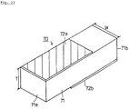
- an excitation electrode 72a and an excitation electrode 72b are formed on the top and bottom surfaces, respectively, of an elongated piezoelectric substrate 71.
- the excitation electrodes 72a and 72b extend along the whole major dimensions of the piezoelectric substrate 71, and face away from each other in the longitudinal center of the piezoelectric substrate 71 to form a resonating portion. These excitation electrodes 72a and 72b extend to longitudinal ends 71a and 71b, respectively, of the piezoelectric substrate 71.
- the energy-trapped piezoelectric resonator disclosed in Patent Unexamined Publication No. 117409/1989 and utilizing the second-order wave of a thickness extensional vibration mode needs large vibration-attenuating portions around the resonating portion. Hence, it is difficult to reduce the size of the resonator.
- the W/d of the above thickness extensional vibration mode piezoelectric satisfies any one of the following ranges:
- ratio W/d is set within any one of the five certain ranges described above, unwanted spurious vibrations due to cross-sectional edge modes and harmonics other than the used harmonic can be more effectively suppressed.
- said thickness extensional vibration mode piezoelectric resonator may be an energy-trapped piezoelectric resonator having said resonating portion and vibration-attenuating portions along only one direction, and said first and second excitation electrodes may be provided so as to extend to or close to an end of said piezoelectric plate in a direction perpendicular to said direction.
- the resonator When the resonator is constructed as described above, the resonator is built as an energy-trapped piezoelectric resonator. An amount of attenuation of vibration is exhibited in only one direction. A first and second excitation electrodes are formed so as to extend to or close to ends of the piezoelectric plate in a direction vertical to said direction. Therefore, it is not necessary to provide vibration-attenuating portions at sides of the resonating portion. Hence, miniaturization of the piezoelectric resonator can be promoted.
- said piezoelectric plate may be an elongated strip type.
- the above thickness extensional vibration mode piezoelectric resonator may further comprise a capacitor disposed on said first or second faces of said piezoelectric plate with a space therebetween, the space acting not to impede vibrations of the piezoelectric resonator.
- a piezoelectric resonator having a built-in capacitor can be offered, using a piezoelectric resonator having little unwanted spurious vibrations and good resonant characteristics.
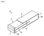
- Fig. 1 is a perspective view showing a thickness extensional piezoelectric resonator according to a first embodiment of the invention.
- Fig. 2 is a cross-sectional view of the resonator.
- the piezoelectric strip 2 is polarized uniformly in the direction of thickness as indicated by the arrows in the figure.
- a first excitation electrode 3 is formed on the top surface of the piezoelectric strip 2.
- a second excitation electrode 4 is formed on the bottom surface. Excitation electrodes 3 and 4 extend from one end 2a of the piezoelectric strip 2 to the other end 2b at the top and bottom surfaces of the piezoelectric strip 2.
- the excitation electrodes 3 and 4 are connected together by a connecting electrode 5 formed on the end surface 2a of the piezoelectric strip 2.
- An internal electrode 6 is formed at a midway level within the piezoelectric strip 2.
- the internal electrode 6 is brought out to the end surface 2b of the piezoelectric strip 2, and is electrically connected with a terminal electrode 7 formed on the end surface 2b.
- the resonator can be used as a piezoelectric resonator utilizing the second-order wave.
- the first and second excitation electrodes 3 and 4 are stacked over the internal electrode 6 via the piezoelectric layer in the longitudinal center of the piezoelectric strip 2. Therefore, in the portion where the internal electrode 6 overlaps the first and second excitation electrodes 3, 4, an energy-trapped resonating portion is formed. When this resonating portion is resonating, the energy is attenuated by the piezoelectric portions extending from the resonating portion to the end surfaces 2a and 2b.
- vibration-attenuating portions are formed at longitudinally opposite sides only in the longitudinal direction (first direction) of the piezoelectric strip 2.
- the first and second excitation electrodes extend to the ends of the piezoelectric strip in a direction perpendicular to the longitudinal direction, i.e., to the longitudinal ends.
- the first and second excitation electrodes 3, 4 and the internal electrode 6 are only required to extend along the whole width of the piezoelectric strip 2 only in the resonating portion 6. Outside the resonating portion, this width is not always required to be maintained. Take the excitation electrode 3 as an example. The excitation electrode 3 only needs to extend along the whole width of the piezoelectric strip 2 only in the resonating portion. The portion of the excitation electrode on the side of the end surface 2a may be thinner, because it simply electrically connects the excitation electrode with the connecting electrode 5.
- the thickness extensional piezoelectric resonator 1 can effectively suppress unwanted spurious vibrations due to lateral-mode vibrations, as will be described by referring to Figs. 24 and 3-11.
- Fig. 23 shows strong resonance due to cross-sectional edge mode of the piezoelectric substrate 71.
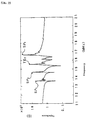
- Fig. 24 shows the impedance-frequency characteristic of this piezoelectric resonator 70.
- a vibration mode indicated by the arrow TE 2 is the second-order wave of a thickness extensional vibration mode.
- Responses indicated by SE 1 -SE 3 are spurious vibrations due to the cross-sectional edge mode.
- the impedance-frequency characteristic shown in Fig. 24 is derived from the piezoelectric resonator 70 having a resonance frequency of 16 MHz.
- spurious vibrations indicated by SP 1 , SP 2 , and SP 3 appear near 13.5, 14.5, and 16.5 MHz, respectively. It is observed that every spurious vibration is considerably large.
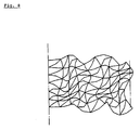
- Figs. 4-8 are horizontal cross sections of a thickness extensional piezoelectric resonator 1 in a strip form as shown in Fig. 3, schematically showing, on an enlarged scale, the displacements of a surface of a half of the strip-type piezoelectric resonator 1 when taken in a direction perpendicular to the longitudinal direction and in the direction of thickness.
- Figs. 4-8 are modes of displacements of cross-sectional edge modes and referred to as SE 0 -SE 4 , respectively. It is considered that the SP 1 , SP 2 , and SP 3 are either based on cross-sectional edge mode spurious vibration SE 2 or accompany it.
- the frequency constant referred to herein is the antiresonant frequency fa multiplied by d to make the frequency a constant.
- the ratio W/d As can be seen from Fig. 12, where the ratio W/d is changed, the relative bandwidth varies. Especially, where the W/d is in excess of 6, resonant points of vibrations due to cross-sectional edge modes (indicated by X in Fig. 12) appear in the passband. Where the ratio W/d is less than 6.1, a thickness extensional piezoelectric resonator insusceptible to vibrations due to cross-sectional edge modes can be derived by appropriately selecting the value of the ratio W/d. Especially, where the ratio W/d is set within the ranges of Eqs. (1)-(5), the resonance of cross-sectional edge mode indicated by X does not lie within the passband between the resonant point (O) and antiresonant point ( ⁇ ) and so good resonant characteristics can be obtained.
- the ratio W/d of the piezoelectric plate 2 is set less than 6.1 as mentioned above. Therefore, where a piezoelectric resonator utilizing the second-order wave TE 2 of a thickness extensional vibration mode is constructed, unwanted spurious vibrations due to cross-sectional edge modes can be effectively suppressed. In consequence, good resonant characteristics can be had.
- the piezoelectric strip 2 is polarized uniformly in the direction of thickness.
- the piezoelectric resonator is connected in a parallel configuration such that the applied electric field is reversed with each of the successive layers.
- the invention may also be applied to a series-connection type piezoelectric resonator in which plural piezoelectric layers are polarized alternately oppositely in the direction of thickness.
- a thickness extensional piezoelectric resonator of such a series type is shown in Fig. 13.
- a thickness extensional piezoelectric resonator, 11, shown in Fig. 13 is made of an elongated rectangular piezoelectric strip 12.
- a first excitation electrode 13 is formed on the top surface of the piezoelectric strip 12.
- a second excitation electrode 14 is formed on the bottom surface.
- the first and second excitation electrodes 13 and 14, respectively, are located on opposite side of the piezoelectric strip 12.
- the first and second excitation electrodes 13 and 14 are opposite to each other in the longitudinal center of the piezoelectric strip 12.
- the portion where the first and second excitation electrodes 13 and 14 are opposite to each other makes an energy-trapped resonating portion.
- the first and second excitation electrodes 13 and 14 are brought out to end surfaces 12a and 12b, respectively, of the piezoelectric strip 12.
- the portions other than the resonating portion are not required to extend along the whole length of the piezoelectric strip 12.
- the excitation electrodes 13 and 14 form an energy-trapped resonating portion having vibration-attenuating portions in the longitudinal direction of the piezoelectric strip 12.
- the first and second excitation electrodes 13 and 14 extend to the longitudinal ends of the piezoelectric strip 12 in a direction vertical to the longitudinal direction.
- An internal electrode 16 is formed at a midway height within the piezoelectric strip 12, and acts to polarize the piezoelectric strip 12. That is, during polarization, piezoelectric layers 12c and 12d are polarized in opposite directions in the direction of thickness as indicated by the arrows by applying a higher voltage and a lower voltage to the internal electrode 16 and the excitation electrodes 13, 14, respectively.
- an AC voltage is applied between the first and second excitation electrodes 13 and 14, respectively. That is, the internal electrode 16 is not used for the operation.
- the second-order wave TE 2 of a thickness extensional vibration mode can be excited.
- the thickness extensional vibration mode piezoelectric resonator 11 according to the second embodiment can effectively suppress unwanted spurious vibrations due to cross-sectional edge modes, since the ratio W/d is set within any one of the five ranges described above. As a result, good resonant characteristics can be obtained.
- the first and second embodiments provide piezoelectric resonators 1 and 11 both utilizing the second-order wave of a thickness extensional vibration mode.
- Piezoelectric resonators in accordance with the present invention may make use of harmonics other than the second-order wave of a thickness extensional vibration mode.
- Figs. 14-17 are cross-sectional views illustrating piezoelectric resonators utilizing these harmonics, and correspond to Fig. 2 used to describe the first embodiment.
- Fig. 14 is a parallel-connection type thickness extensional piezoelectric resonator, 21, utilizing the third-order wave of a thickness extensional vibration mode.
- two internal electrodes 22 and 23 are disposed in a piezoelectric body 2.
- the piezoelectric body 2 is polarized uniformly in the direction of thickness as indicated by the arrow.
- the piezoelectric resonator 21 exploiting the third-order wave of a thickness extensional vibration mode can be built.
- a thickness extensional piezoelectric resonator, 24, shown in Fig. 15 is a cross-sectional view showing a parallel-connection type piezoelectric resonator 24 utilizing the fourth-order wave of a thickness extensional vibration mode.
- the piezoelectric strip 2 is polarized uniformly in the direction of thickness.
- Three internal electrodes 25-27 are regularly spaced from each other in the direction of thickness inside the resonator. Consequently, the fourth-order wave of a thickness extensional vibration mode is effectively excited.
- Fig. 16 is a cross-sectional view showing a series-connection type thickness extensional piezoelectric resonator, 28, utilizing the third-order wave of a thickness extensional vibration mode.
- this thickness extensional piezoelectric resonator 28 two internal electrodes 29 and 30 are disposed in a piezoelectric body 12.
- the inside of the piezoelectric body 12 is divided into three layers of piezoelectric layers 12e-12g. Polarization is performed, using these internal electrodes 29 and 30, so that piezoelectric layers adjacent to each other in the direction of thickness are polarized in opposite directions.
- the third-order wave of a thickness extensional vibration mode can be excited by applying an AC voltage to the first and second excitation electrodes 13 and 14.
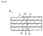
- Fig. 17 is a cross-sectional view showing a series-connection type piezoelectric resonator, 31, utilizing the fourth-order wave of a thickness extensional vibration mode.
- three internal electrodes 32-34 are disposed in a piezoelectric body 12. Polarization is carried out, using these internal electrodes 32-34, such that piezoelectric layers adjacent to each other in the direction of thickness are polarized in opposite directions.
- the ratio W/d is set within any one of the five ranges described above. Therefore, harmonics of a thickness extensional vibration can be exploited, in the same way as the first and second embodiments. Furthermore, unwanted spurious vibrations due to responses of cross-sectional edge modes or other harmonics can be effectively suppressed.
- Fig. 18 is a perspective view for illustrating a thickness extensional piezoelectric resonator according to a third embodiment of the invention.
- Fig. 19 is a diagram showing its equivalent circuit.
- Fig. 18 shows a piezoelectric resonator 41 that is a combination of the thickness extensional piezoelectric resonator 1 according to the first embodiment and a capacitor 42. This capacitor 42 is bonded to the bottom surface of the thickness extensional piezoelectric resonator 1 via conductive adhesive 43, 44.
- capacitive electrodes 42b and 42c are formed via a given gap on the top surface of a dielectric substrate 42a.
- a common electrode 42d is formed on the bottom surface of the dielectric substrate 42a.
- the common electrode 42d and the capacitive electrodes 42b, 42c are located on opposite sides of the dielectric substrate 42a.
- the conductive adhesive 43 bonds the capacitive electrode 42b to a terminal electrode 7.
- the conductive adhesive 44 bonds the capacitive electrode 42c to a terminal electrode 5.
- the piezoelectric resonator 41 can be used as a piezoelectric resonator incorporating two capacitive units.
- the thickness extensional piezoelectric resonator 1 is a piezoelectric resonator utilizing the second-order waves of thickness extensional vibrations. Spurious vibrations attributed to cross-sectional edge modes can be effectively suppressed. Therefore, piezoelectric resonators having good frequency characteristics can be offered.
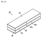
- Fig. 20 is a perspective view showing a further modified example of the thickness extensional piezoelectric resonator in accordance with the present invention.
- a thickness extensional piezoelectric resonator in accordance with the present invention is characterized in that the resonator makes use of harmonics of a thickness extensional vibration mode and that the ratio W/d is set within the five certain ranges described above. Thus, unwanted spurious vibrations due to cross-sectional edge modes and other harmonics are suppressed. That is, the invention is not limited to an energy-trapped piezoelectric resonator. As shown in Fig. 20, the invention can also be applied to a thickness extensional piezoelectric resonator other than the energy-trapped type.
- a thickness extensional piezoelectric resonator 45 comprises an elongated, rectangular piezoelectric strip 46.
- the ratio W/d of this piezoelectric strip 46 is set within any one of the five certain ranges described in connection with the first embodiment.
- a first excitation electrode 47 and a second excitation electrode 48 are formed over the whole top surface and over the whole bottom surface, respectively, of the piezoelectric strip 46.
- An internal electrode 50 is disposed inside the piezoelectric strip. In this piezoelectric strip 46, adjacent piezoelectric layers 46a and 46b are polarized oppositely in the direction of thickness.
- the W/d is set within the certain ranges described above. Unwanted spurious vibrations due to cross-sectional edge modes and other harmonics can be effectively suppressed, in the same way as in the thickness extensional piezoelectric resonator 11 according to the second embodiment. Good resonant characteristics can be obtained.
Landscapes
- Physics & Mathematics (AREA)
- Acoustics & Sound (AREA)
- Piezo-Electric Or Mechanical Vibrators, Or Delay Or Filter Circuits (AREA)
Applications Claiming Priority (3)
| Application Number | Priority Date | Filing Date | Title |
|---|---|---|---|
| JP9155281A JPH114133A (ja) | 1997-06-12 | 1997-06-12 | 厚み縦圧電共振子 |
| JP15528197 | 1997-06-12 | ||
| JP155281/97 | 1997-06-12 |
Publications (2)
| Publication Number | Publication Date |
|---|---|
| EP0884840A2 true EP0884840A2 (fr) | 1998-12-16 |
| EP0884840A3 EP0884840A3 (fr) | 2000-03-22 |
Family
ID=15602479
Family Applications (1)
| Application Number | Title | Priority Date | Filing Date |
|---|---|---|---|
| EP98109649A Withdrawn EP0884840A3 (fr) | 1997-06-12 | 1998-05-27 | Résonateur piézoélectrique résonnant en mode d'extension d'épaisseur |
Country Status (4)
| Country | Link |
|---|---|
| US (1) | US6107727A (fr) |
| EP (1) | EP0884840A3 (fr) |
| JP (1) | JPH114133A (fr) |
| CN (1) | CN1114989C (fr) |
Cited By (2)
| Publication number | Priority date | Publication date | Assignee | Title |
|---|---|---|---|---|
| US6700302B1 (en) | 1999-07-23 | 2004-03-02 | Murata Manufacturing Co., Ltd. | Piezoelectric resonator |
| EP1077092A3 (fr) * | 1999-08-16 | 2004-03-17 | Murata Manufacturing Co., Ltd. | Elément piezoélectrique |
Families Citing this family (11)
| Publication number | Priority date | Publication date | Assignee | Title |
|---|---|---|---|---|
| US4817048A (en) * | 1986-08-11 | 1989-03-28 | Amdahl Corporation | Divider with quotient digit prediction |
| JP3461453B2 (ja) * | 1998-12-16 | 2003-10-27 | 株式会社村田製作所 | 厚み縦圧電共振子及び圧電共振部品 |
| JP2000183683A (ja) * | 1998-12-17 | 2000-06-30 | Murata Mfg Co Ltd | 厚み縦圧電共振子及び圧電共振部品 |
| JP3324536B2 (ja) * | 1998-12-18 | 2002-09-17 | 株式会社村田製作所 | 厚み縦圧電共振子及び圧電共振部品 |
| JP3334669B2 (ja) * | 1999-03-29 | 2002-10-15 | 株式会社村田製作所 | 圧電共振部品 |
| JP2001068961A (ja) | 1999-08-26 | 2001-03-16 | Murata Mfg Co Ltd | 厚み縦圧電共振子、ラダー型フィルタ及び圧電共振部品 |
| US7164221B1 (en) * | 1999-10-01 | 2007-01-16 | Ngk Insulators, Ltd. | Piezoelectric/electrostrictive device and method of manufacturing same |
| US6915547B2 (en) * | 1999-10-01 | 2005-07-12 | Ngk Insulators, Ltd. | Piezoelectric/electrostrictive device and method of manufacturing same |
| JP4015820B2 (ja) * | 2001-04-11 | 2007-11-28 | 日本碍子株式会社 | 配線基板及びその製造方法 |
| AU2004238868B2 (en) * | 2003-05-12 | 2010-01-21 | Affymax, Inc. | Peptides that bind to the erythropoietin receptor |
| CN114636410B (zh) * | 2022-02-25 | 2024-05-10 | 中国科学院西安光学精密机械研究所 | 一种变壁厚伞形半球谐振子及半球谐振陀螺 |
Citations (3)
| Publication number | Priority date | Publication date | Assignee | Title |
|---|---|---|---|---|
| JPS59115609A (ja) * | 1982-12-22 | 1984-07-04 | Murata Mfg Co Ltd | 圧電フイルタ |
| US5045744A (en) * | 1988-12-23 | 1991-09-03 | Murata Mfg. Co. | Energy-trapping-by-frequency-lowering-type piezoelectric-resonance device |
| JPH08242026A (ja) * | 1995-03-03 | 1996-09-17 | Fujitsu Ltd | 圧電振動子及びこれを具備する圧電振動子デバイス並びに該デバイスを具備する回路装置 |
Family Cites Families (7)
| Publication number | Priority date | Publication date | Assignee | Title |
|---|---|---|---|---|
| JPS6194408A (ja) * | 1984-10-15 | 1986-05-13 | Nec Corp | セラミツクフイルタ |
| JP2790178B2 (ja) * | 1987-06-26 | 1998-08-27 | 株式会社村田製作所 | 電歪共振装置 |
| JPS6412711A (en) * | 1987-07-07 | 1989-01-17 | Murata Manufacturing Co | Chip type resonator |
| JPH01288005A (ja) * | 1988-05-13 | 1989-11-20 | Fujitsu Ltd | 圧電振動素子 |
| JPH02235422A (ja) * | 1989-03-08 | 1990-09-18 | Matsushita Electric Ind Co Ltd | 厚み縦共振子 |
| JPH0559955U (ja) * | 1992-01-09 | 1993-08-06 | 株式会社村田製作所 | 圧電共振器 |
| JPH06125242A (ja) * | 1992-10-13 | 1994-05-06 | Fujitsu Ltd | 圧電振動子 |
-
1997
- 1997-06-12 JP JP9155281A patent/JPH114133A/ja active Pending
-
1998
- 1998-05-27 EP EP98109649A patent/EP0884840A3/fr not_active Withdrawn
- 1998-06-03 US US09/089,820 patent/US6107727A/en not_active Expired - Lifetime
- 1998-06-12 CN CN98109887A patent/CN1114989C/zh not_active Expired - Lifetime
Patent Citations (4)
| Publication number | Priority date | Publication date | Assignee | Title |
|---|---|---|---|---|
| JPS59115609A (ja) * | 1982-12-22 | 1984-07-04 | Murata Mfg Co Ltd | 圧電フイルタ |
| US5045744A (en) * | 1988-12-23 | 1991-09-03 | Murata Mfg. Co. | Energy-trapping-by-frequency-lowering-type piezoelectric-resonance device |
| JPH08242026A (ja) * | 1995-03-03 | 1996-09-17 | Fujitsu Ltd | 圧電振動子及びこれを具備する圧電振動子デバイス並びに該デバイスを具備する回路装置 |
| US5925968A (en) * | 1995-03-03 | 1999-07-20 | Fujitsu Limited | Piezoelectric vibrator, piezoelectric vibrator device having the same and circuit device having the piezoelectric vibrator device |
Cited By (2)
| Publication number | Priority date | Publication date | Assignee | Title |
|---|---|---|---|---|
| US6700302B1 (en) | 1999-07-23 | 2004-03-02 | Murata Manufacturing Co., Ltd. | Piezoelectric resonator |
| EP1077092A3 (fr) * | 1999-08-16 | 2004-03-17 | Murata Manufacturing Co., Ltd. | Elément piezoélectrique |
Also Published As
| Publication number | Publication date |
|---|---|
| EP0884840A3 (fr) | 2000-03-22 |
| US6107727A (en) | 2000-08-22 |
| CN1211857A (zh) | 1999-03-24 |
| CN1114989C (zh) | 2003-07-16 |
| JPH114133A (ja) | 1999-01-06 |
Similar Documents
| Publication | Publication Date | Title |
|---|---|---|
| US6107727A (en) | Thickness extensional vibration mode piezoelectric resonator | |
| EP0884842B1 (fr) | Résonateur piézoélectrique à piégeage d'énergie en mode d'extension d'épaisseur | |
| US6362561B1 (en) | Piezoelectric vibration device and piezoelectric resonance component | |
| JP3324536B2 (ja) | 厚み縦圧電共振子及び圧電共振部品 | |
| US6198200B1 (en) | Thickness extensional vibration piezoelectric resonator and piezoelectric resonance apparatus | |
| US6051910A (en) | Thickness extensional vibration mode piezoelectric resonator and piezoelectric resonator component | |
| EP0884841B1 (fr) | Résonateur piézoélectrique à piégeage d'énergie en mode d'extension d'épaisseur | |
| JP3461453B2 (ja) | 厚み縦圧電共振子及び圧電共振部品 | |
| US6967432B2 (en) | Piezoelectric shear resonator, composite piezoelectric shear resonator, and piezoelectric resonator component | |
| JP3485115B2 (ja) | エネルギー閉じ込め型厚み縦圧電共振子 | |
| JP3139274B2 (ja) | 幅拡がりモードを利用した振動体、共振子及び共振部品 | |
| JP3485114B2 (ja) | 厚み縦圧電共振子及び圧電共振部品 | |
| JP3271541B2 (ja) | 圧電共振子およびそれを用いた電子部品 | |
| JP3473613B2 (ja) | 厚み縦圧電共振子及び圧電共振部品 | |
| JP3322170B2 (ja) | エネルギー閉じ込め型厚み縦圧電共振子 | |
| JP3271538B2 (ja) | 圧電共振子およびそれを用いた電子部品 | |
| JPH1127083A (ja) | 厚み縦圧電共振子及び圧電共振部品 | |
| JP3509813B2 (ja) | エネルギー閉じ込め型厚み縦圧電共振子 | |
| JPH118527A (ja) | 厚み縦圧電共振子 | |
| JPH118529A (ja) | エネルギー閉じ込め型厚み縦圧電共振子 | |
| JP2000183684A (ja) | 厚み縦圧電共振子及び圧電共振部品 | |
| JPH114136A (ja) | 厚み縦圧電共振子 | |
| JP2002368570A (ja) | 厚み縦圧電共振子 |
Legal Events
| Date | Code | Title | Description |
|---|---|---|---|
| PUAI | Public reference made under article 153(3) epc to a published international application that has entered the european phase |
Free format text: ORIGINAL CODE: 0009012 |
|
| 17P | Request for examination filed |
Effective date: 19980527 |
|
| AK | Designated contracting states |
Kind code of ref document: A2 Designated state(s): DE NL |
|
| AX | Request for extension of the european patent |
Free format text: AL;LT;LV;MK;RO;SI |
|
| PUAL | Search report despatched |
Free format text: ORIGINAL CODE: 0009013 |
|
| AK | Designated contracting states |
Kind code of ref document: A3 Designated state(s): AT BE CH CY DE DK ES FI FR GB GR IE IT LI LU MC NL PT SE |
|
| AX | Request for extension of the european patent |
Free format text: AL;LT;LV;MK;RO;SI |
|
| AKX | Designation fees paid |
Free format text: DE NL |
|
| RAP1 | Party data changed (applicant data changed or rights of an application transferred) |
Owner name: MURATA MANUFACTURING CO., LTD. |
|
| 17Q | First examination report despatched |
Effective date: 20070926 |
|
| STAA | Information on the status of an ep patent application or granted ep patent |
Free format text: STATUS: THE APPLICATION IS DEEMED TO BE WITHDRAWN |
|
| 18D | Application deemed to be withdrawn |
Effective date: 20080408 |